Download as PDF, PPTX


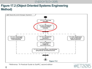
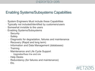
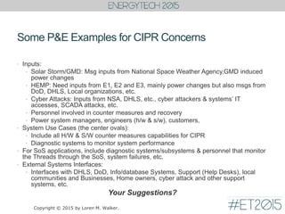
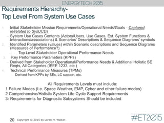
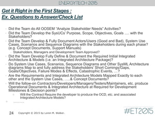
![Example System UC Diagram (top level)
‘Support Executive Manager with Financial Information’
14
Key Users &
Orgs (Good
& Bad)
Ext. System
Functions,
Tools, etc.
System Use Cases, Goals, etc.
(Key Functions/Activities)
System
Boundary
Human
Machine
I/F (HMI)
System to
System
I/Fs
Establishes System Boundaries & Operational & Enabling Elements
with Descriptions (i.e. Key Driving Requirements/Topics)
Enabling Sys
Use Cases
with Actors
Copyright © 2015 by Loren M. Walker.
uc [Package] Getting Started [ExampleFinancialSUCD]
ToBe Financial System Boundary
Provide Executive
Financial Support
Senior Exec
Analysts
Managers
Trainers
Info & DB
Managers
Provide Info & DB
Capabilities
Provide Performance
Capabilities
Provide Training
Capabilities
«actor»
External Financial
System
«actor»
Backup Storage
System
«actor»
Performance
Tools
Trainees
0..*
1..*
1..*
1..*
1
1..*
1..*
1..*
1..*
1..*
1..*
0..1
1..*](https://image.slidesharecdn.com/tues-151209025503-lva1-app6891/85/Mark-Walker-Model-Based-Systems-Engineering-Initial-Stages-for-Power-AMP-Energy-14-320.jpg)
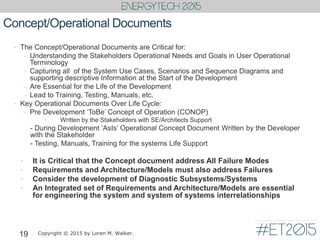
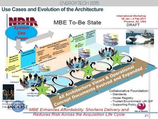

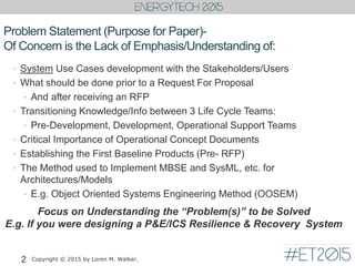
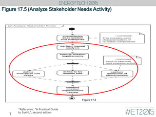
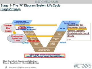
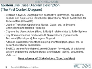
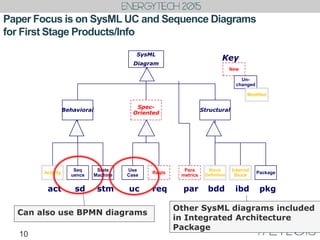
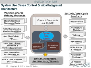
The document emphasizes the critical importance of early stages in system development, particularly in the context of object-oriented systems engineering and model-based systems engineering. It discusses the necessity of understanding stakeholder needs, developing system use cases, and the importance of operational concept documents for ensuring that systems meet operational goals and expectations. Key topics include the integration of various life cycle teams and the establishment of foundational architecture and requirements to address potential failure modes and support comprehensive development processes.