1. The document discusses electromagnetic induction and various concepts related to electricity including magnetic fields, electric current, induction, and circuits.
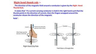
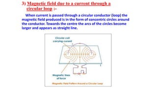
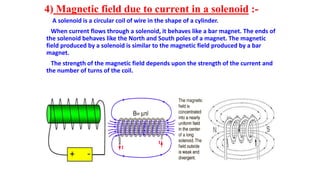
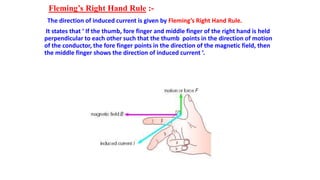
2. It explains how magnetic fields are produced by magnets and electric currents, and how changing magnetic fields can induce electric currents based on Fleming's rules.
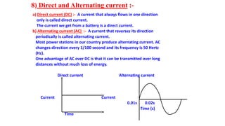
3. Key aspects of domestic electric circuits are outlined, including how homes receive alternating current which is then distributed to circuits protected by fuses from overloading and short circuits.