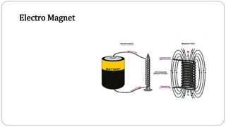
1. An electromagnet works by aligning the atoms in a magnetic material like iron through an electric current, creating a strong magnetic field. The stronger the current, the stronger the magnetic field, up to the point of saturation where all atoms are aligned.
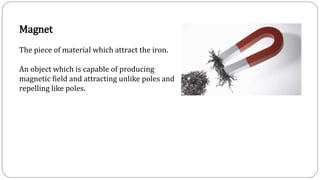
2. Magnets have properties like attracting ferromagnetic materials, opposite poles attracting and like poles repelling, and aligning north to south when free to move. Magnetic field lines form closed loops and never intersect.
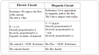
3. In a magnetic circuit, magnetic flux is produced by current in a wire and measured in Webers. Magnetomotive force (MMF) drives flux and is measured in Ampere-turns. Permeability indicates a material