Download as PDF, PPTX
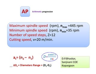
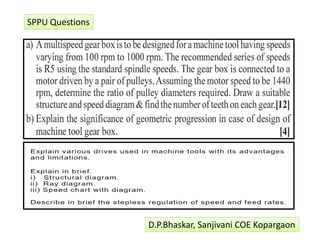
![Why Multi‐Speeds ?
24/01/2017 3
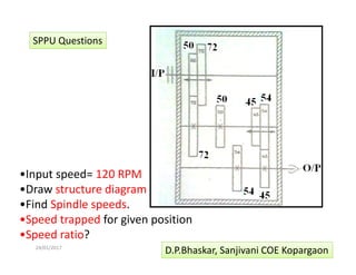
Different :
• Feeds
• W/P Materials
• W/P Dimensions [D]
• Cutting tool materials
n1
n2
n3
n4
n5
n6
n7
n8
N9= nz
nem
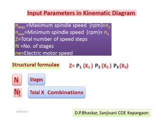
D.P.Bhaskar, Sanjivani COE Kopargaon
1
1](https://image.slidesharecdn.com/msgb16-17students-170124115843/85/MACHINE-TOOL-GEAR-BOX-3-320.jpg)
![24/01/2017 30
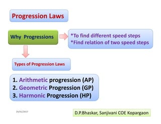
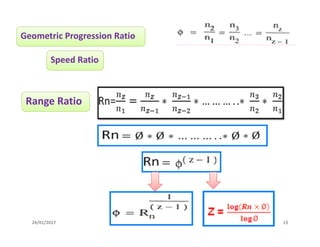
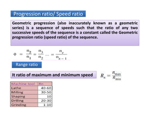
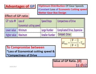
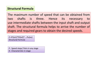
In gearbox design a set of preferred step ratio or preferred
numbers is used to obtain the series of output speed of
gearbox. The preferred step ratio is mentioned as basic series
named as R5, R10,R20,R40 and R80. Each basic series has a
specific step ratio. R [Charles Renard]
Definition of preferred number/speed series](https://image.slidesharecdn.com/msgb16-17students-170124115843/85/MACHINE-TOOL-GEAR-BOX-30-320.jpg)
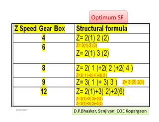

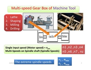
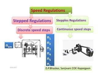
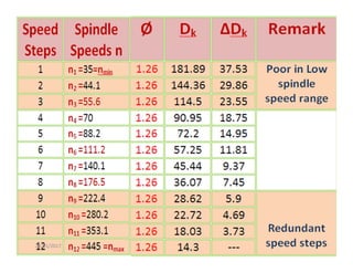
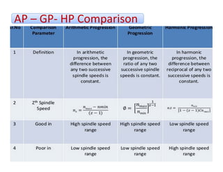
The document discusses multi-speed gearboxes used in machine tools. It explains that gearboxes provide multiple spindle speeds from a single motor speed to accommodate different feeds, workpiece materials and dimensions, and cutting tool materials. It then describes arithmetic, geometric and harmonic progressions used to calculate speed steps and ensures optimal distribution of speeds. Various terms related to gearbox design such as structural formula, ray diagram, speed chart and gearing diagram are also defined.