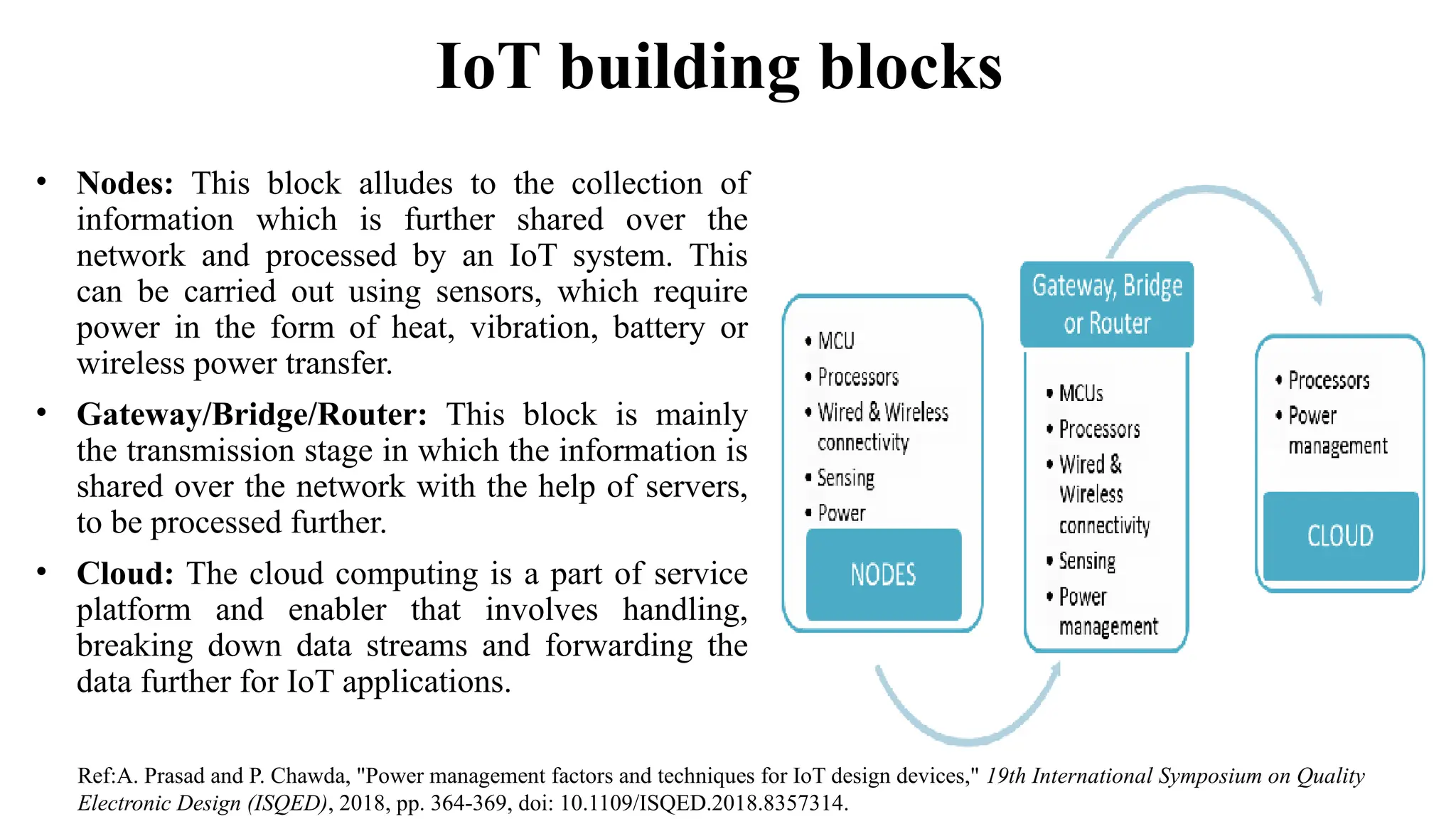
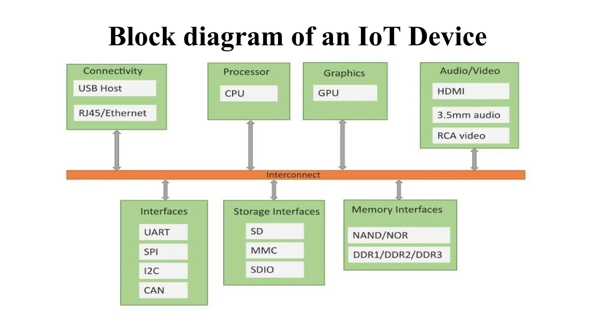
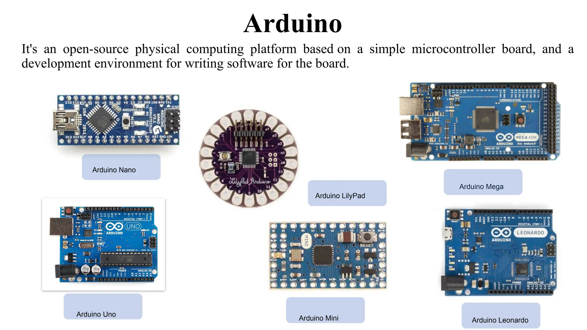
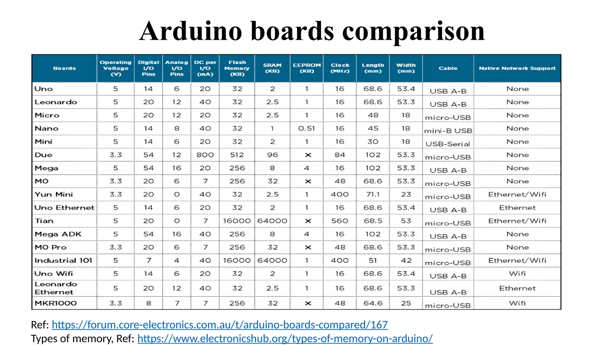
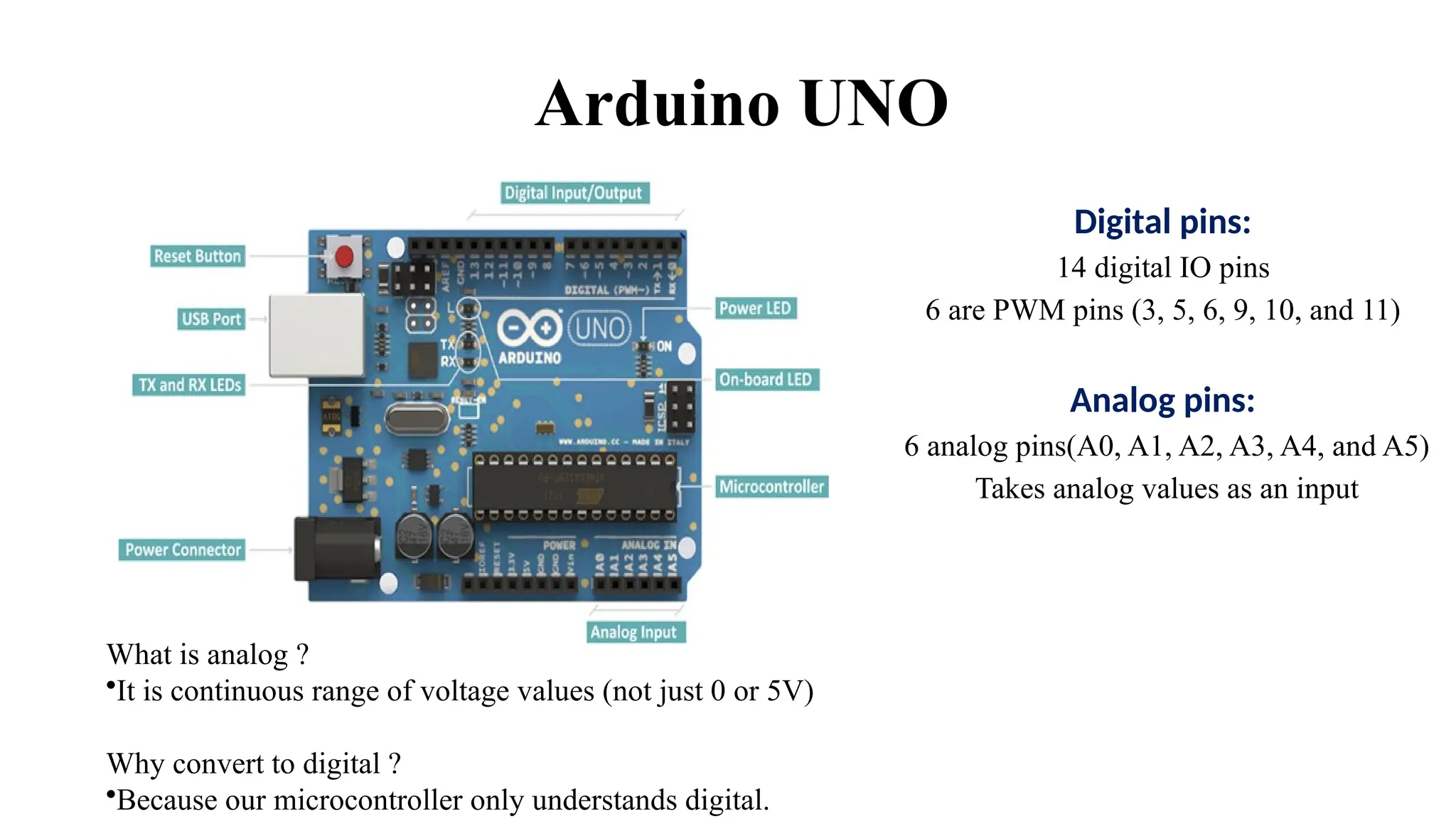
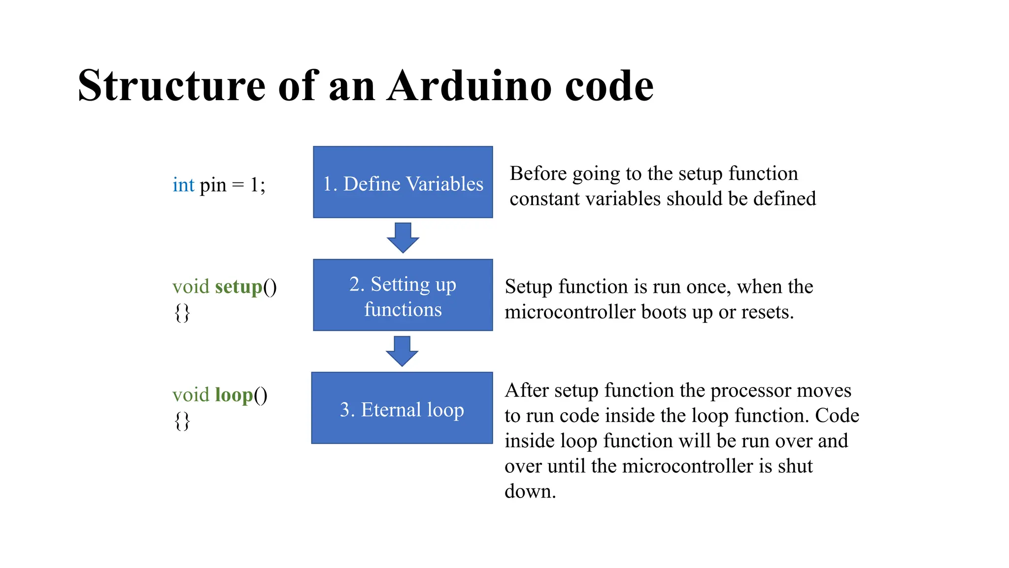
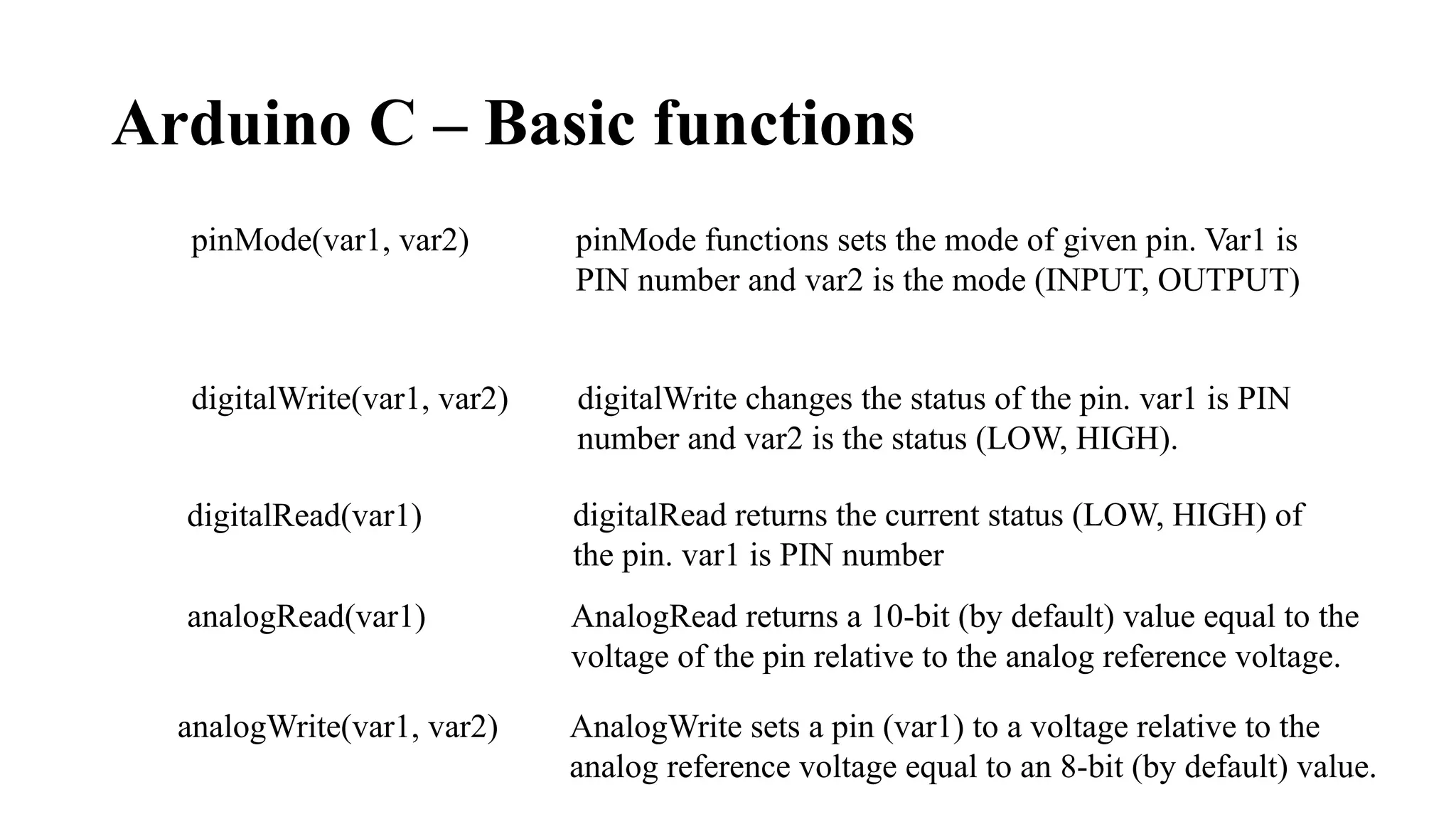
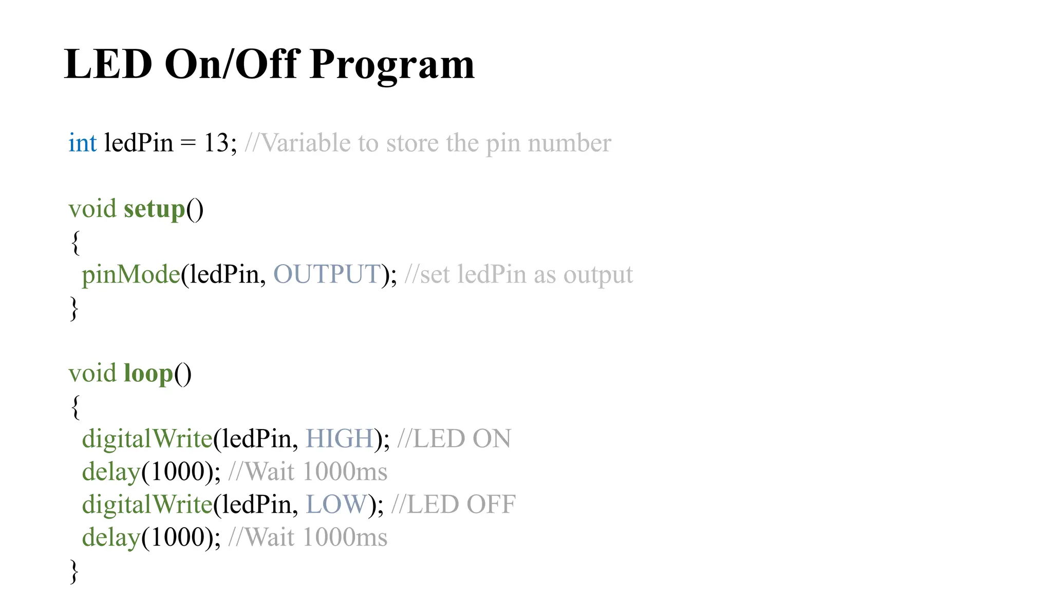
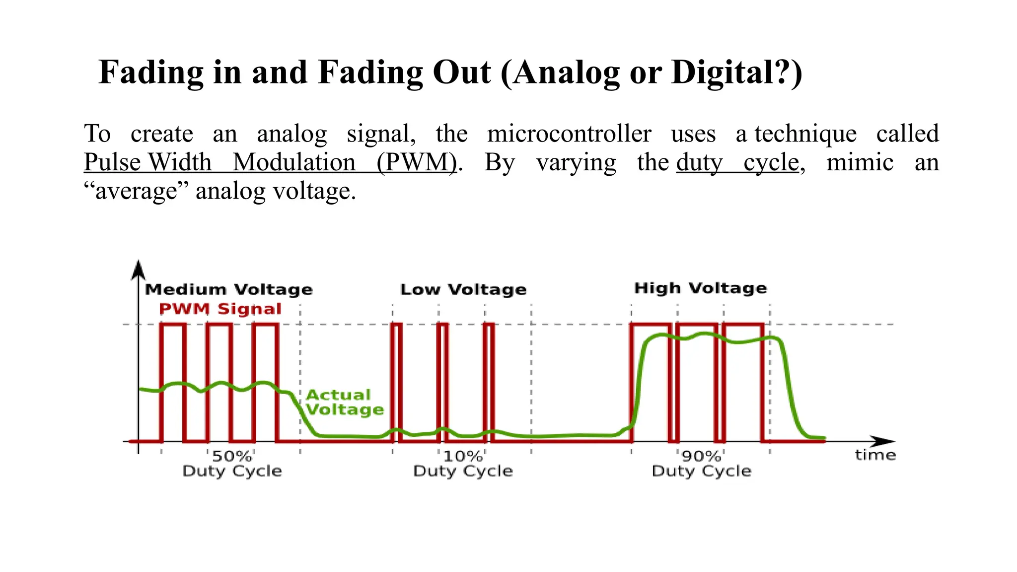
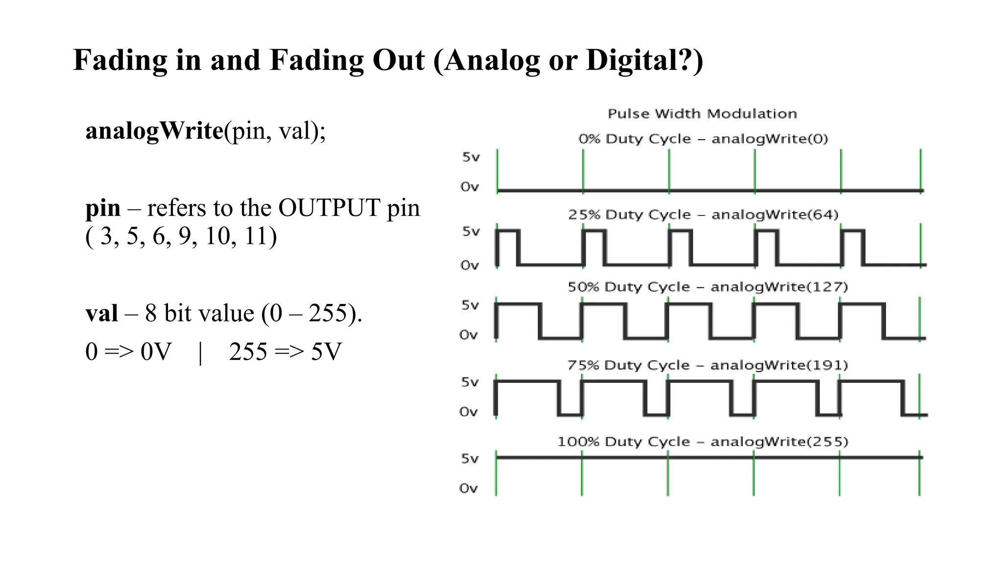
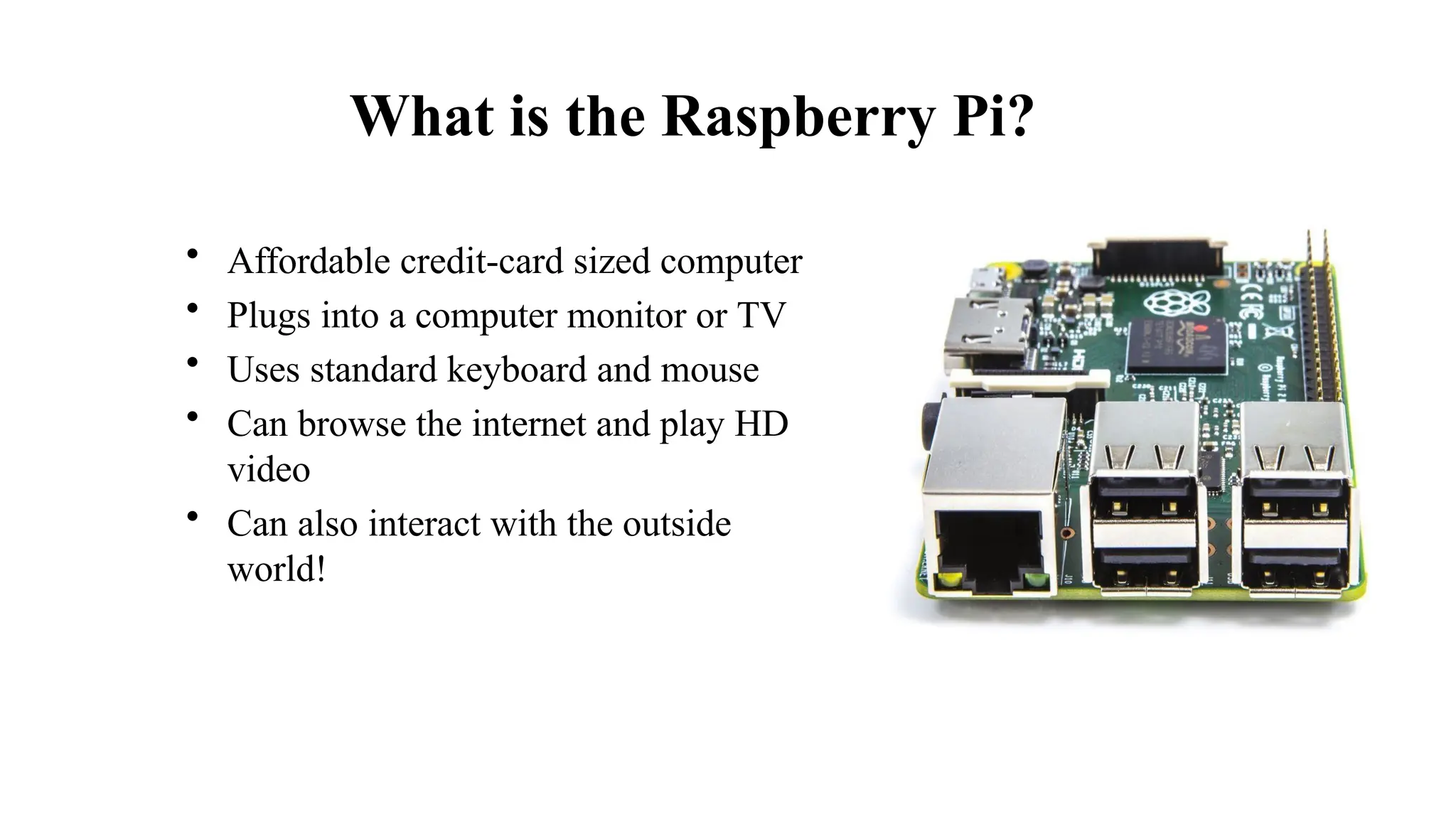
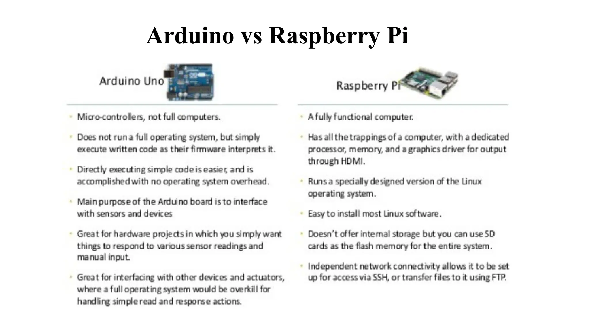
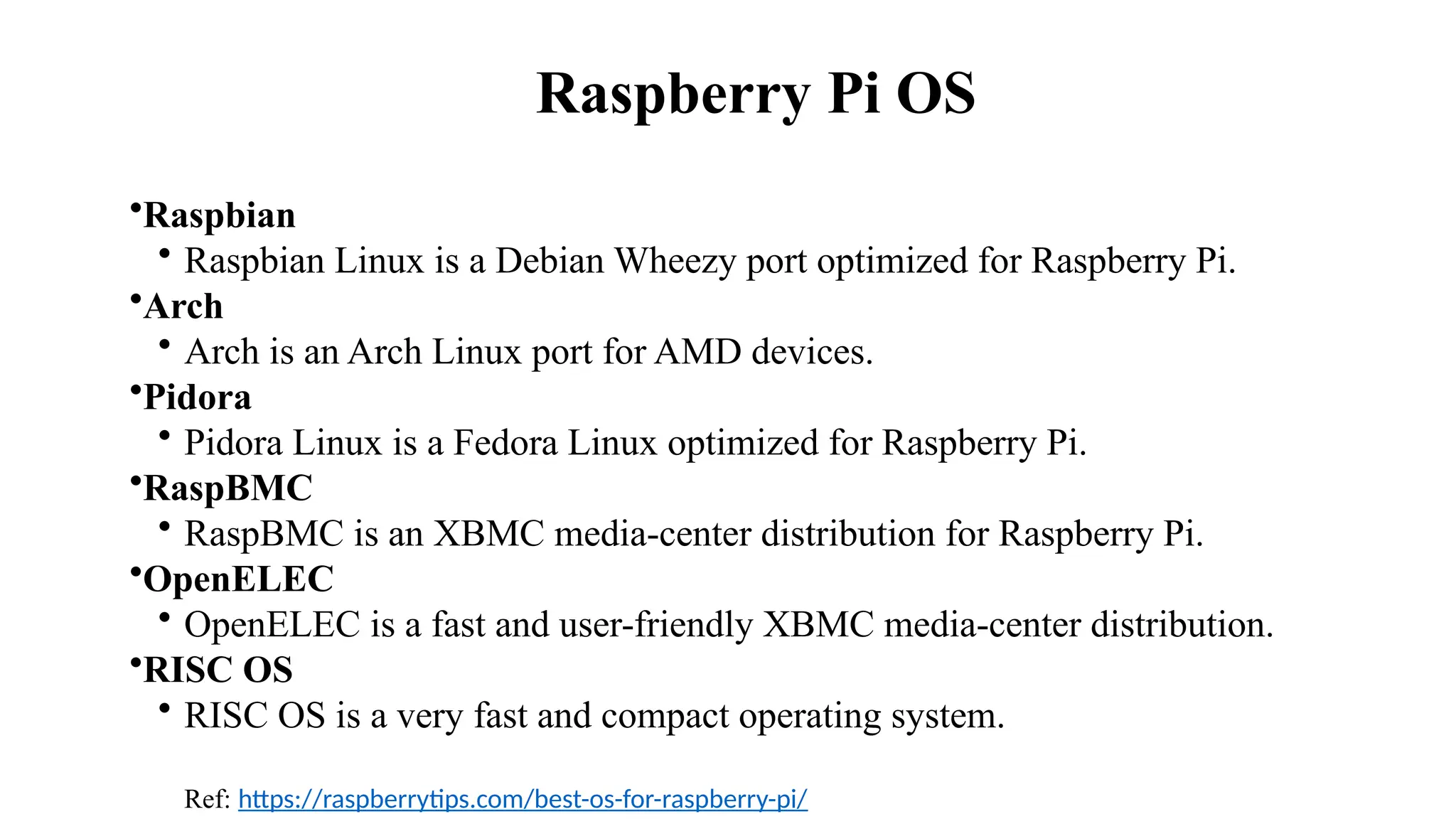
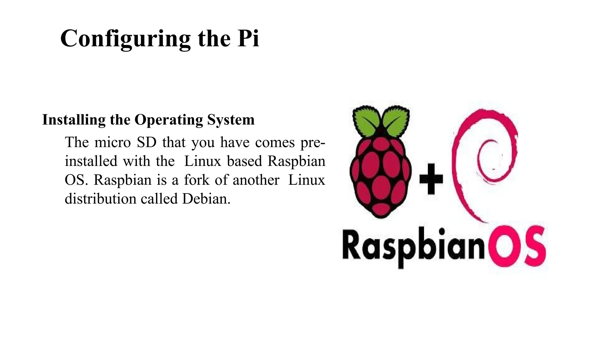
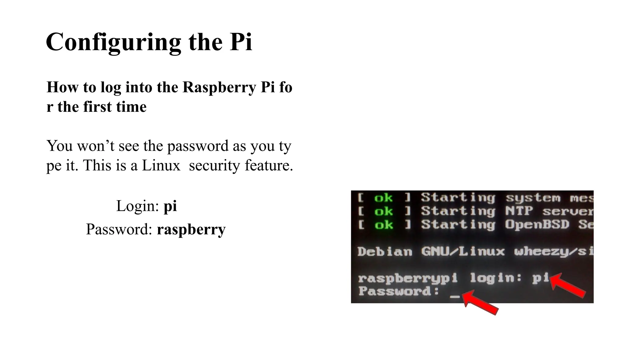
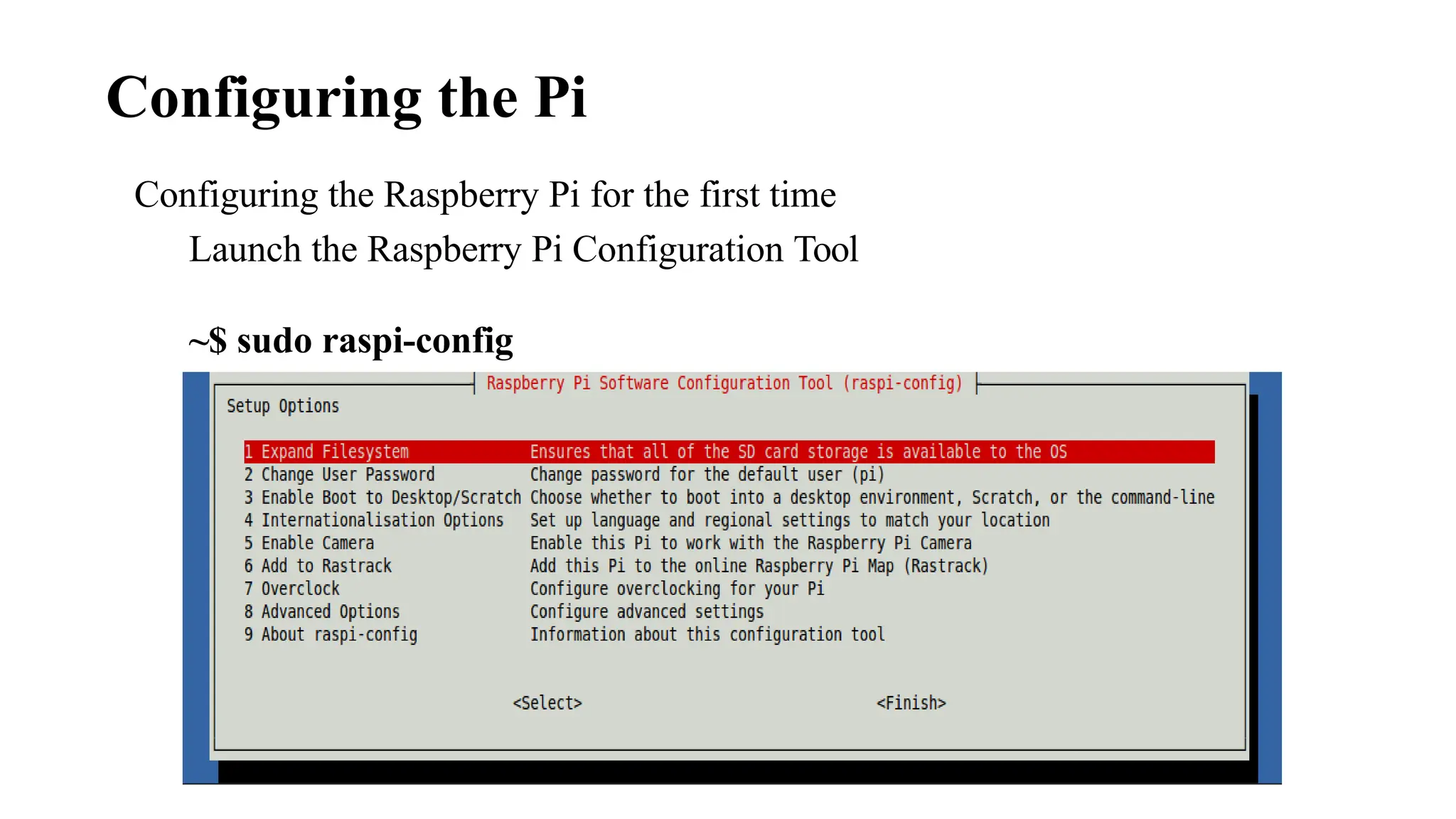
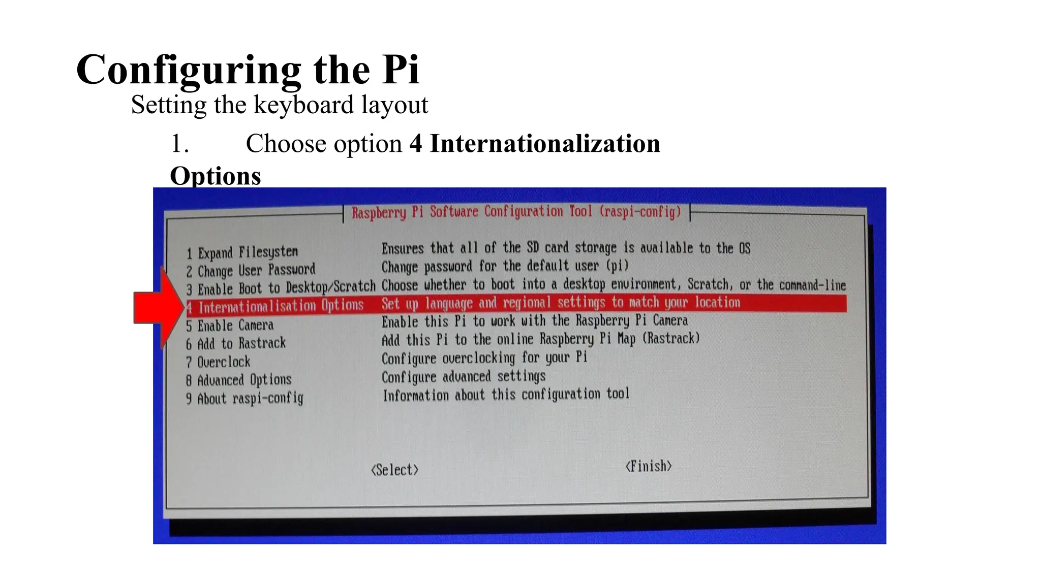
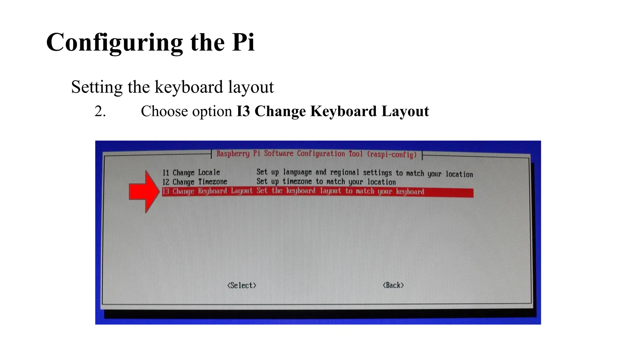
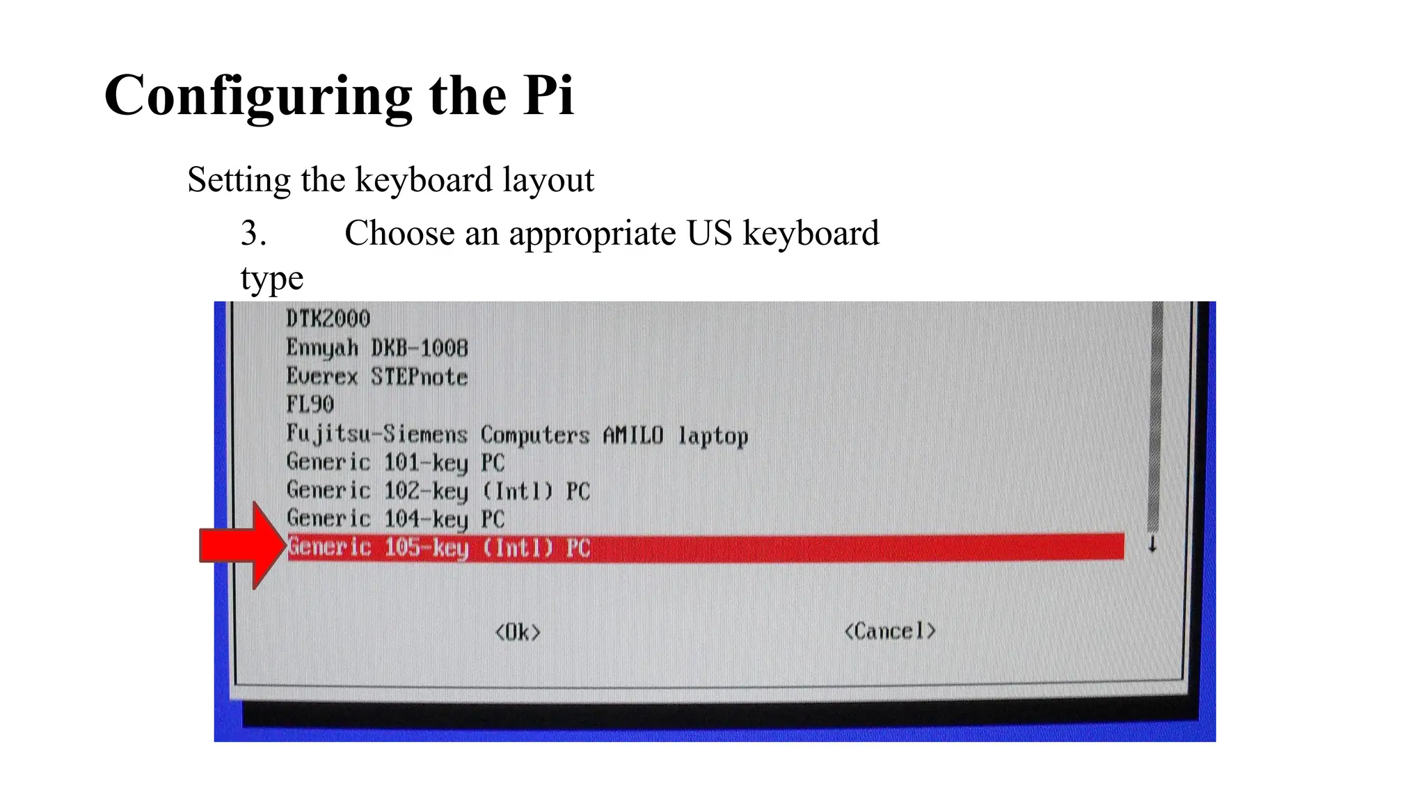
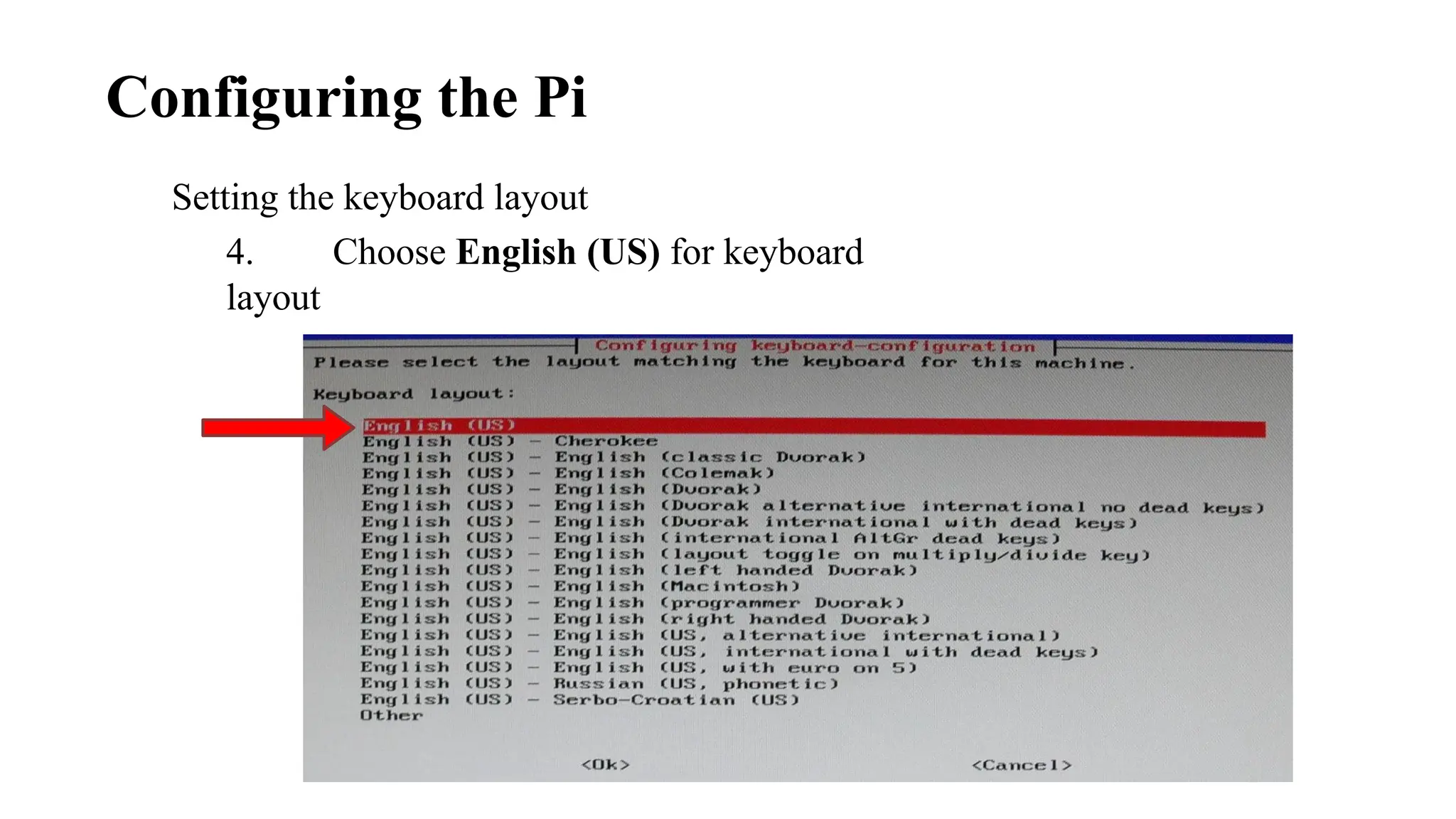
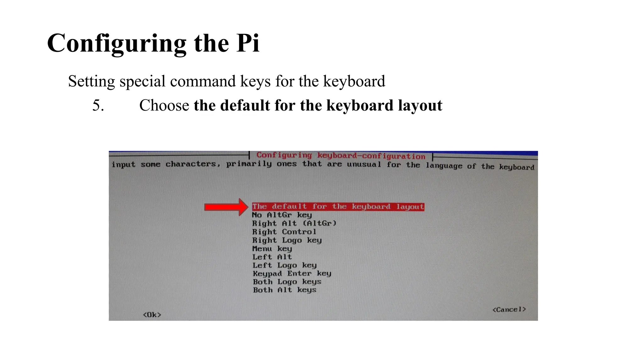
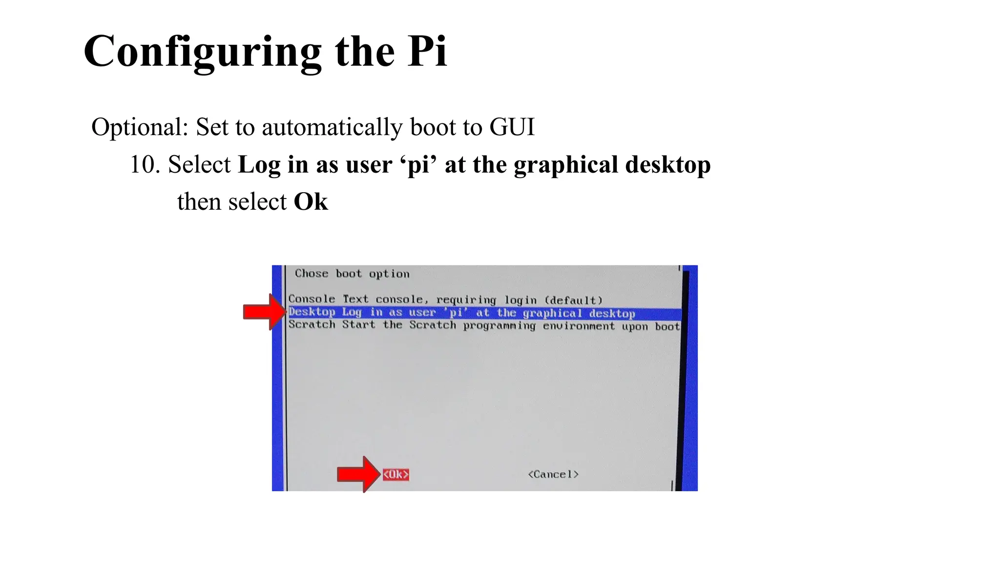
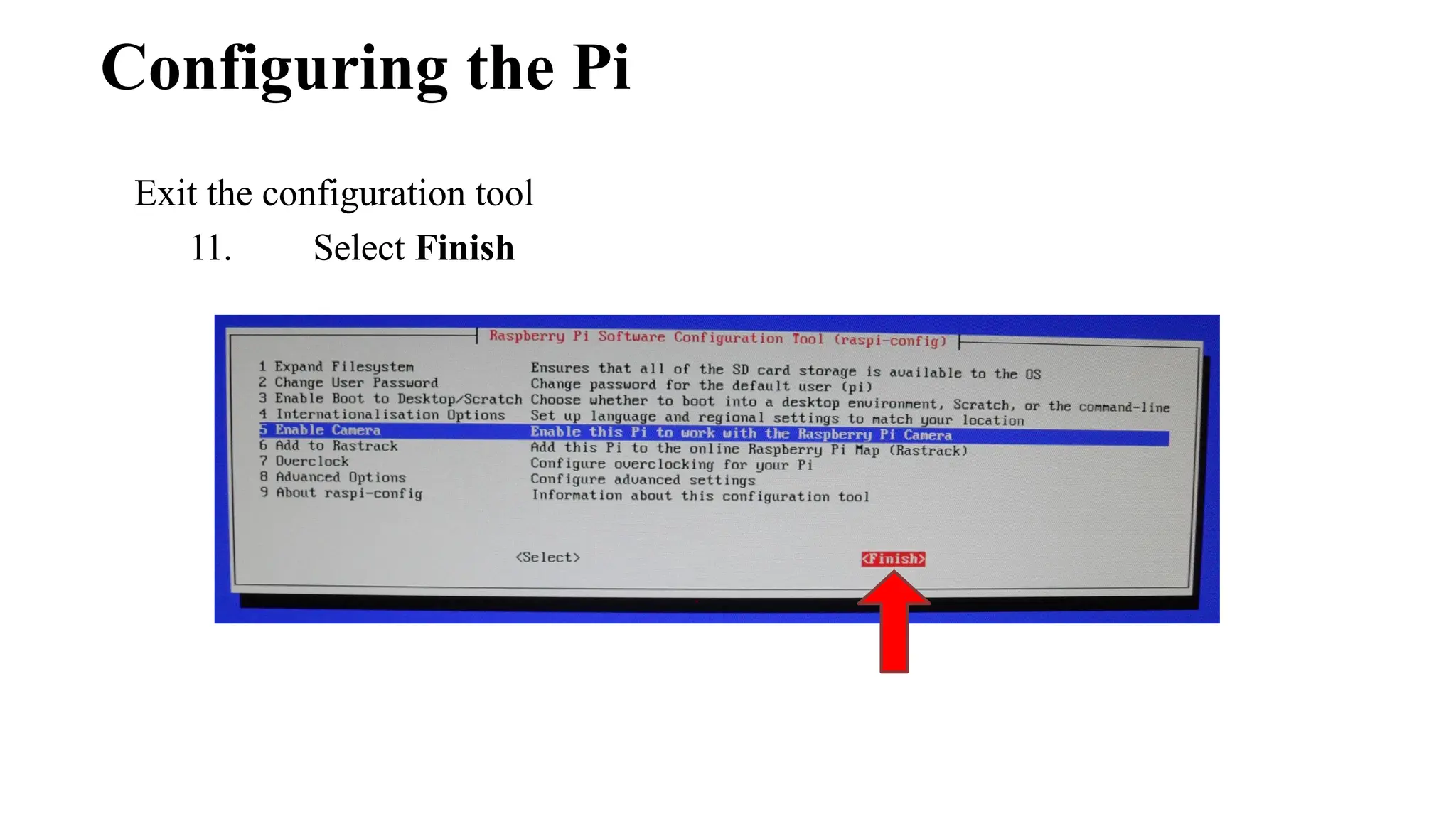
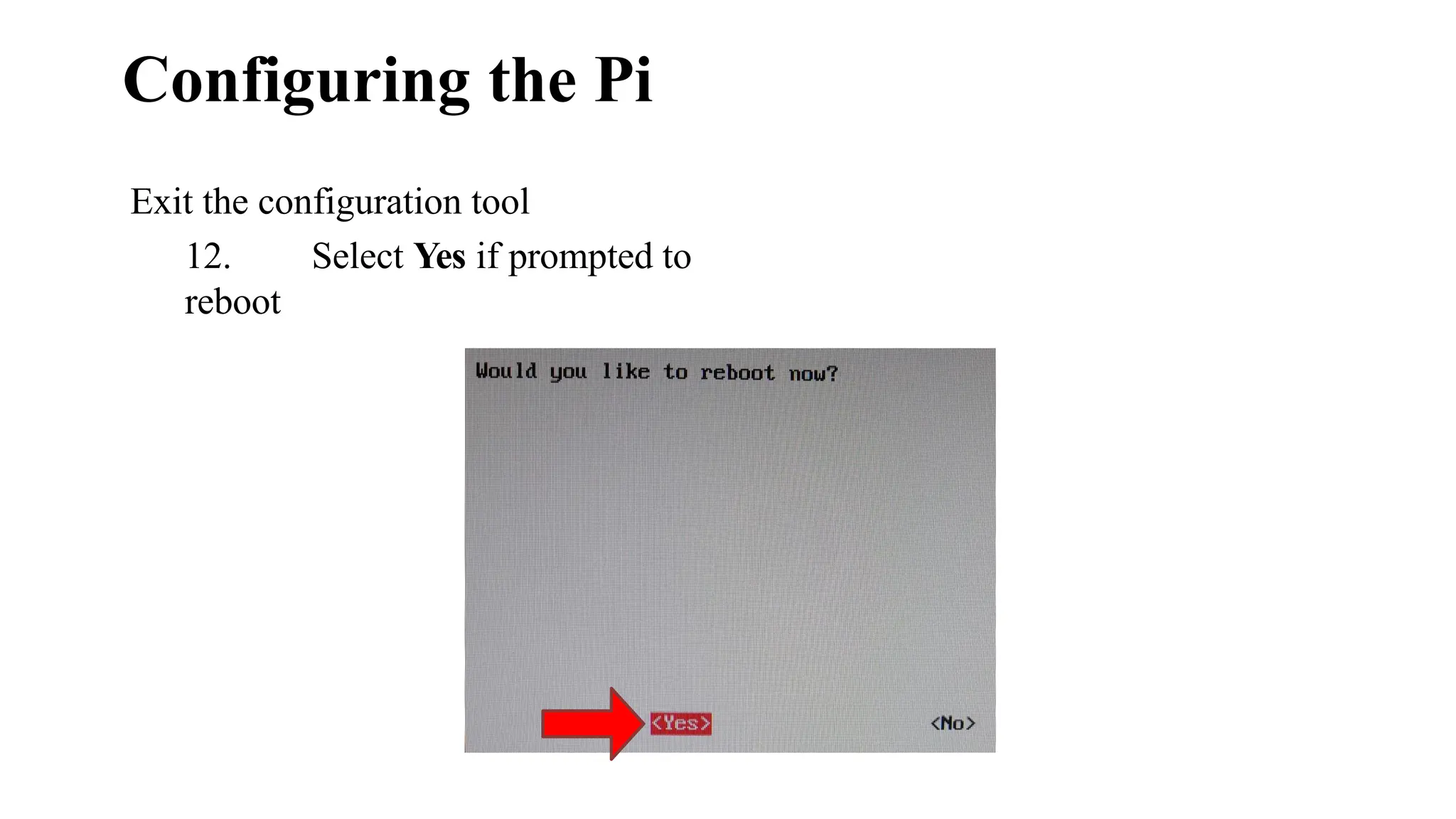
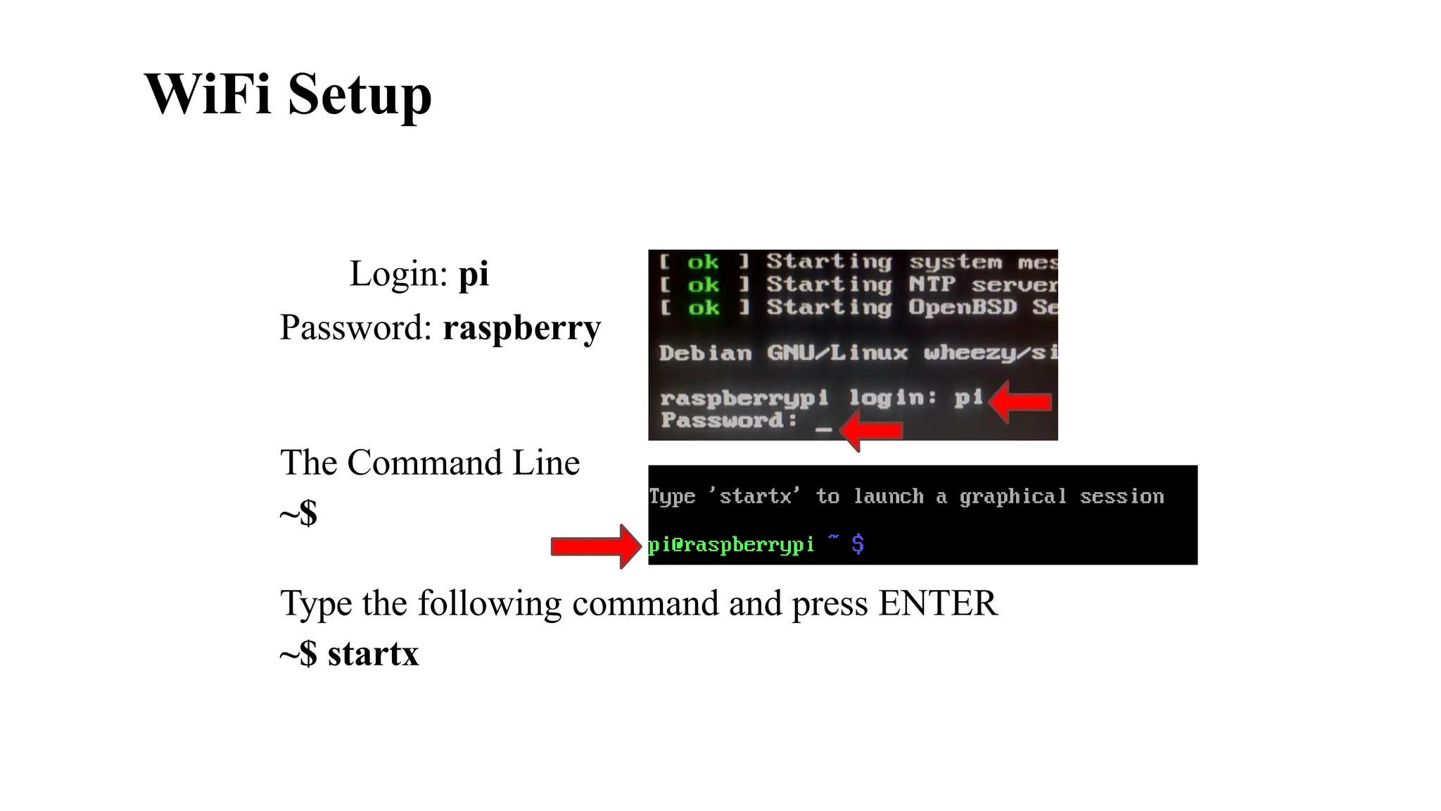
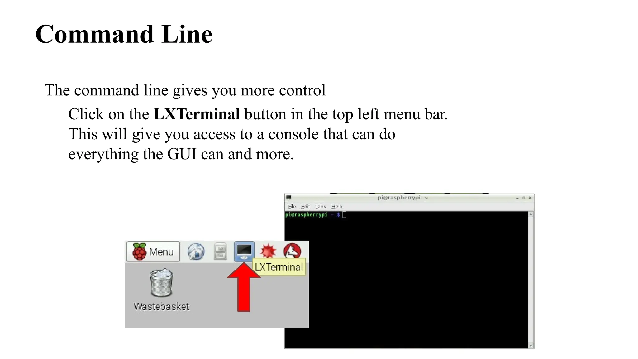
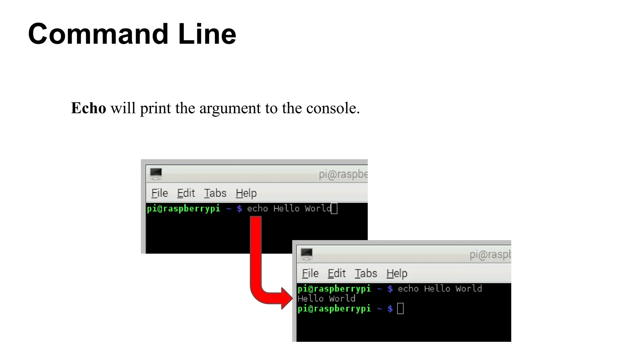
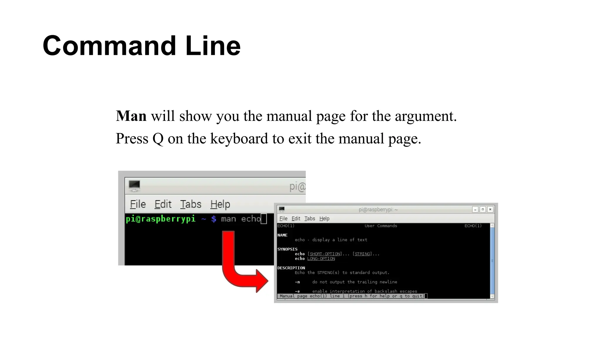
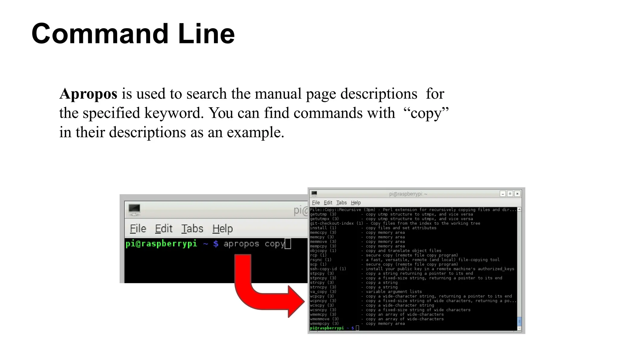
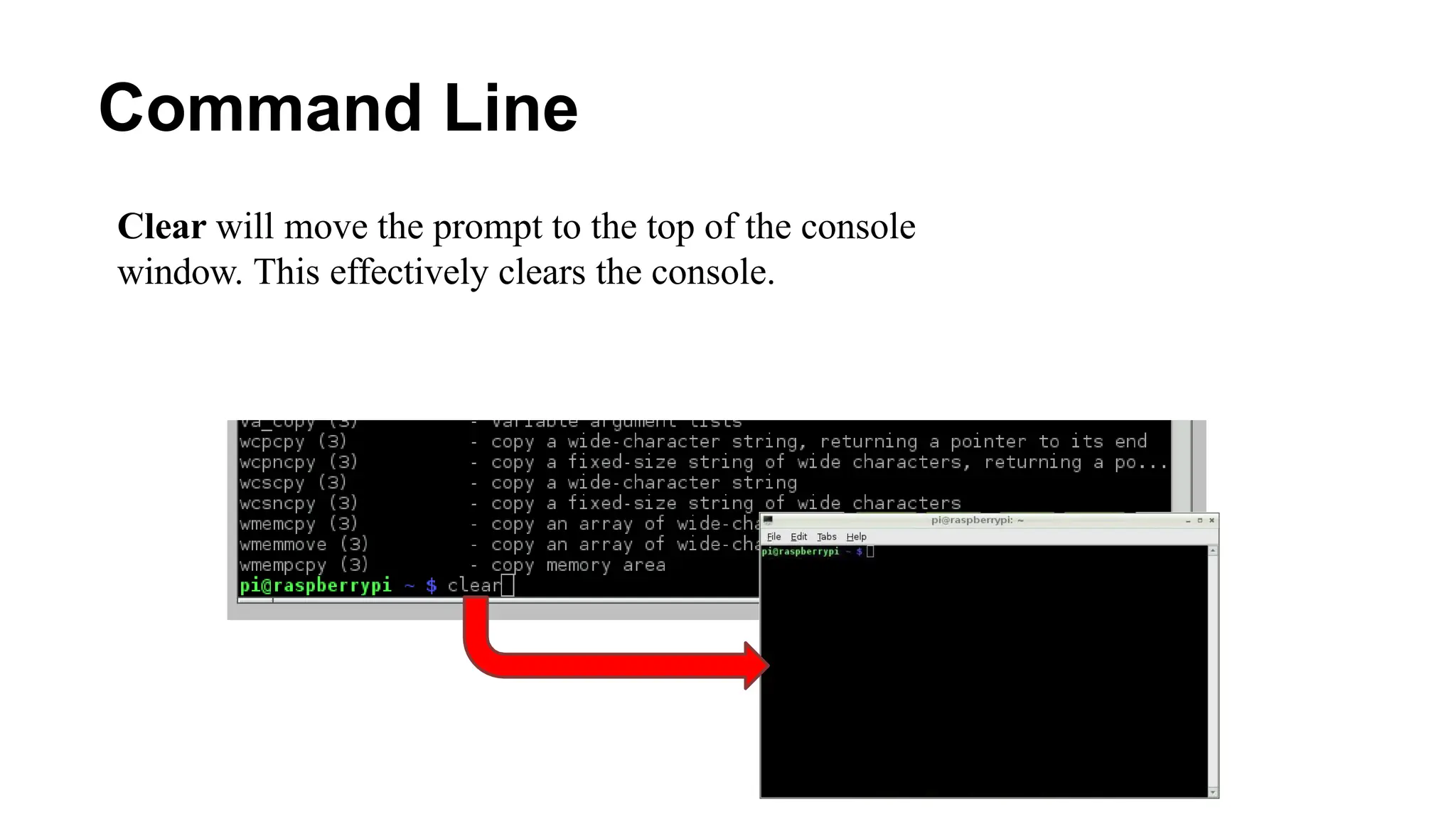
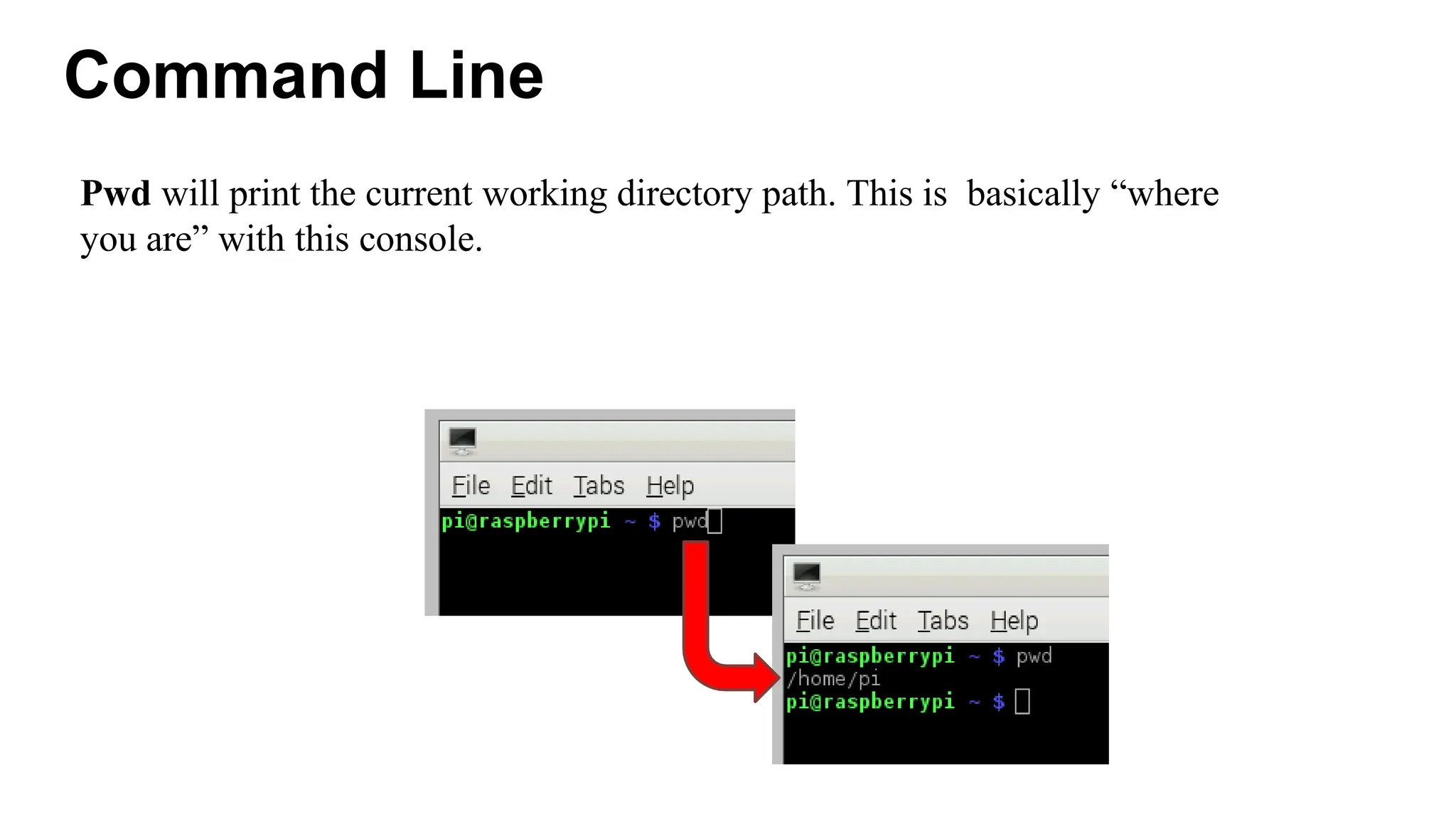
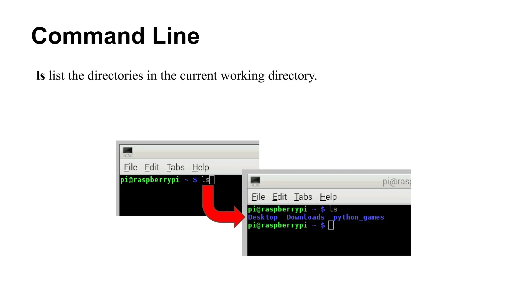
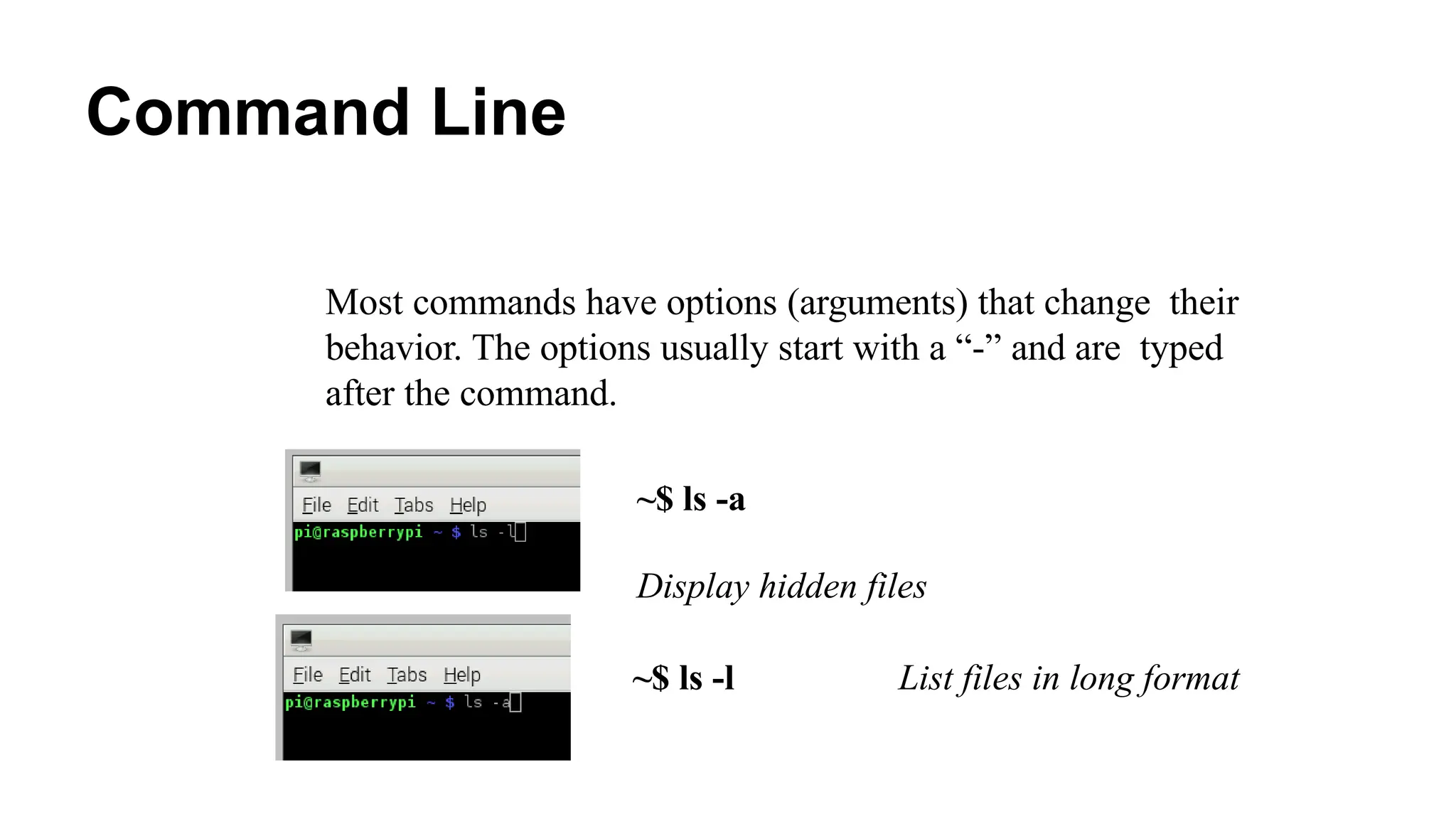
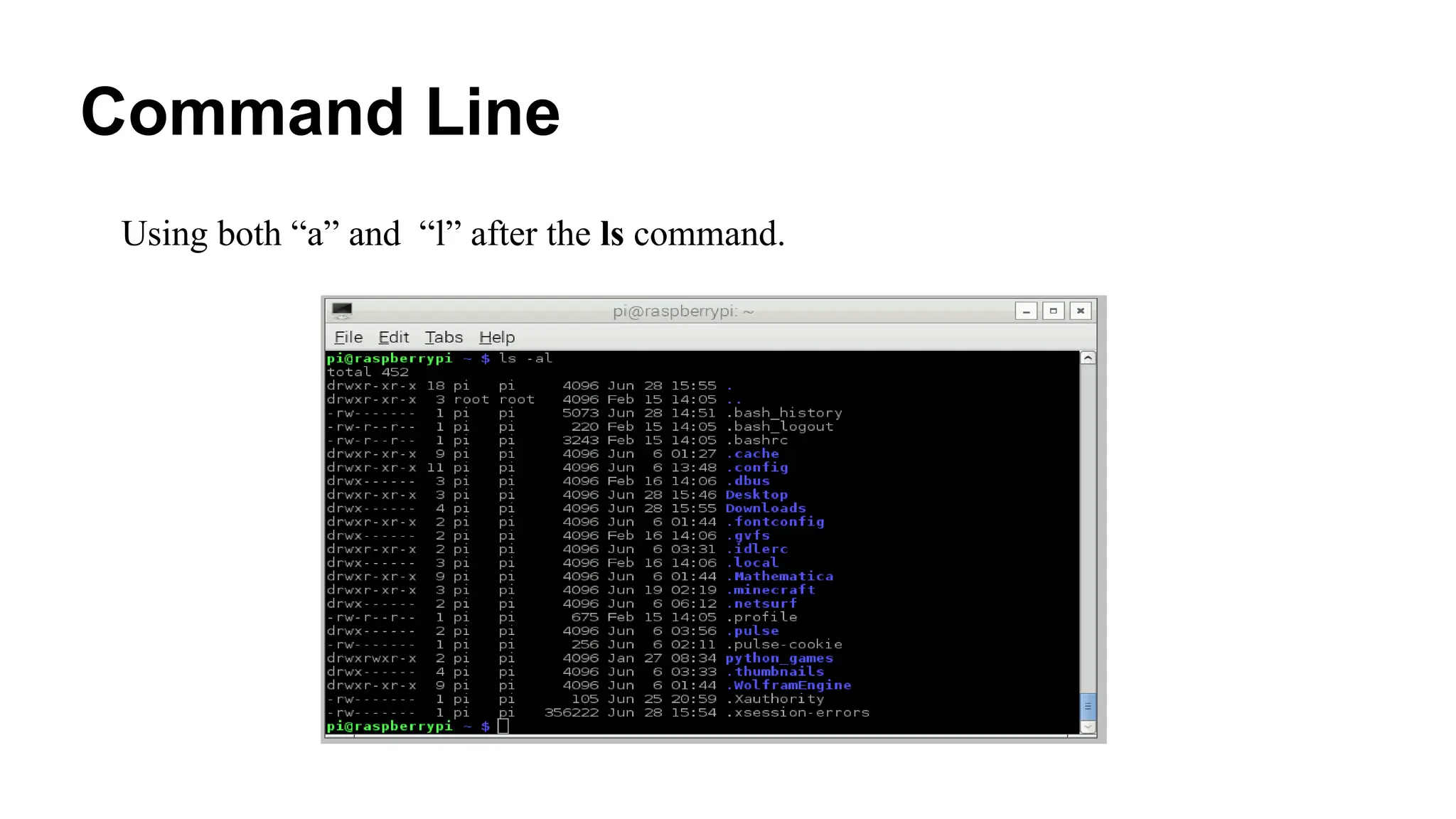
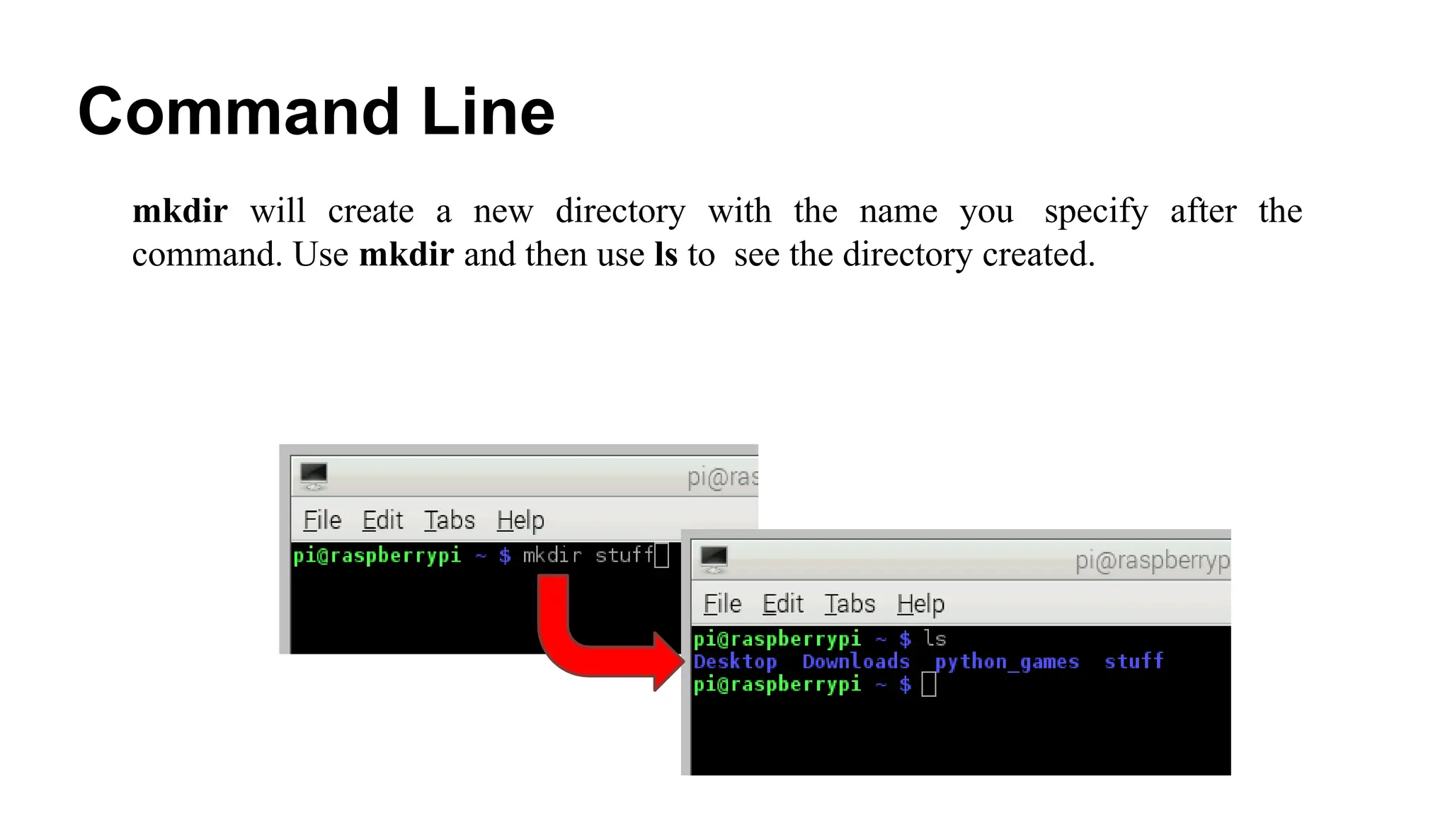
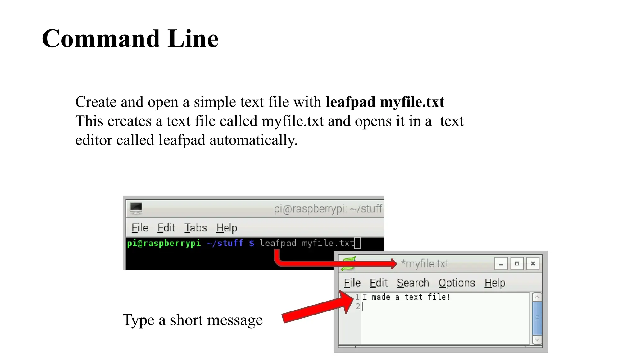
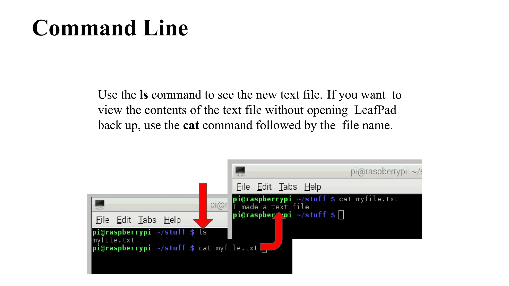
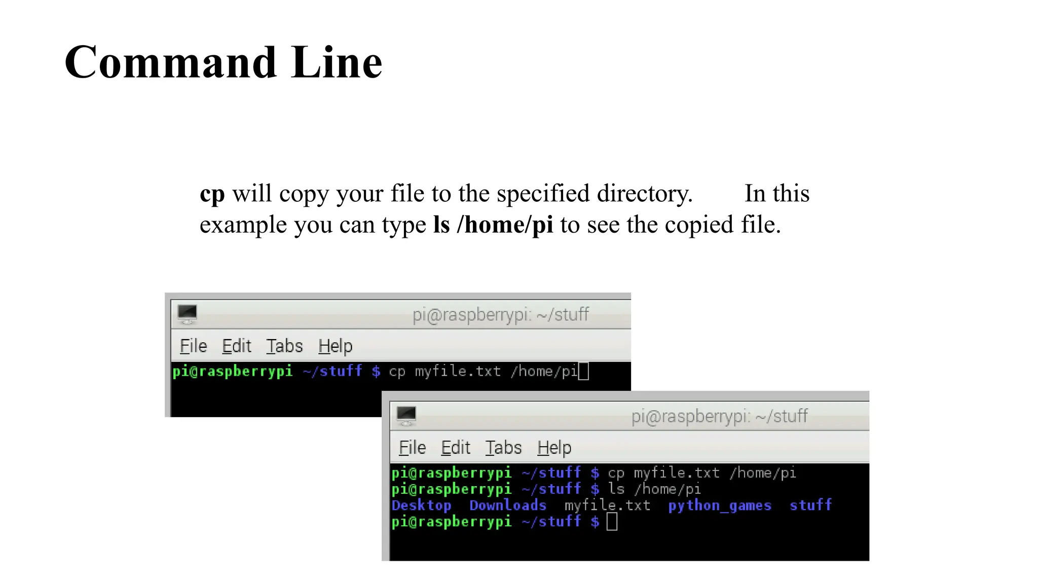
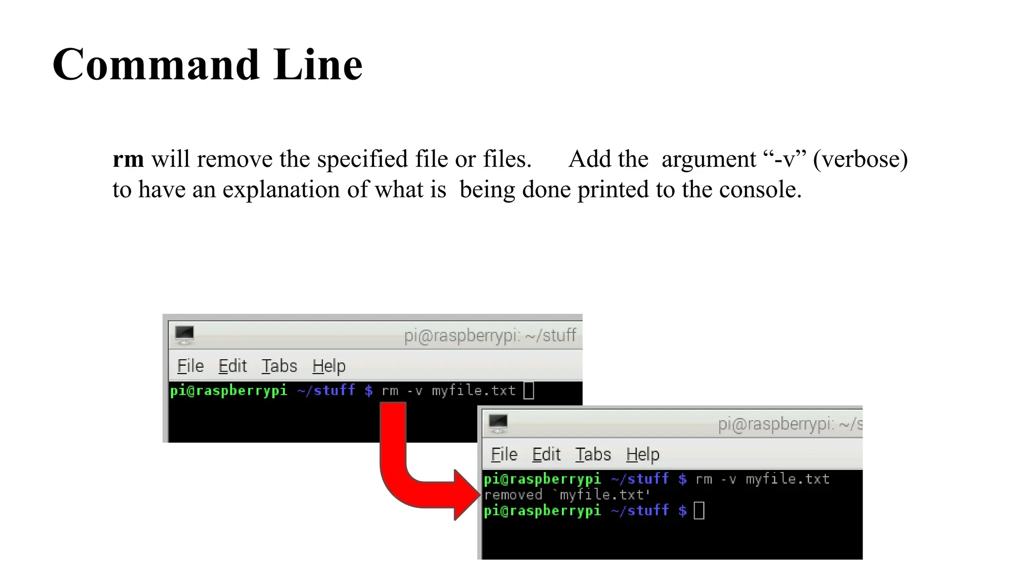
Internet of Things
(20CS002)
Department of Computer Science and Engineering
Vignan's Foundation for Science, Technology & Research
IoT building blocks
• Nodes: This block alludes to the collection of
information which is further shared over the
network and processed by an IoT system. This
can be carried out using sensors, which require
power in the form of heat, vibration, battery or
wireless power transfer.
• Gateway/Bridge/Router: This block is mainly
the transmission stage in which the information is
shared over the network with the help of servers,
to be processed further.
• Cloud: The cloud computing is a part of service
platform and enabler that involves handling,
breaking down data streams and forwarding the
data further for IoT applications.
Ref:A. Prasad and P. Chawda, "Power management factors and techniques for IoT design devices," 19th International Symposium on Quality
Electronic Design (ISQED), 2018, pp. 364-369, doi: 10.1109/ISQED.2018.8357314.​
IoT building blocks
Ref: https://www.scnsoft.com/blog/iot-architecture-in-a-nutshell-and-how-it-works
Block diagram of an IoT Device
Arduino
It's an open-source physical computing platform based on a simple microcontroller board, and a
development environment for writing software for the board.
Arduino Nano
Arduino Mega
Arduino LilyPad
Arduino Mini Arduino Leonardo
Arduino Uno
Arduino boards comparison
Ref: https://forum.core-electronics.com.au/t/arduino-boards-compared/167
Types of memory, Ref: https://www.electronicshub.org/types-of-memory-on-arduino/
Arduino UNO
Digital pins:
14 digital IO pins
6 are PWM pins (3, 5, 6, 9, 10, and 11)
Analog pins:
6 analog pins(A0, A1, A2, A3, A4, and A5)
Takes analog values as an input
What is analog ?​
•It is continuous range of voltage values (not just 0 or 5V)​
Why convert to digital ?​
•Because our microcontroller only understands digital.
Arduino: Integrated Development Environment
Following steps are required to setup an Arduino board
1. Power the board by connecting it to a PC via USB cable
2. Launch the Arduino IDE
3. Open the project
4. Select the Arduino board
5. Select the serial port
6. Upload the program to board
Structure of an Arduino code
1. Define Variables
2. Setting up
functions
3. Eternal loop
void setup()
{}
void loop()
{}
Setup function is run once, when the
microcontroller boots up or resets.
After setup function the processor moves
to run code inside the loop function. Code
inside loop function will be run over and
over until the microcontroller is shut
down.
int pin = 1;
Before going to the setup function
constant variables should be defined
Arduino C – Basic functions
pinMode(var1, var2) pinMode functions sets the mode of given pin. Var1 is
PIN number and var2 is the mode (INPUT, OUTPUT)
digitalWrite changes the status of the pin. var1 is PIN
number and var2 is the status (LOW, HIGH).
digitalWrite(var1, var2)
digitalRead(var1) digitalRead returns the current status (LOW, HIGH) of
the pin. var1 is PIN number
analogRead(var1) AnalogRead returns a 10-bit (by default) value equal to the
voltage of the pin relative to the analog reference voltage.
AnalogWrite sets a pin (var1) to a voltage relative to the
analog reference voltage equal to an 8-bit (by default) value.
analogWrite(var1, var2)
LED On/Off Program
int ledPin = 13; //Variable to store the pin number
void setup()
{
pinMode(ledPin, OUTPUT); //set ledPin as output
}
void loop()
{
digitalWrite(ledPin, HIGH); //LED ON
delay(1000); //Wait 1000ms
digitalWrite(ledPin, LOW); //LED OFF
delay(1000); //Wait 1000ms
}
Fading in and Fading Out (Analog or Digital?)
To create an analog signal, the microcontroller uses a technique called
Pulse Width Modulation (PWM). By varying the duty cycle, mimic an
“average” analog voltage.
Fading in and Fading Out (Analog or Digital?)
analogWrite(pin, val);
pin – refers to the OUTPUT pin
( 3, 5, 6, 9, 10, 11)
val – 8 bit value (0 – 255).
0 => 0V | 255 => 5V
Fading - Code
Fading - Code
Recommended Books
By
Simon Monk
By
John Boxall
By
Jeremy Blum
What is the Raspberry Pi?
• Affordable credit-card sized computer
• Plugs into a computer monitor or TV
• Uses standard keyboard and mouse
• Can browse the internet and play HD
video
• Can also interact with the outside
world!
Raspberry Pi Foundation
Educational charity based in the UK
The Foundation’s goal is to advance the
education of adults and children in the field of
computers, computer science, and related
subjects.
https://www.raspberrypi.org/about
Corral-García, J., Lemus-Prieto, F., González-Sánchez, J.L. and Pérez-Toledano, M.Á., 2019. Analysis of energy consumption and optimization
techniques for writing energy-efficient code. Electronics, 8(10), p.1192.
Raspberry Pi Models Comparison
Arduino vs Raspberry Pi
Raspberry Pi OS
•Raspbian ​
• Raspbian Linux is a Debian Wheezy port optimized for Raspberry Pi. ​
•Arch​
• Arch is an Arch Linux port for AMD devices.​
•Pidora​
• Pidora Linux is a Fedora Linux optimized for Raspberry Pi.​
•RaspBMC​
• RaspBMC is an XBMC media-center distribution for Raspberry Pi.​
•OpenELEC​
• OpenELEC is a fast and user-friendly XBMC media-center distribution.​
•RISC OS​
• RISC OS is a very fast and compact operating system.
Ref: https://raspberrytips.com/best-os-for-raspberry-pi/
Raspberry Pi
• A powerful feature of the Raspberry Pi is the row of GPIO (general-
purpose input/output) pins along the top edge of the board.
• "General Purpose Input/output." GPIO is a type of pin found on
an integrated circuit that does not have a specific function.
• While most pins have a dedicated purpose, such as sending a signal to
a certain component, the function of a GPIO pin is customizable and can
be controlled by software.
• A 40-pin GPIO header is found on all current Raspberry Pi boards
• Any of the GPIO pins can be designated (in software) as an input or output
pin and used for a wide range of purposes.
Raspberry Pi
• PWM (pulse-width modulation)
• PWM works by pulsating DC current and varying the amount of time
that each pulse stays 'on' to control the amount of current that flows to a device such as
an LED.
• Software PWM available on all pins
• Hardware PWM available on GPIO12, GPIO13, GPIO18, GPIO19
• Serial Peripheral Interface (SPI)
• A communication protocol used to transfer data between micro-computers like the
Raspberry Pi and peripheral devices(sensors or actuators).
• SPI0: MOSI (GPIO10); MISO (GPIO9); SCLK (GPIO11); CE0 (GPIO8), CE1 (GPIO7)
• SPI1: MOSI (GPIO20); MISO (GPIO19); SCLK (GPIO21); CE0 (GPIO18);
CE1 (GPIO17); CE2 (GPIO16)
• For example, SD card modules, RFID card reader modules, and 2.4 GHz wireless
transmitter/receivers all use SPI to communicate with microcontrollers.
• One unique benefit of SPI is the fact that data can be transferred without interruption.
Raspberry Pi
• I2C
• It is a useful bus that allows data exchange between microcontrollers and peripherals with a
minimum of wiring.
• Data: (GPIO2); Clock (GPIO3)
• EEPROM Data: (GPIO0); EEPROM Clock (GPIO1)
• Seen in projects that use OLED displays, barometric pressure sensors, or gyroscope
/accelerometer module.
• Serial
• The serial port is a low-level way to send data between the Raspberry Pi and another
computer system. This can be useful if you want the Raspberry Pi to control another device.
• TX (GPIO14); RX (GPIO15)
• UART stands for Universal Asynchronous Receiver/Transmitter
• DIY electronics projects to connect GPS modules, Bluetooth modules to your Raspberry Pi.
• A UART’s main purpose is to transmit and receive serial data.
• One of the best things about UART is that it only uses two wires to transmit data between
devices.
Raspberry Pi
Configuring the Pi
Installing the Operating System
The micro SD that you have comes pre-
installed with the Linux based Raspbian
OS. Raspbian is a fork of another Linux
distribution called Debian.
Configuring the Pi
Login: pi
Password: raspberry
How to log into the Raspberry Pi fo
r the first time
You won’t see the password as you ty
pe it. This is a Linux security feature.
Configuring the Raspberry Pi for the first time
Launch the Raspberry Pi Configuration Tool
~$ sudo raspi-config
Configuring the Pi
Setting the keyboard layout
1. Choose option 4 Internationalization
Options
Configuring the Pi
Setting the keyboard layout
2. Choose option I3 Change Keyboard Layout
Configuring the Pi
Setting the keyboard layout
3. Choose an appropriate US keyboard
type
Configuring the Pi
Setting the keyboard layout
4. Choose English (US) for keyboard
layout
Configuring the Pi
Setting special command keys for the keyboard
5. Choose the default for the keyboard layout
Configuring the Pi
Setting special command keys for the keyboard
6. Select No for the Control+Alt+Backspace
command
Configuring the Pi
Enabling the camera socket
7. Choose option 5 Enable
Camera
Configuring the Pi
Enabling the camera socket
8. Select Enable
Configuring the Pi
Configuring the Pi
Optional: Set to automatically boot to GUI
9. Choose option 3 Enable Boot to Desktop/Scratch
Configuring the Pi
Optional: Set to automatically boot to GUI
10. Select Log in as user ‘pi’ at the graphical desktop
then select Ok
Configuring the Pi
Exit the configuration tool
11. Select Finish
Configuring the Pi
Exit the configuration tool
12. Select Yes if prompted to
reboot
WiFi Setup
Login: pi
Password: raspberry
The Command Line
~$
Type the following command and press ENTER
~$ startx
WiFi Setup
The Raspbian Desktop
WiFi Setup
Confirm that the WiFi dongle has been detected
1. Click the LXTerminal button in the top left menu bar
2. Type the command below into the command line
~$ ifconfig
WiFi Setup
Confirm that the WiFi dongle has been detected
3. You should see wlan0 in the list
4. You can close the terminal by typing exit and pressing
ENTER if wlan0 is in the list
WiFi Setup
Connect to ND-Guest
5. Click the menu button find Preferences
6. From Preferences select WiFi Configuration
WiFi Setup
Connect to ND-Guest
7. Click the Scan button
8. Double click ND-Guest from the list
WiFi Setup
Connect to ND-Guest
9. Click on the Add
button without making
any changes to ND-
Guest
WiFi Setup
Connect to ND-Guest
10. Make sure ND-Guest
is the selected network
11. Click the Connect button
WiFi Setup
The Wifi connection should now be working
The WiFi Configuration Tool will be running in the
background. See it in the top right corner of your
screen.
Command Line
The command line gives you more control
Click on the LXTerminal button in the top left menu bar.
This will give you access to a console that can do
everything the GUI can and more.
Command Line
Echo will print the argument to the console.
Command Line
Man will show you the manual page for the argument.
Press Q on the keyboard to exit the manual page.
Command Line
Apropos is used to search the manual page descriptions for
the specified keyword. You can find commands with “copy”
in their descriptions as an example.
Command Line
Clear will move the prompt to the top of the console
window. This effectively clears the console.
Command Line
Pwd will print the current working directory path. This is basically “where
you are” with this console.
Command Line
ls list the directories in the current working directory.
Command Line
Most commands have options (arguments) that change their
behavior. The options usually start with a “-” and are typed
after the command.
~$ ls -a
Display hidden files
~$ ls -l List files in long format
Command Line
Using both “a” and “l” after the ls command.
Command Line
mkdir will create a new directory with the name you specify after the
command. Use mkdir and then use ls to see the directory created.
Command Line
Create and open a simple text file with leafpad myfile.txt
This creates a text file called myfile.txt and opens it in a text
editor called leafpad automatically.
Type a short message
Command Line
Use the ls command to see the new text file. If you want to
view the contents of the text file without opening LeafPad
back up, use the cat command followed by the file name.
Command Line
cp will copy your file to the specified directory. In this
example you can type ls /home/pi to see the copied file.
Command Line
rm will remove the specified file or files. Add the argument “-v” (verbose)
to have an explanation of what is being done printed to the console.
Command Line
Updating the Raspberry Pi
• Sudo means Super-User DO and is followed by a command that
requires the super-user to complete.
• Apt-get is a package manager that you use to install,
update, and upgrade your software.
• Wget is used to access files from the internet.
Command Line
Updating the Raspberry Pi
Use the following command to download a file I have prepared from the internet.
The file will be downloaded into your current
working directory.
~$ wget https:/www.dropbox.com/s/ pLmz498wo3kgnpj/ss2015.tar
Command Line
Updating the Raspberry Pi
A file called update-script.sh is in the ss2015 directory. This is
a shell script. It’s a text file that contains console
commands that will execute if you run the shell script. Type cat
update-script.sh to see the contents of the script.
~$ cat update-script.sh
Command Line
Updating the Raspberry Pi
Try to run the shell script by typing the following:
~$ ./update-script.sh
What did it do?
Command Line
Updating the Raspberry Pi
You need to set permissions for the shell script file. Type
ls -l to see the permissions for the files in ss2015.
R = read, W = write, X = execute
Owner Group World
r w x r w x r w x
Command Line
Updating the Raspberry Pi
File to have full permissions for the owner, and read/execute
permissions for all others. We use the chmod command to
accomplish this.
~$ chmod 755 update-script.sh
Command Line
Updating the Raspberry Pi
You can use ls -l to see that the file now has the proper
permissions.
-rwxr-xr-x
Command Line
Installing the Python Pi Camera module
To install this module type the following:
~$ sudo apt-get install python-picamera
If you are prompted to confirm any of your updates, just
press Y and then press ENTER.
Python and PiCamera
Controlling the Pi Camera with Python
Before Python execution, run this command in a console:
~$ raspistill -v -o ss2015.jpg
Python and PiCamera
Controlling the Pi Camera with Python
This command will take a picture with the Pi Camera using the default
settings. The picture will be called “ss2015.jpg”
(unless you called it something else).
The text that printed out are all options, can
control.
Python and PiCamera
Controlling the Pi Camera with Python
Lets launch IDLE from the console, which is an integrated
development environment for Python.
Python and PiCamera
Controlling the Pi Camera with Python
First, type import os and press ENTER so have access to operating system
functionality. This will let us
call the raspistill command from inside of IDLE with Python.
Python and PiCamera
Controlling the Pi Camera with Python
Call the same command we used earlier in the console. To do
that type the following: os.system(“raspistill -v -o hello.jpg”)
Python and PiCamera
Controlling the Pi Camera with Python
Now try using some of these options for the camera:
-w 600 –h 800 –q 70 –ifx cartoon
Python and PiCamera
Controlling the Pi Camera with Python
Take video with the camera: os.system(“raspivid -o myvideo.h264”)
Python and PiCamera
Controlling the Pi Camera with Python
Use this command to see a small preview of your video:
os.system(“omxplayer --win ‘0 0 320 240’ myvideo.h264”)
Or this to see it full size:
os.system(“omxplayer myvideo.h264”)
Python and PiCamera​
Options for the raspistill and raspivid commands
-o
-w
-h
-sh
-co
-br
-sa
-vf
-hf
output file name (-o picture.jpg or vid.h264)
width (-w 600)
height (-h 800)
sharpness, -100 to 100 (-sh 75)
contrast, -100 to 100 (-co 50)
brightness, 0 to 100 (-br 65)
saturation, -100 to 100 (-sa 85)
vertically flip image
horizontally flip image
Python and PiCamera​
•jpeg image quality, 0 to 100 (-q 70)
•image effects (-ifx negative, solarise, sketch,oilpaint, hatch, pastel, film,
watercolour, emboss, blur, cartoon, and more!)
Options for the raspistill and raspivid commands
-q
-ifx
There are many more options for the Pi Camera:
https://www.raspberrypi.org/documentation/raspbian
/applications/camera.md
Raspberry Pi
• To exit IDLE, type exit() and press ENTER or click the
X in the top right corner.
• To shutdown your Raspberry Pi select Shutdown from the
menu in the top left corner then press OK.

M.Tech Internet of Things Unit - III.pptx

  • 1.
    Internet of Things (20CS002) Departmentof Computer Science and Engineering Vignan's Foundation for Science, Technology & Research
  • 2.
    IoT building blocks •Nodes: This block alludes to the collection of information which is further shared over the network and processed by an IoT system. This can be carried out using sensors, which require power in the form of heat, vibration, battery or wireless power transfer. • Gateway/Bridge/Router: This block is mainly the transmission stage in which the information is shared over the network with the help of servers, to be processed further. • Cloud: The cloud computing is a part of service platform and enabler that involves handling, breaking down data streams and forwarding the data further for IoT applications. Ref:A. Prasad and P. Chawda, "Power management factors and techniques for IoT design devices," 19th International Symposium on Quality Electronic Design (ISQED), 2018, pp. 364-369, doi: 10.1109/ISQED.2018.8357314.​
  • 3.
    IoT building blocks Ref:https://www.scnsoft.com/blog/iot-architecture-in-a-nutshell-and-how-it-works
  • 4.
    Block diagram ofan IoT Device
  • 5.
    Arduino It's an open-sourcephysical computing platform based on a simple microcontroller board, and a development environment for writing software for the board. Arduino Nano Arduino Mega Arduino LilyPad Arduino Mini Arduino Leonardo Arduino Uno
  • 6.
    Arduino boards comparison Ref:https://forum.core-electronics.com.au/t/arduino-boards-compared/167 Types of memory, Ref: https://www.electronicshub.org/types-of-memory-on-arduino/
  • 7.
    Arduino UNO Digital pins: 14digital IO pins 6 are PWM pins (3, 5, 6, 9, 10, and 11) Analog pins: 6 analog pins(A0, A1, A2, A3, A4, and A5) Takes analog values as an input What is analog ?​ •It is continuous range of voltage values (not just 0 or 5V)​ Why convert to digital ?​ •Because our microcontroller only understands digital.
  • 8.
    Arduino: Integrated DevelopmentEnvironment Following steps are required to setup an Arduino board 1. Power the board by connecting it to a PC via USB cable 2. Launch the Arduino IDE 3. Open the project 4. Select the Arduino board 5. Select the serial port 6. Upload the program to board
  • 9.
    Structure of anArduino code 1. Define Variables 2. Setting up functions 3. Eternal loop void setup() {} void loop() {} Setup function is run once, when the microcontroller boots up or resets. After setup function the processor moves to run code inside the loop function. Code inside loop function will be run over and over until the microcontroller is shut down. int pin = 1; Before going to the setup function constant variables should be defined
  • 10.
    Arduino C –Basic functions pinMode(var1, var2) pinMode functions sets the mode of given pin. Var1 is PIN number and var2 is the mode (INPUT, OUTPUT) digitalWrite changes the status of the pin. var1 is PIN number and var2 is the status (LOW, HIGH). digitalWrite(var1, var2) digitalRead(var1) digitalRead returns the current status (LOW, HIGH) of the pin. var1 is PIN number analogRead(var1) AnalogRead returns a 10-bit (by default) value equal to the voltage of the pin relative to the analog reference voltage. AnalogWrite sets a pin (var1) to a voltage relative to the analog reference voltage equal to an 8-bit (by default) value. analogWrite(var1, var2)
  • 11.
    LED On/Off Program intledPin = 13; //Variable to store the pin number void setup() { pinMode(ledPin, OUTPUT); //set ledPin as output } void loop() { digitalWrite(ledPin, HIGH); //LED ON delay(1000); //Wait 1000ms digitalWrite(ledPin, LOW); //LED OFF delay(1000); //Wait 1000ms }
  • 12.
    Fading in andFading Out (Analog or Digital?) To create an analog signal, the microcontroller uses a technique called Pulse Width Modulation (PWM). By varying the duty cycle, mimic an “average” analog voltage.
  • 13.
    Fading in andFading Out (Analog or Digital?) analogWrite(pin, val); pin – refers to the OUTPUT pin ( 3, 5, 6, 9, 10, 11) val – 8 bit value (0 – 255). 0 => 0V | 255 => 5V
  • 14.
  • 15.
  • 16.
  • 17.
    What is theRaspberry Pi? • Affordable credit-card sized computer • Plugs into a computer monitor or TV • Uses standard keyboard and mouse • Can browse the internet and play HD video • Can also interact with the outside world!
  • 18.
    Raspberry Pi Foundation Educationalcharity based in the UK The Foundation’s goal is to advance the education of adults and children in the field of computers, computer science, and related subjects. https://www.raspberrypi.org/about
  • 19.
    Corral-García, J., Lemus-Prieto,F., González-Sánchez, J.L. and Pérez-Toledano, M.Á., 2019. Analysis of energy consumption and optimization techniques for writing energy-efficient code. Electronics, 8(10), p.1192. Raspberry Pi Models Comparison
  • 20.
  • 21.
    Raspberry Pi OS •Raspbian​ • Raspbian Linux is a Debian Wheezy port optimized for Raspberry Pi. ​ •Arch​ • Arch is an Arch Linux port for AMD devices.​ •Pidora​ • Pidora Linux is a Fedora Linux optimized for Raspberry Pi.​ •RaspBMC​ • RaspBMC is an XBMC media-center distribution for Raspberry Pi.​ •OpenELEC​ • OpenELEC is a fast and user-friendly XBMC media-center distribution.​ •RISC OS​ • RISC OS is a very fast and compact operating system. Ref: https://raspberrytips.com/best-os-for-raspberry-pi/
  • 22.
  • 23.
    • A powerfulfeature of the Raspberry Pi is the row of GPIO (general- purpose input/output) pins along the top edge of the board. • "General Purpose Input/output." GPIO is a type of pin found on an integrated circuit that does not have a specific function. • While most pins have a dedicated purpose, such as sending a signal to a certain component, the function of a GPIO pin is customizable and can be controlled by software. • A 40-pin GPIO header is found on all current Raspberry Pi boards • Any of the GPIO pins can be designated (in software) as an input or output pin and used for a wide range of purposes. Raspberry Pi
  • 24.
    • PWM (pulse-widthmodulation) • PWM works by pulsating DC current and varying the amount of time that each pulse stays 'on' to control the amount of current that flows to a device such as an LED. • Software PWM available on all pins • Hardware PWM available on GPIO12, GPIO13, GPIO18, GPIO19 • Serial Peripheral Interface (SPI) • A communication protocol used to transfer data between micro-computers like the Raspberry Pi and peripheral devices(sensors or actuators). • SPI0: MOSI (GPIO10); MISO (GPIO9); SCLK (GPIO11); CE0 (GPIO8), CE1 (GPIO7) • SPI1: MOSI (GPIO20); MISO (GPIO19); SCLK (GPIO21); CE0 (GPIO18); CE1 (GPIO17); CE2 (GPIO16) • For example, SD card modules, RFID card reader modules, and 2.4 GHz wireless transmitter/receivers all use SPI to communicate with microcontrollers. • One unique benefit of SPI is the fact that data can be transferred without interruption. Raspberry Pi
  • 25.
    • I2C • Itis a useful bus that allows data exchange between microcontrollers and peripherals with a minimum of wiring. • Data: (GPIO2); Clock (GPIO3) • EEPROM Data: (GPIO0); EEPROM Clock (GPIO1) • Seen in projects that use OLED displays, barometric pressure sensors, or gyroscope /accelerometer module. • Serial • The serial port is a low-level way to send data between the Raspberry Pi and another computer system. This can be useful if you want the Raspberry Pi to control another device. • TX (GPIO14); RX (GPIO15) • UART stands for Universal Asynchronous Receiver/Transmitter • DIY electronics projects to connect GPS modules, Bluetooth modules to your Raspberry Pi. • A UART’s main purpose is to transmit and receive serial data. • One of the best things about UART is that it only uses two wires to transmit data between devices. Raspberry Pi
  • 26.
    Configuring the Pi Installingthe Operating System The micro SD that you have comes pre- installed with the Linux based Raspbian OS. Raspbian is a fork of another Linux distribution called Debian.
  • 27.
    Configuring the Pi Login:pi Password: raspberry How to log into the Raspberry Pi fo r the first time You won’t see the password as you ty pe it. This is a Linux security feature.
  • 28.
    Configuring the RaspberryPi for the first time Launch the Raspberry Pi Configuration Tool ~$ sudo raspi-config Configuring the Pi
  • 29.
    Setting the keyboardlayout 1. Choose option 4 Internationalization Options Configuring the Pi
  • 30.
    Setting the keyboardlayout 2. Choose option I3 Change Keyboard Layout Configuring the Pi
  • 31.
    Setting the keyboardlayout 3. Choose an appropriate US keyboard type Configuring the Pi
  • 32.
    Setting the keyboardlayout 4. Choose English (US) for keyboard layout Configuring the Pi
  • 33.
    Setting special commandkeys for the keyboard 5. Choose the default for the keyboard layout Configuring the Pi
  • 34.
    Setting special commandkeys for the keyboard 6. Select No for the Control+Alt+Backspace command Configuring the Pi
  • 35.
    Enabling the camerasocket 7. Choose option 5 Enable Camera Configuring the Pi
  • 36.
    Enabling the camerasocket 8. Select Enable Configuring the Pi
  • 37.
    Configuring the Pi Optional:Set to automatically boot to GUI 9. Choose option 3 Enable Boot to Desktop/Scratch
  • 38.
    Configuring the Pi Optional:Set to automatically boot to GUI 10. Select Log in as user ‘pi’ at the graphical desktop then select Ok
  • 39.
    Configuring the Pi Exitthe configuration tool 11. Select Finish
  • 40.
    Configuring the Pi Exitthe configuration tool 12. Select Yes if prompted to reboot
  • 41.
    WiFi Setup Login: pi Password:raspberry The Command Line ~$ Type the following command and press ENTER ~$ startx
  • 42.
  • 43.
    WiFi Setup Confirm thatthe WiFi dongle has been detected 1. Click the LXTerminal button in the top left menu bar 2. Type the command below into the command line ~$ ifconfig
  • 44.
    WiFi Setup Confirm thatthe WiFi dongle has been detected 3. You should see wlan0 in the list 4. You can close the terminal by typing exit and pressing ENTER if wlan0 is in the list
  • 45.
    WiFi Setup Connect toND-Guest 5. Click the menu button find Preferences 6. From Preferences select WiFi Configuration
  • 46.
    WiFi Setup Connect toND-Guest 7. Click the Scan button 8. Double click ND-Guest from the list
  • 47.
    WiFi Setup Connect toND-Guest 9. Click on the Add button without making any changes to ND- Guest
  • 48.
    WiFi Setup Connect toND-Guest 10. Make sure ND-Guest is the selected network 11. Click the Connect button
  • 49.
    WiFi Setup The Wificonnection should now be working The WiFi Configuration Tool will be running in the background. See it in the top right corner of your screen.
  • 50.
    Command Line The commandline gives you more control Click on the LXTerminal button in the top left menu bar. This will give you access to a console that can do everything the GUI can and more.
  • 51.
    Command Line Echo willprint the argument to the console.
  • 52.
    Command Line Man willshow you the manual page for the argument. Press Q on the keyboard to exit the manual page.
  • 53.
    Command Line Apropos isused to search the manual page descriptions for the specified keyword. You can find commands with “copy” in their descriptions as an example.
  • 54.
    Command Line Clear willmove the prompt to the top of the console window. This effectively clears the console.
  • 55.
    Command Line Pwd willprint the current working directory path. This is basically “where you are” with this console.
  • 56.
    Command Line ls listthe directories in the current working directory.
  • 57.
    Command Line Most commandshave options (arguments) that change their behavior. The options usually start with a “-” and are typed after the command. ~$ ls -a Display hidden files ~$ ls -l List files in long format
  • 58.
    Command Line Using both“a” and “l” after the ls command.
  • 59.
    Command Line mkdir willcreate a new directory with the name you specify after the command. Use mkdir and then use ls to see the directory created.
  • 60.
    Command Line Create andopen a simple text file with leafpad myfile.txt This creates a text file called myfile.txt and opens it in a text editor called leafpad automatically. Type a short message
  • 61.
    Command Line Use thels command to see the new text file. If you want to view the contents of the text file without opening LeafPad back up, use the cat command followed by the file name.
  • 62.
    Command Line cp willcopy your file to the specified directory. In this example you can type ls /home/pi to see the copied file.
  • 63.
    Command Line rm willremove the specified file or files. Add the argument “-v” (verbose) to have an explanation of what is being done printed to the console.
  • 64.
    Command Line Updating theRaspberry Pi • Sudo means Super-User DO and is followed by a command that requires the super-user to complete. • Apt-get is a package manager that you use to install, update, and upgrade your software. • Wget is used to access files from the internet.
  • 65.
    Command Line Updating theRaspberry Pi Use the following command to download a file I have prepared from the internet. The file will be downloaded into your current working directory. ~$ wget https:/www.dropbox.com/s/ pLmz498wo3kgnpj/ss2015.tar
  • 66.
    Command Line Updating theRaspberry Pi A file called update-script.sh is in the ss2015 directory. This is a shell script. It’s a text file that contains console commands that will execute if you run the shell script. Type cat update-script.sh to see the contents of the script. ~$ cat update-script.sh
  • 67.
    Command Line Updating theRaspberry Pi Try to run the shell script by typing the following: ~$ ./update-script.sh What did it do?
  • 68.
    Command Line Updating theRaspberry Pi You need to set permissions for the shell script file. Type ls -l to see the permissions for the files in ss2015. R = read, W = write, X = execute Owner Group World r w x r w x r w x
  • 69.
    Command Line Updating theRaspberry Pi File to have full permissions for the owner, and read/execute permissions for all others. We use the chmod command to accomplish this. ~$ chmod 755 update-script.sh
  • 70.
    Command Line Updating theRaspberry Pi You can use ls -l to see that the file now has the proper permissions. -rwxr-xr-x
  • 71.
    Command Line Installing thePython Pi Camera module To install this module type the following: ~$ sudo apt-get install python-picamera If you are prompted to confirm any of your updates, just press Y and then press ENTER.
  • 72.
    Python and PiCamera Controllingthe Pi Camera with Python Before Python execution, run this command in a console: ~$ raspistill -v -o ss2015.jpg
  • 73.
    Python and PiCamera Controllingthe Pi Camera with Python This command will take a picture with the Pi Camera using the default settings. The picture will be called “ss2015.jpg” (unless you called it something else). The text that printed out are all options, can control.
  • 74.
    Python and PiCamera Controllingthe Pi Camera with Python Lets launch IDLE from the console, which is an integrated development environment for Python.
  • 75.
    Python and PiCamera Controllingthe Pi Camera with Python First, type import os and press ENTER so have access to operating system functionality. This will let us call the raspistill command from inside of IDLE with Python.
  • 76.
    Python and PiCamera Controllingthe Pi Camera with Python Call the same command we used earlier in the console. To do that type the following: os.system(“raspistill -v -o hello.jpg”)
  • 77.
    Python and PiCamera Controllingthe Pi Camera with Python Now try using some of these options for the camera: -w 600 –h 800 –q 70 –ifx cartoon
  • 78.
    Python and PiCamera Controllingthe Pi Camera with Python Take video with the camera: os.system(“raspivid -o myvideo.h264”)
  • 79.
    Python and PiCamera Controllingthe Pi Camera with Python Use this command to see a small preview of your video: os.system(“omxplayer --win ‘0 0 320 240’ myvideo.h264”) Or this to see it full size: os.system(“omxplayer myvideo.h264”)
  • 80.
    Python and PiCamera​ Optionsfor the raspistill and raspivid commands -o -w -h -sh -co -br -sa -vf -hf output file name (-o picture.jpg or vid.h264) width (-w 600) height (-h 800) sharpness, -100 to 100 (-sh 75) contrast, -100 to 100 (-co 50) brightness, 0 to 100 (-br 65) saturation, -100 to 100 (-sa 85) vertically flip image horizontally flip image
  • 81.
    Python and PiCamera​ •jpegimage quality, 0 to 100 (-q 70) •image effects (-ifx negative, solarise, sketch,oilpaint, hatch, pastel, film, watercolour, emboss, blur, cartoon, and more!) Options for the raspistill and raspivid commands -q -ifx There are many more options for the Pi Camera: https://www.raspberrypi.org/documentation/raspbian /applications/camera.md
  • 82.
    Raspberry Pi • Toexit IDLE, type exit() and press ENTER or click the X in the top right corner. • To shutdown your Raspberry Pi select Shutdown from the menu in the top left corner then press OK.

Editor's Notes

  • #8 Be sure to point out the what all of the buttons do.
  • #9 Be sure to point out the what all of the buttons do.
  • #11 INPUT_PULLUP uses an internal pullup resistor: Unlike pinMode(INPUT), there is no pull-down resistor necessary. An internal  20K-ohm resistor is pulled to 5V. This configuration causes the input to  read HIGH when the switch is open, and LOW when it is closed. Explain about the need of a pull-up or pull-down resistor