Download as PDF, PPTX

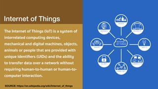

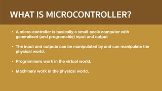


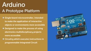


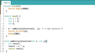

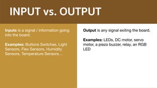
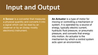
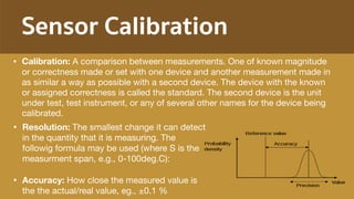
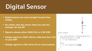
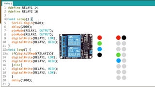
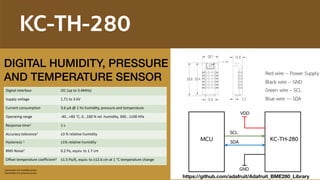


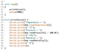


The document discusses using Internet of Things (IoT) technology for smart agriculture. It provides an overview of IoT and how devices can communicate over a network without human interaction. It then discusses how microcontrollers like Arduino can be used to interface with sensors and actuators to monitor and control the physical environment for applications like smart farming. The document provides examples of using sensors to collect environmental data and controlling devices like motors and lights through a microcontroller.