National Roads
Provincial Roads
(Section 2)
Provincial roads are those which connect
municipal roads or which are located within
the province but do not form continuous
sections of national roads.
City Roads
(Section 3)
City roads are those located within the city
limits.
Municipal Roads
(Section 4)
Municipal roads are those located within the
municipal limits but outside of city limits.
Barangay Roads
(Section 5)
Barangay roads are those located within the
barangay limits.
National Roads - These are roads that connect
regions, provinces and highly urbanized cities.
They form the backbone of the national road


![1. Local Development Planning Framework in
the Philippines
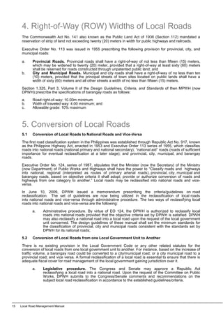
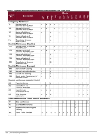
National and local development planning has evolved from a master planning approach towards a
more strategic planning process. Anchored on a more consultative process, most government agencies
(NGAs) and local government units (LGUs) have adopted the strategic planning approach in their
respective planning processes. Strategic planning is a process where the vision of the planning area is
defined for the preferred future environment of the locality, which is normally arrived at as a consensus
amongst the stakeholders. Strategies are developed to achieve the vision based on opportunities and
constraints of the planning environment (see Table 3.1). The strategies are operationalized through
policies, programs, projects and activities, which should lead to the attainment of the vision in the long term.
There is then monitoring and review of strategies and implemented actions to assess how the strategies
are performed based on the planning environment.
Local road planning is a component of the over-all local development planning process the local
governments as guided and assisted by oversight national government agencies. There are two basic
plans that local government units (LGUs) are mandated to prepare in accordance with Republic
Act No. 7160 (RA 7160), otherwise known as the Local Government Code (LGC) of 1991. These
plans are the Comprehensive Land Use Plan (CLUP) and the Comprehensive Development Plan (CDP).
The CLUP is the plan for the management of local territories by LGUs as embodied in the RA7160 (Section
20c, 447, 458, 468). The CDP is the plan with which the LGU promotes the general welfare of its
inhabitants in its capacity as a corporate body as mandated in RA 7160 (Sec. 106 and 109).
The local development planning process were harmonized under the Joint Memorandum Circular (JMC)
No. 1, which was issued on 8 March 2007 by the Department of the Interior and Local Government
(DILG), National Economic and Development Authority (NEDA), Department of Budget and Management
(DBM) and Department of Finance (DOF). JMC No. 1 strengthened the interface between LGUs and
national government agencies (with oversight functions on LGUs) including the complementation between
and among all LGU levels in local planning, investment programming, revenue administration, budgeting,
and expenditure management. Under these harmonization initiatives, the National Government has
recommended the integration of CLUP and CDP at the provincial level. The CLUP at the provincial level
was referred to before as the Provincial Physical Framework Plan (PPFP).
The CDP for provinces was called as the Provincial Development Plan (PDP). The National Government
through NEDA has since recommended the integration of PPFP and PDP into the Provincial Development
and Physical Framework Plan (PDPFP). NEDA in partnership with other oversight agencies has issued a
guideline for the preparation of PDPFP (called as the Guidelines for Provincial Local Planning and
Expenditure Management [PLPEM]). NEDA has been providing technical assistance to the provinces for
the preparation of the PDPFPs. The planning framework of PDPFP using the strategic planning approach
as recommended by the NEDA PLPEM Guidelines is shown in Figure 3.1.
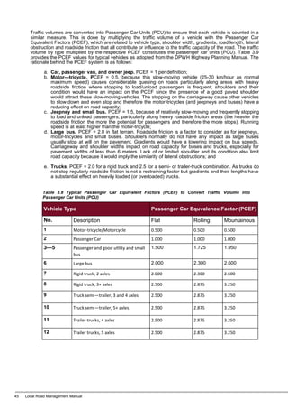
Components Description
Vision Where do you want to be in a particular time?
The preferred future environment
Existing Condition Where are you now?
The existing/current environment/situation
Strategy How do you achieve your vision?
Policies and actions to achieve the vision based on
analysis of opportunities and constraints, and the analy-
sis of projections and scenarios for the future
Monitoring How is the strategy performing given changing cir-
cumstances?
Monitoring and Review
Table 3.1 Strategic Planning Framework
Chapter 3: Local Road Planning 22](https://image.slidesharecdn.com/lrmmanualfinal-240213204708-c6766949/85/LRM-Manual-FINAL-pdf-29-320.jpg)


![1. Local Road Management Process
Through devolution and decentralization, LGUs have been granted with the local autonomy including the
efficient and effective provision of basic services and facilities. Local road infrastructures are considered
by the Local Government Code [Sections 17 (a) and (b)] as basic facilities that the LGUs should provide
within its jurisdiction. The development and management of the local road network is therefore central to
this mandate. As LGUs look to the National Government for guidance, it is paramount that recognized
practices for Local Road Management are shared to the LGUs as they fulfill their mandate.
Local Road Management (LRM), as the name implies, is planning and sustainably managing the local
road network in consideration of the envisioned socioeconomic development of the LGU. Sustainable
management of local road infrastructure requires regular maintenance, suitable prioritization and
planning, sufficient budget and adequate contracting, financial management and monitoring procedures.
In simple terms, Local Road Management (LRM) is the planning and implementation of investments to
local roads based on the function and condition of the local road viewed as a network that supports the
over-all socioeconomic development of the LGU. The DILG LRM Manual, thus, provides a simple
technical reference for LGUs on how they can ably plan and manage their local road network.
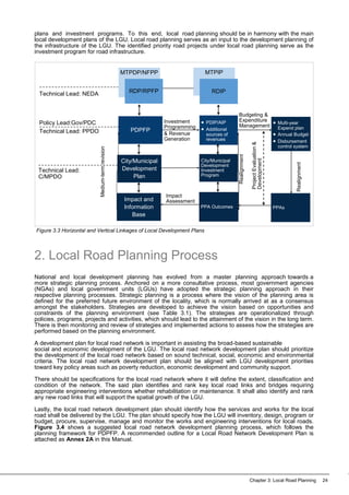
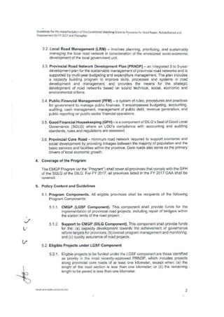
The local engineering offices will be faced with a series of decisions on what is the appropriate type of
investment (or civil works) to a local road and the best method to get this done effectively and efficiently.
In this context, an effective provision of a local road infrastructure means that the civil works
implemented to the local road functioned as planned, for which the local road is now providing a certain
level of service. On the other hand, an efficient provision of local road infrastructure refers to delivering
such civil works to a local road at the least cost without sacrificing quality and safety. The local
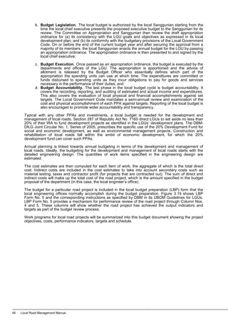
engineering offices can be guided by the local road management process chart shown in Figure 4.1. The
stages in this LRM process chart are:
a. Configuration of the Local Road Network. All LGUs have an envisioned socioeconomic
development that is to be attained in the medium or long-term period. The local roads should
be configured as a network supporting this envisioned development of the LGU. As discussed
in the previous chapter, some local roads provide more primary function to the network and
some local roads serve secondary roles. Cities and municipalities should refer to their
Comprehensive Land Use Plan (CLUP), whereas provinces should refer to their Provincial
Development and Physical Framework Plan (PDPFP) in configuring their local road network;
b. Local Road Condition Inventory. The previous step defines the local road network in terms of
which local roads are primary (or critical) and which are secondary (noncritical), the physical
conditions of these local roads should be thoroughly inventoried. The detailed condition
describes the local road if it is in functioning as intended, if it needs to be rehabilitated or
improved first, or if it is already in maintainable condition. The system of local road condition
inventory has been discussed in the previous chapter. But in general, local roads in good to fair
condition are in maintainable condition. Adequate maintenance works should be planned and
implemented to these local roads to prevent rapid deterioration. Meanwhile, local roads
classified as in poor to bad condition should be rehabilitated first into a maintainable condition.
Local roads in poor to bad condition that have been given maintenance works will certainly lead
to rapid deterioration as the level of work items may not be sufficient enough to make the
subject road in good to fair condition. The local road condition inventory also includes the
determination of the level of traffic volume on a given local road. Obviously, if the capacity of
the local road is not sufficient to handle the present and future traffic volume, then investments
have to be implemented unto the subject road either by improving the geometric conditions of
the road or by upgrading the pavement of the road to accommodate the expected traffic
volume. Local road inventories should also include the identification of road right-of-way issues
including the appropriate measures to resolve these issues;
Chapter 4: Local Road Surface Treatment Options 52](https://image.slidesharecdn.com/lrmmanualfinal-240213204708-c6766949/85/LRM-Manual-FINAL-pdf-59-320.jpg)


![Chapter 5: Local Road Quantity Calculation and Cost Estimation 74
j. Minor Tools. Minor equipment and tools which are not reflected in the ACEL
Equipment Guidebook may be taken from the latest rental rate schedule of the
DPWH Bureau of Equipment. Hand tools (minor tools) such as wheelbarrows, pails,
shovels, picks, scaffolds, poles, board, etc. and other small tools of non-mechanized
in nature which are necessary in the execution of works are expressed as a
percentage of labor cost and usually ranges from 5% to 10%.
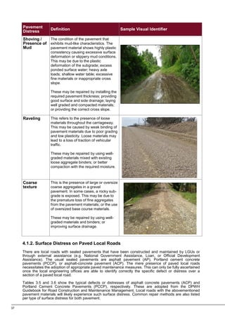
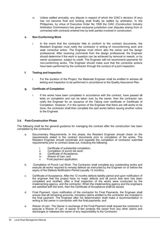
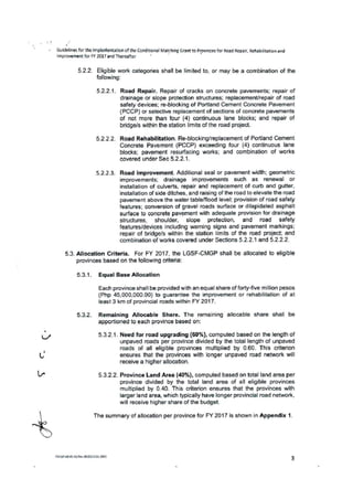
4.1.4 Total Project Estimate
The Construction cost for the package is estimated by using the unit prices computed and the
quantities calculated in the same prescribed format for the Calculation of Approved Budget for the
Contract (see Table 5.3 with the corresponding computations for each column). The total for each
Bid Part or Bill Item of this cost estimate is carried to the Summary of Costs and the total project
cost is compiled in the Total Project Estimate, which is the Approved Budget for the Contract
(ABC) issued in the advertisements. A Program of Works should be prepared based on the ABC,
the standard form of POW shall conform to DPWH DO #163 – Series of 2015. Provision for
Dayworks and Contigencies amounting to 10% of project maybe added to project cost if
necessary. Sample quantity calculation templates are attached as Annex 4A, while sample cost
estimation templates are shown in Annex 4B
4.2 Road Works by Administration
There are instances where local engineering offices will undertake local road works By Administration or
Force account; By Administration process can be done only if there is a failure of bidding due to reasons
beyond IA control, emergency situation, peace and order in the project site, provided that the concern
LGU is financially and technically capable to implement the project. Provided further that the said LGU
has implemented a similar project with a cost equivalent to 50% of the proposed projects. Assessment
of such shall be conducted by DPWH. whether these are new road construction, rehabilitation,
maintenance, improvement or upgrading. However, it is understood that accounting for such projects
shall be within the government usual accounting and auditing process. Labor costs shall fall under
Government salary/wages standards. The threshold amount for labor will depend on LGU category or
Classification. (please refer to Annex 1 of RA 9184 and its IRR – Guidelines in the Implementation of
Projects by Administration
4.2.1 Direct Costs
The Direct Costs for By-Administration Road Works shall follow the DPWH DO # 197- Series
2016. These direct costs should similarly include:
a. Material Costs. If the material source (quarry source) is owned by the LGU,
materials cost should be accounted or priced for auditing purposes, although the
costs are zero if project is implemented. However, if the quarry source is privately-
owned, the material costs should follow prevailing market rates;
Item
No.
Work
Item
(Pay
Item)
Quantity Unit
Estimated
Direct
Cost
Mark-Up in
Percent
Total Mark-Up
VAT
Total
Indirect
Cost
Total
Cost
Unit
Cost
OC
M
Profit % Value
(1) (2) (3) (4) (5) (6) (7)
(8) =
(6) +
(7)
(9) =
(5) x
(8)
(10) =
12% x [(5) + (9)]
(11) =
(9) + (10)
(12) =
(5) + (11)
(13) =
(12) / (3)
TOTAL COST](https://image.slidesharecdn.com/lrmmanualfinal-240213204708-c6766949/85/LRM-Manual-FINAL-pdf-81-320.jpg)


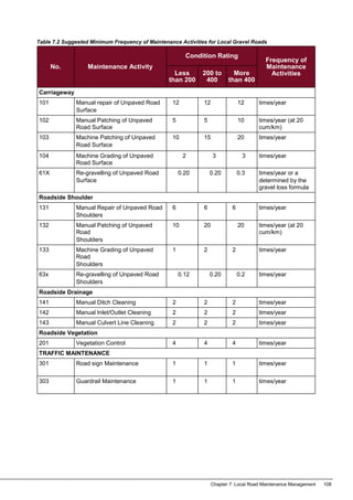

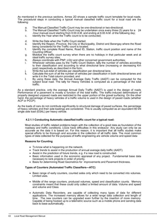
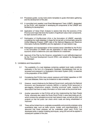
![In contrast, periodic maintenance for paved roads will require more work items on a wider coverage at
fewer frequencies than routine maintenance. Periodic maintenance seeks to preserve the quality of the
sealed pavement at whole sections. Cost estimates for the maintenance of sealed pavements will also
require the same degree of quantity calculation and cost estimation as gravel road maintenance (see
previous section). Unlike gravel roads, the maintenance of sealed pavements are based on the
inspection findings for sections showing pavement defects or distress (see the section on local road
inventory at the local road planning chapter of this manual). Maintenance measures are then based on
the degree of distress over the pavement.
Tables 7.5 to 7.8 show the typical procedural activities for the maintenance of asphalt pavement. On the
other hand, work activities for the maintenance of concrete pavement are shown in Tables 7.9 to 7.11.
These procedural steps for the maintenance activities of sealed pavement (asphalt and concrete) are
adopted from the Road Maintenance Guidelines of DPWH.
Item
No.
Work
Item
(Pay
Item)
Quantity Unit
Estimated
Direct
Cost
Mark-up in
Percent
Total Mark-up
VAT
Total
Indirect
Cost
Total
Cost
Unit
Cost
OCM Profit % Value
(1) (2) (3) (4) (5) (6) (7)
(8) =
(6) + (7)
(9) =
(5) x (8)
(10) =
12% x [(5) +
(9)]
(11) =
(9) +
(10)
(12) =
(5) +
(11)
(13) =
(12) /
(3)
Total Cost
111 Local Road Management Manual
Purpose
To eliminate hazardous conditions and to provide smooth, well-drained surfaces.
Procedure
1. Remove standing water and temporary patching material from defect or area to be leveled.
2. Shape defects so that; (a) depth provides for sufficient strength; (b) sides are vertical; (c) corners
are square or slightly rounded; (d) sides have no abrupt changes in line; and (e) hole is cut back
into sound pavement.
3. Add base material if needed.
4. Clean and tack defects or area to be leveled.
5. Place premix in layers and compact each layer. Mix should be placed only within limits of hole
and area to be leveled.
6. Final layer should be flushed with surrounding surface.
7. Dig channels through shoulders, if needed, to allow water to drain.
8. Check cross section, profile and drainage. Rework if needed.
Notes
• Materials to be used should be dense graded asphalt mixture with maximum grain size equal to
or less than 19 mm.
• Wet part should be heated to be dried with burner.
• Laying of asphalt mixture should be approx. 1 cm. higher than the adjacent surroundings to give
allowance for settlement.
• When depth of pothole is more than 7 cm, compact mixture in two layers.
Table 7.5 Premix Patching Bituminous Pavements](https://image.slidesharecdn.com/lrmmanualfinal-240213204708-c6766949/85/LRM-Manual-FINAL-pdf-118-320.jpg)


![K. VULNERABILITY TO
FLOODING2
Approx. distance from bodies of
water (e.g lakes, bay, sea):
less than 5 meters
5m to less than 1 km
km to less than 10 km
greater than 10 km
Within low-lying area:
(0)Yes No
Score (S) :_________________
(May be vulnerable to Flooding Hazard if S < 4)
L. VULNERABILITY TO OTHER
HAZARDS2
Within typhoon-prone area :
(0)Yes (1)No
Within 20km radius of active
volcano :
(0)Yes (1)No
Within 10km from garbage dumping
area:
(0)Yes (1)No
Score (S) :__________
(May be vulnerable if S =0 on the identified hazard )
M. Remarks on Hazards
N. BRIDGE STRUCTURAL AND OTHER COMPONENTS
COMPONENTS PHOTOS COMPONENTS PHOTOS
Slab deck:
Timber
Steel plate
Reinforced concrete
Abutments and Wing Walls:
Reinforced concrete
Other: __________
Beams and Girders:
Timber
Structural steel
Reinforced concrete
Prestressed concrete
Railings:
Reinforced con-
crete Steel:
Other: _________ Rail
posts:
Reinforced con-
crete Steel:
Other:__________
Columns and Piers:
Timber
Structural steel
Reinforced concrete
Pre-stressed concrete
Others :
2
Hazard rating are indicated in parenthesis ( ).
3
This assessment form streamlines the information derived from the DILG-developed assessment form and FEMA Handbook 154.
This assessment is aimed mainly at screening buildings for potential seismic hazard, and not to determine the present condition of the structure.
4
[1200ft/s < measured shear wave velocity,Vs ≤ 2500ft/s] OR [SPT N > 50] OR [Undrained Shear Strength, Su > 2000psf]
5
[600ft/s < Vs ≤ 1200ft/s] OR [15<SPT N≤ 50] OR [1000psf< Su≤ 2000psf]
6
[Vs ≤ 600ft/s] OR [Soil > 100ft deep w/ Plasticity Index > 20, Water content > 40%, and Su < 500 psf]
III. VISUAL SCREENING OF BRIDGES FOR POTENTIAL SEISMIC HAZARDS
(AFTER FEMA HANDBOOK 154 for High Seismicity Regions: If Final Score < 2.0, structure may be vulnerable to Seismic Hazards)3
TYPE OF CONSTRUCTION TIMBER STEEL CONCRETE
A. Basic Score
Single span OR 3.8 3.2 2.5
2 to 3 spans OR 3.8 3.2 2.9
More than 3 spans 3.8 3.2 3.1
B. Vertical Irregularity -2.0 N/A -1.5
C. Plan Irregularity -0.5 -0.5 -0.5
D. Age of bridge structure
Pre-Code (constructed before 1972) -1.0 -0.6 -1.2
Post Benchmark (constructed after 1992) +2.4 N/A +1.4
E. Soil Type
Soil Type C4
(Soft Rock/Very Dense Soil) -0.4 -0.4 -0.4
Soil Type D5
(Stiff Soil, OR if No Data assume for all 1-3-span
bridge)
-0.8 -0.6 -0.6
Soil Type E6
(Soft Soil, OR if No Data assume for all bridges >3
spans)
-0.8 -1.0 -1.2
FINAL SCORE, S (If less than 2.0, bridge structure may be vulnerable to Seismic Hazards)](https://image.slidesharecdn.com/lrmmanualfinal-240213204708-c6766949/85/LRM-Manual-FINAL-pdf-295-320.jpg)


