This document describes the design of a low-cost 60 GHz switched-beam smart antenna receiver subsystem based on substrate integrated waveguide (SIW) technology. Key elements of the design include:
1) An integrated antenna array, Butler matrix, and bandpass filter fabricated on a single substrate to overcome interconnection challenges at millimeter-wave frequencies.
2) A sub-harmonically pumped mixer that downconverts 60 GHz signals to an intermediate frequency of 1.5 GHz using a lower-cost 30 GHz local oscillator instead of a 60 GHz LO.
3) A digital signal processing system that compares the four intermediate frequency signals to determine the maximum power and switch the antenna beam accordingly to track the incoming
![1156 IEEE TRANSACTIONS ON MICROWAVE THEORY AND TECHNIQUES, VOL. 60, NO. 4, APRIL 2012
Low-Cost 60-GHz Smart Antenna Receiver
Subsystem Based on Substrate
Integrated Waveguide Technology
Fan Fan He, Ke Wu, Fellow, IEEE, Wei Hong, Senior Member, IEEE, Liang Han, and Xiao-Ping Chen
Abstract—In this paper, a low-cost integrated 60-GHz switched-
beam smart antenna subsystem is studied and demonstrated ex-
perimentally for the first time based on almost all 60-GHz sub-
strate integrated waveguide (SIW) components including a slot an-
tenna, 4 4 Butler matrix network, bandpass filter, sub-harmoni-
cally pumped mixer, and local oscillator (LO) source. In this study,
an antenna array, a Butler matrix, and a bandpass filter are inte-
grated and fabricated into one single substrate. Instead of using a
60-GHz LO source, a 30-GHz LO source is developed to drive a
low-cost 60-GHz sub-harmonically pumped mixer. This 30-GHz
LO circuit consists of 10-GHz SIW voltage-controlled oscillator
and frequency tripler. Following the frequency down-conversion
of four 60-GHz signals coming from the 4 4 Butler matrix and a
comparison of the four IF signals executed in the digital processor
based on the maximum received power criterion, control signals
will be feed-backed to drive the single-pole four-throw switch array
and then the beam is tuned in order to point toward the main beam
of the transmit antenna. In this way, the arriving 60-GHz RF signal
can be tracked effectively. All designed components are verified
experimentally. The proposed smart receiver subsystem that inte-
grates all those front-end components is concluded with satisfac-
tory measured results.
Index Terms—Beamforming, Butler matrix, smart antenna,
60 GHz, sub-harmonically pumped mixer, substrate integrated
waveguide (SIW), switched beam.
I. INTRODUCTION
THE WORLDWIDE introduction of the unlicensed fre-
quency band around a 60-GHz frequency range has
opened up new avenues and created new opportunities for high
data-rate wireless applications [1], [2]. The massive amount
of available spectrum covering the 57–64-GHz range in the
U.S. is larger than the total of all other unlicensed spectrums,
which leads to a low-cost implementation of high data-rate de-
manding wireless applications [3], [4]. Being much higher than
the power limits of other unlicensed spectrums, the equivalent
Manuscript received May 20, 2011; revised December 22, 2011; accepted De-
cember 28, 2011. Date of publication February 10, 2012; date of current version
April 04, 2012.This work was supported in part by the Canada Research Chair
Program, by the Canadian Natural Sciences and Engineering Research Council
(NSERC) under a Strategic Grant, and under Quebecer FQRNT funds.
F. F. He, K. Wu, L. Han, and X.-P. Chen are with the Poly-Grames Research
Center, Department of Electrical Engineering, École Polytechnique de Mon-
tréal, Montréal, QC, Canada H3T 1J4.
W. Hong is with the State Key Laboratory of Millimeter Waves, Southeast
University, Nanjing 210096, China.
Color versions of one or more of the figures in this paper are available online
at http://ieeexplore.ieee.org.
Digital Object Identifier 10.1109/TMTT.2012.2184127
isotropic radiated power (EIRP) limit on the transmit signal
imposed by the Federal Communications Commission (FCC)
is 40 dBm, which augments the attractiveness of this spectrum
[2]. Possible applications include, but are not limited to, wire-
less high-quality video transfer including uncompressed HDTV
signals, point-to-point wireless data links replacing optical
links, and video/music transfer from/to portable devices, all of
which are required to provide link speeds in the gigabit/second
range [5], [6]. The main limitations associated with the 60-GHz
frequency range are high propagation loss including oxygen ab-
sorption, immaturity of the circuit technology, high directivity
of the antennas, and limited wall penetration. These limitations,
however, can also be desirable in some cases because they
can reduce the interference and increase the frequency reuse,
and hence, the network security. The possibility of reduced
interference and higher frequency reuse makes the 60-GHz
band an attractive solution for short-range indoor broadband
communications.
While helping in alleviating the problem of high propagation
losses, the use of highly directive antennas with high gain in
communication systems necessitates a perfect beam alignment
of the transmitter and receiver because a small mismatch can
cause signal degradation of several decibels [7], [8] or even out
of range. An adaptive smart antenna system can solve the align-
ment problem by adaptively steering the beams of the trans-
mitter or the receiver to maximize the signal power at all times.
Many authors have proposed solutions in attempt to overcome
the power requirement and alignment challenges of the 60-GHz
systems using antenna arrays [7]–[9]. Even though smart an-
tenna systems can solve the alignment and propagation loss
problems, additional channels to the RF front-end will increase
the already high hardware costs several folds while exponen-
tially increasing the computational requirements of the system.
Low gain and large beamwidth array elements are extensively
used in [10]–[12] to increase the angular coverage, but a similar
requirement for a large number of RF channels make the situ-
ation worse. Therefore, much simpler antenna beam-switching
systems, employing several highly directional elements, is de-
sirable to steer the beam to predefined directions with negli-
gible computational complexity and costs. The switched-beam
antenna using the Butler matrix network [9]–[14] is a cost-ef-
fective approach to implementing an adaptive antenna in the
microwave and millimeter-wave range.
Recently, substrate integrated waveguide (SIW) structures
have attracted much attention from both academia and industry
communities. A SIW can be synthesized in the substrate by
0018-9480/$31.00 © 2012 IEEE](https://image.slidesharecdn.com/40ce1d63-1e79-4c17-ac3f-5e72ae98403a-150814062620-lva1-app6892/85/Low-Cost-60-GHz-Smart-Antenna-Receiver-Sub-System-Based-on-Substrate-Integrated-Waveguide-Technology-1-320.jpg)
![1156 IEEE TRANSACTIONS ON MICROWAVE THEORY AND TECHNIQUES, VOL. 60, NO. 4, APRIL 2012
Low-Cost 60-GHz Smart Antenna Receiver
Subsystem Based on Substrate
Integrated Waveguide Technology
Fan Fan He, Ke Wu, Fellow, IEEE, Wei Hong, Senior Member, IEEE, Liang Han, and Xiao-Ping Chen
Abstract—In this paper, a low-cost integrated 60-GHz switched-
beam smart antenna subsystem is studied and demonstrated ex-
perimentally for the first time based on almost all 60-GHz sub-
strate integrated waveguide (SIW) components including a slot an-
tenna, 4 4 Butler matrix network, bandpass filter, sub-harmoni-
cally pumped mixer, and local oscillator (LO) source. In this study,
an antenna array, a Butler matrix, and a bandpass filter are inte-
grated and fabricated into one single substrate. Instead of using a
60-GHz LO source, a 30-GHz LO source is developed to drive a
low-cost 60-GHz sub-harmonically pumped mixer. This 30-GHz
LO circuit consists of 10-GHz SIW voltage-controlled oscillator
and frequency tripler. Following the frequency down-conversion
of four 60-GHz signals coming from the 4 4 Butler matrix and a
comparison of the four IF signals executed in the digital processor
based on the maximum received power criterion, control signals
will be feed-backed to drive the single-pole four-throw switch array
and then the beam is tuned in order to point toward the main beam
of the transmit antenna. In this way, the arriving 60-GHz RF signal
can be tracked effectively. All designed components are verified
experimentally. The proposed smart receiver subsystem that inte-
grates all those front-end components is concluded with satisfac-
tory measured results.
Index Terms—Beamforming, Butler matrix, smart antenna,
60 GHz, sub-harmonically pumped mixer, substrate integrated
waveguide (SIW), switched beam.
I. INTRODUCTION
THE WORLDWIDE introduction of the unlicensed fre-
quency band around a 60-GHz frequency range has
opened up new avenues and created new opportunities for high
data-rate wireless applications [1], [2]. The massive amount
of available spectrum covering the 57–64-GHz range in the
U.S. is larger than the total of all other unlicensed spectrums,
which leads to a low-cost implementation of high data-rate de-
manding wireless applications [3], [4]. Being much higher than
the power limits of other unlicensed spectrums, the equivalent
Manuscript received May 20, 2011; revised December 22, 2011; accepted De-
cember 28, 2011. Date of publication February 10, 2012; date of current version
April 04, 2012.This work was supported in part by the Canada Research Chair
Program, by the Canadian Natural Sciences and Engineering Research Council
(NSERC) under a Strategic Grant, and under Quebecer FQRNT funds.
F. F. He, K. Wu, L. Han, and X.-P. Chen are with the Poly-Grames Research
Center, Department of Electrical Engineering, École Polytechnique de Mon-
tréal, Montréal, QC, Canada H3T 1J4.
W. Hong is with the State Key Laboratory of Millimeter Waves, Southeast
University, Nanjing 210096, China.
Color versions of one or more of the figures in this paper are available online
at http://ieeexplore.ieee.org.
Digital Object Identifier 10.1109/TMTT.2012.2184127
isotropic radiated power (EIRP) limit on the transmit signal
imposed by the Federal Communications Commission (FCC)
is 40 dBm, which augments the attractiveness of this spectrum
[2]. Possible applications include, but are not limited to, wire-
less high-quality video transfer including uncompressed HDTV
signals, point-to-point wireless data links replacing optical
links, and video/music transfer from/to portable devices, all of
which are required to provide link speeds in the gigabit/second
range [5], [6]. The main limitations associated with the 60-GHz
frequency range are high propagation loss including oxygen ab-
sorption, immaturity of the circuit technology, high directivity
of the antennas, and limited wall penetration. These limitations,
however, can also be desirable in some cases because they
can reduce the interference and increase the frequency reuse,
and hence, the network security. The possibility of reduced
interference and higher frequency reuse makes the 60-GHz
band an attractive solution for short-range indoor broadband
communications.
While helping in alleviating the problem of high propagation
losses, the use of highly directive antennas with high gain in
communication systems necessitates a perfect beam alignment
of the transmitter and receiver because a small mismatch can
cause signal degradation of several decibels [7], [8] or even out
of range. An adaptive smart antenna system can solve the align-
ment problem by adaptively steering the beams of the trans-
mitter or the receiver to maximize the signal power at all times.
Many authors have proposed solutions in attempt to overcome
the power requirement and alignment challenges of the 60-GHz
systems using antenna arrays [7]–[9]. Even though smart an-
tenna systems can solve the alignment and propagation loss
problems, additional channels to the RF front-end will increase
the already high hardware costs several folds while exponen-
tially increasing the computational requirements of the system.
Low gain and large beamwidth array elements are extensively
used in [10]–[12] to increase the angular coverage, but a similar
requirement for a large number of RF channels make the situ-
ation worse. Therefore, much simpler antenna beam-switching
systems, employing several highly directional elements, is de-
sirable to steer the beam to predefined directions with negli-
gible computational complexity and costs. The switched-beam
antenna using the Butler matrix network [9]–[14] is a cost-ef-
fective approach to implementing an adaptive antenna in the
microwave and millimeter-wave range.
Recently, substrate integrated waveguide (SIW) structures
have attracted much attention from both academia and industry
communities. A SIW can be synthesized in the substrate by
0018-9480/$31.00 © 2012 IEEE](https://image.slidesharecdn.com/40ce1d63-1e79-4c17-ac3f-5e72ae98403a-150814062620-lva1-app6892/75/Low-Cost-60-GHz-Smart-Antenna-Receiver-Sub-System-Based-on-Substrate-Integrated-Waveguide-Technology-1-2048.jpg)
![HE et al.: LOW-COST 60-GHz SMART ANTENNA RECEIVER SUBSYSTEM BASED ON SIW TECHNOLOGY 1157
metallic via-arrays utilizing the standard printed circuit board
(PCB) or low-temperature co-fired ceramic (LTCC) process.
Microwave and millimeter-wave components based on SIW
techniques, which can be easily integrated with other planar cir-
cuits, have the advantages of high- factor, low insertion loss,
and high power capability. Therefore, a number of applications
based on the SIW technique have been reported in [15]–[19].
Specially, a number of 60-GHz components and systems have
been designed and demonstrated with good results using the
SIW techniques [20]–[29]. However, not all circuits in those
reported 60-GHz RF front-end systems were developed using
the SIW techniques.
This paper describes the design of a low-cost 60-GHz
switched-beam smart antenna receiver subsystem based on the
SIW technique, which presents a high-density integration of
front-end components into one single substrate. Described in
Section II are the system design and analysis of the proposed
smart antenna subsystem. In Section III, the antenna and all
circuits in the 60-GHz RF front-end of interest are designed
including the filter, Butler matrix, mixer, and local oscillator
(LO). Section IV presents the design of IF circuits block and
digital control circuits block as parts of the subsystem. In
Section V, the entire smart antenna subsystem with integrated
building blocks is demonstrated and measured with good
results.
II. SYSTEM DESIGN CONSIDERATIONS ON 60-GHz
SWITCHED-BEAM SMART ANTENNA RECEIVER SUBSYSTEM
Fig. 1 illustrates the configuration of the proposed switched-
beam smart antenna system. The 60-GHz base-station receiver
consists of three sectors, each of which covers a 120° area. Each
sector is composed of one 4 4 Butler matrix antenna sub-
system. In this subsystem, the SIW slot antenna, SIW Butler
matrix, and SIW bandpass filter are all integrated together into
one substrate. This design is able to overcome the interconnec-
tion and integration problem between such millimeter-wave cir-
cuits and radiating elements.
Here, a SIW linear slot array antenna is chosen because it has
over 120 3-dB beamwidth in the -plane and a gain higher
than a microstrip patch antenna, which is very important in mil-
limeter-wave applications. The work frequency of this antenna
is specified from 58 to 60.5 GHz. In order to avoid the problem
of grating lobes, an array spacing of a half-wavelength in free
space is normally chosen. Four SIW linear slot array slot an-
tennas are connected with a 4 4 SIW Butler matrix that is used
to generate four fixed beams covering an area of 120 . A SIW
bandpass filter working from 58.5 to 63 GHz is then connected
with each input port of the Butler matrix. To amplify the re-
ceived signal, a ceramic substrate with 10-mil thickness is nec-
essary for wire-bonding the 60-GHz low-noise amplifier (LNA)
chip die.
To down-convert the 60-GHz signals to the IF of 1.5 GHz, a
sub-harmonically pumped mixer using antiparallel diode pairs
is designed, which considers low mutual coupling effects. It is
well known that a high-power 60-GHz signal source is very ex-
pensive and difficult to design. The sub-harmonically pumped
mixer is used with the driving of a low pumping frequency, and
Fig. 1. Configuration of the proposed switched-beam smart antenna subsystem.
the cost of the system is reduced accordingly. In addition, this
mixer provides AM noise suppression and no requirement of
dc-bias circuits. Instead of using a 60-GHz LO source in our
case, a 30-GHz LO source is developed to drive the sub-har-
monically pumped mixer. This LO circuit consists of a SIW
10-GHz VCO proposed in Section III, drive amplifiers, and a
10-to-30-GHz SIW tripler. After the frequency down-conver-
sion of four 60-GHz signals, we can obtain four IF signals. RF
chains are defined in the subsystem as channels 1–4 from left to
right, as shown in Fig. 1. Each IF signal is filtered, amplified,
coupled to the detector, and finally sent to an Advanced RISC
Machines (ARM) processor to judge the maximum received
power among the four IF signals by an algorithm of compar-
ison. Following the comparison of the four IF signals, a control
signal will drive the single-pole four-throw (SP4T) switch cir-
cuits, and the beam is then tuned and pointed accordingly to the
main beam of the transmit antenna. That is to say, the arriving
60-GHz RF signal can be effectively tracked, which is the prin-
cipal function of the proposed smart antenna system with the
beam-switched technique. Details of those circuits in the pro-
posed system are described below.
In this study, the receiver system is a heterodyne structure.
The second IF-to-baseband down-conversion is neglected be-
cause we only consider how to automatically switch the beam
in the study. Thus, this is also called an IF adaptive beam-
switched system. The IF adaptive structure can sharply decrease
the cost and complexity of the baseband circuits. Meanwhile,
the IF adaptive structure presents a much better cost–perfor-
mance tradeoff than its RF adaptive counterpart because it is
currently difficult to design a low-cost 60-GHz switch and a de-
tector with a good performance compared with IF components.](https://image.slidesharecdn.com/40ce1d63-1e79-4c17-ac3f-5e72ae98403a-150814062620-lva1-app6892/85/Low-Cost-60-GHz-Smart-Antenna-Receiver-Sub-System-Based-on-Substrate-Integrated-Waveguide-Technology-2-320.jpg)
![1158 IEEE TRANSACTIONS ON MICROWAVE THEORY AND TECHNIQUES, VOL. 60, NO. 4, APRIL 2012
Fig. 2. Simulated normalized radiation patterns in - and -plane at 59.5 GHz
of one sub-array.
III. DESIGN OF THE ANTENNA AND RF FRONT-END
OF THE PROPOSED SMART ANTENNA
A. Design of the SIW Feed Slot Array Antenna
As mentioned in Section II, the SIW linear slot array antenna
is chosen for the smart antenna system in this study. This an-
tenna can easily be integrated with other circuits with minimized
interference, which leads to a cost-effective subsystem. Some
SIW slot antenna arrays and beam-forming networks have been
developed [19]–[28]. In this study, the 60-GHz SIW slot antenna
array is proposed with the maximum gain of 22 dBi and the cor-
responding efficiency of about 68% [24]. Therefore, the theory
and procedure of the SIW slot antenna are not described here.
In the proposed system, only one sub-array from [24] is used
and is fabricated on the substrate Rogers/Duroid 6002 with
20-mil thickness and dielectric constant . The simu-
lated bandwidth defined for 10-dB return loss is 2.3 GHz from
58.5 to 60.7 GHz. The 3-dB beamwidth of -plane radiation
pattern is about 140 , which is found very suitable for the 4 4
Butler matrix beam forming architecture, as shown in Fig. 2.
The antenna also provides a high gain of about 13.5 dBi.
B. 60-GHz RF Front-End Design
In this section, the proposed 60-GHz SIW hybrid integrated
subsystem is developed using the SIW components, including
passive and active circuits, except for the LNA.
In this design, the 60-GHz RF front-end is composed of a
SIW Butler matrix, filters, sub-harmonically pumped mixers,
60-GHz LNAs, and 30-GHz LO source, as described by our
experimental prototype in Fig. 3. First of all, the SIW Butler
matrix is studied and developed. Next, a 60-GHz SIW band-
pass filter is designed for its use between the Butler matrix and
the LNA. Subsequently, a section of conductor-backed coplanar
waveguide (CBCPW) is used to connect and match the LNA
circuit and the filter. Further, the 60-GHz LNA is used to am-
plify the received signal after the filter. Afterwards, the 60-GHz
Fig. 3. Photograph of the RF Front-end with the antenna array.
sub-harmonically pumped mixer is developed as a frequency
down-converter. Finally, the 30-GHz LO is designed that incor-
porates a SIW VCO and a tripler according to the requirements
of the subsystem.
1) SIW Butler Matrix: In this system, we use the conven-
tional 4 4 Butler matrix composed of 90 hybrids, crossovers,
and 0 phase shifters, as shown in Fig. 4. In our designed Butler
matrix, the 90 hybrids and crossovers are realized with the SIW
short-slot couplers [29]. To achieve relative flat phase differ-
ences between the ports of the Butler matrix, the self-compen-
sating SIW phase shifter [30] is adopted in our design. The struc-
ture of a phase shifter consists of delay lines (SIW bends) and a
section of wider SIW.
To validate the design, the Butler matrix is simulated using
the HFSS package and measured with the slot antenna. How-
ever, the developed eight-port Butler matrix cannot be directly
measured because of the lack of -band connectors in our labo-
ratories. In fact, it is not an accurate and guaranteed way to using
multiple -band connectors to test multiport circuits, as the fre-
quency response of those connectors are generally not uniform
and it would be difficult to identify the source of the problem if
any.
Table I shows the simulated performance of the Butler matrix
in 58–61 GHz where ports 1–4 are input ports and ports 5–8 are
output ports. Simulated transmission coefficients suggest that](https://image.slidesharecdn.com/40ce1d63-1e79-4c17-ac3f-5e72ae98403a-150814062620-lva1-app6892/85/Low-Cost-60-GHz-Smart-Antenna-Receiver-Sub-System-Based-on-Substrate-Integrated-Waveguide-Technology-3-320.jpg)
![HE et al.: LOW-COST 60-GHz SMART ANTENNA RECEIVER SUBSYSTEM BASED ON SIW TECHNOLOGY 1159
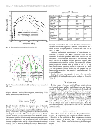
Fig. 4. Configuration of the Butler matrix network with antenna.
TABLE I
PERFORMANCE OF THE BUTLER MATRIX
Fig. 5. Physical description of the SIW cavity filter.
the entire Butler matrix has the insertion loss of about 1.4 dB at
59.5 GHz.
The Butler matrix integrated with the slot antenna array is
simulated and then measured in system in Section V. The return
losses and isolations are greater than 19 dB in the working band.
From the simulated -plane radiation patterns, it can be ob-
served that the main beam directions are at 42 corresponding
to input ports 2 and 3, and 15 to input ports 4 and 1, respec-
tively. The simulated gain is 18 dBi when port 1 or 4 is excited.
2) 60-GHz SIW BandPass Filter: In a typical receiver archi-
tecture, it is necessary to apply a bandpass filter before the LNA.
The 60-GHz SIW filter is naturally chosen for our subsystem de-
sign because it has an excellent performance and also an easy in-
tegration with the Butler matrix. As with the filter design in [31],
a four-order Chebyshev SIW cavity filter is designed, as shown
in Fig. 5. Details of the parameters of the filter are mm,
mm, mm, ,
and . In our measurement, a -band test fixture
and thru-reflect-line (TRL) calibration method are used. Fig. 6
shows simulated and measured frequency responses of the filter.
The insertion loss and return loss in the passband are around
1.2 dB and greater than 15 dB from 58 to 63 GHz, respectively.
3) 60-GHz LNA: In the RF front-end, a three-stage GaAs
monolithic microwave integrated circuit (MMIC) LNA Hittite
HMC-ALH382, which has a high dynamic range and operating
Fig. 6. Simulated and measured frequency responses and group delay of the
SIW bandpass filter.
Fig. 7. Measured frequency responses of the 60-GHz LNA model.
frequency range between 57–65 GHz, is used. This die chip
LNA features 20 dB of small-signal gain, 4 dB of noise figure
(NF), and an output power of 12 dBm at 1-dB compression
from a 2.5-V supply voltage. It is necessary to use a miniature
hybrid microwave integrated circuit (MHMIC) process to fabri-
cate an LNA model with the HMC-ALH382 chip on a ceramic
substrate with 10-mil thickness and dielectric constant .
A CBCPW is used as the transmission line to connect the LNA
chip and other components. Fig. 7 displays measured frequency
responses of the LNA model. The measured gain of the LNA is
about 19 dB at 59.5 GHz.
4) 60-GHz Sub-Harmonically Pumped Mixer: The proto-
type of the sub-harmonically pumped mixer is the same as the
up-converter proposed in [32], except that the SIW filter is re-
placed by a section of SIW in the 60-GHz mixer. The section
of SIW is designed with the cutoff frequency at 50 GHz so high
LO/RF and IF/RF isolations can be obtained. In this design, the
mixer is designed with an LO frequency of 29 GHz and an IF
frequency of 1.5 GHz. The circuit is designed and fabricated
on a Rogers/Duroid 6010 substrate with a dielectric constant
of 10.2 and thickness of 0.254 mm. The Schottky antiparallel](https://image.slidesharecdn.com/40ce1d63-1e79-4c17-ac3f-5e72ae98403a-150814062620-lva1-app6892/85/Low-Cost-60-GHz-Smart-Antenna-Receiver-Sub-System-Based-on-Substrate-Integrated-Waveguide-Technology-4-320.jpg)
![1160 IEEE TRANSACTIONS ON MICROWAVE THEORY AND TECHNIQUES, VOL. 60, NO. 4, APRIL 2012
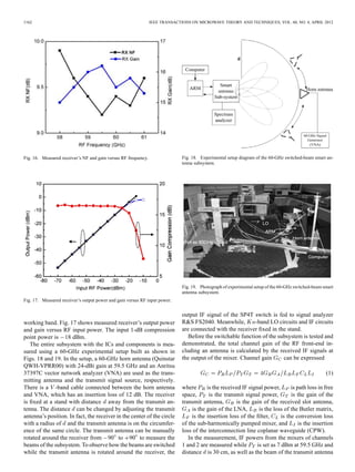
Fig. 8. Measured conversion losses versus RF frequency.
Fig. 9. Basic block diagram of the -band LO source.
diode pair used is MGS802 from Aeroflex/Metalics Inc., Lon-
donderry, NH.
The measured conversion loss will remain around 16 dB
when the LO input power level is larger than 11 dBm, where
the RF signal is fixed at 59.5 GHz with the input power level
of 20 dBm and LO frequency is 29 GHz. Therefore, the
minimized LO input power level of 11.5 dBm is chosen to
pump the diode pair. Fig. 8 shows measured conversion losses
versus the IF frequency when the IF signal is swept from 58.4
to 62 GHz with a constant input power level of 20 dBm
and the LO signal is fixed at the frequency of 29 GHz with
11.5-dBm power level. The measured 1-dB compression power
is 3 dBm.
5) -Band LO Source Model: To drive the 60-GHz sub-
harmonically pumped mixer, a -band LO source model with
a SIW VCO and a SIW frequency tripler is designed. Fig. 9 plots
the basic block diagram of the proposed -band LO source.
The RF power is developed by the SIW VCO presented in our
studies [33]. This VCO can produce the RF signal with an output
power of 6.5–9.8 dBm from 9.36 to 9.81 GHz. As the -band
buffer amplifier, RFMD’s broadband InGaP/GaAs MMIC am-
plifier NBB-310 is used to drive the SIW frequency tripler. At
least an 15-dBm power level can be produced at the output of
the amplifier. Through the SIW frequency tripler, the signal is
converted from 9.36–9.81 to 28.08–29.43 GHz. To meet the
power requirement of the LO of the sub-harmonically pumped
mixer, Hittite’s -band power amplifiers (PAs) HMC566LP4
and HMC499LC4 are cascaded to obtain the power level of
20–22 dBm.
The designed tripler is a balanced passive multiplier uti-
lizing a planar Schottky antiparallel diode pair MGS802 from
Aeroflex/Metalics Inc. A passive multiplier has the advantages
of being wideband and stable due to no dc supply. Using the
Fig. 10. Diagram of the SIW frequency tripler.
Fig. 11. Conversion loss versus input frequency for the designed frequency
tripler.
antiparallel diode pair to build a tripler, the even harmonics are
suppressed inherently. That is, all even harmonics are shorted
by the antiparallel diode pair. Fig. 10 shows the diagram of the
SIW frequency tripler. At the input of the tripler, a
open-circuited stub on the right side of a diode pair is used
to provide a shorted terminal for frequency, where is
the fundamental frequency. A section of SIW with the cutoff
frequency of 25 GHz is fabricated on the left side of the diode
pair to suppress the fundamental and second harmonics and
then provide a good isolation at the output. The circuit is
fabricated on a Rogers/Duroid 6010 substrate with a dielectric
constant of 10.2 and a thickness of 0.254 mm. The -band
frequency tippler exhibits a measured conversion loss of
14.8–16 dB for the input power of 11 dBm over the frequency
band of 27–36 GHz, as shown in Fig. 11. At the output fre-
quency of 29 GHz, the conversion loss is about 15 dB. Fig. 12
displays the measured output power versus the input power of
the frequency tripler at the output frequency of 29 GHz.
Using the circuits described here, the source is constructed as
shown in Fig. 13. Fig. 14 shows the output frequency and power
of the frequency tripler versus the varactor tuning voltage in the
designed SIW VCO. As has been pointed out above, the mixer
needs 11.5-dBm LO power to pump the diode pair. Thus, the
subsystem needs the LO power of at least 17.5 dBm because
there are four mixers in system. It can be seen that the designed
-band source can meet the power requirement for the LO.
IV. IF CIRCUITS BLOCK WITH CONTROL BLOCK
The above section has described the four received 59.5-GHz
RF signals at the four ports of the Butler matrix, which are am-](https://image.slidesharecdn.com/40ce1d63-1e79-4c17-ac3f-5e72ae98403a-150814062620-lva1-app6892/85/Low-Cost-60-GHz-Smart-Antenna-Receiver-Sub-System-Based-on-Substrate-Integrated-Waveguide-Technology-5-320.jpg)
![HE et al.: LOW-COST 60-GHz SMART ANTENNA RECEIVER SUBSYSTEM BASED ON SIW TECHNOLOGY 1161
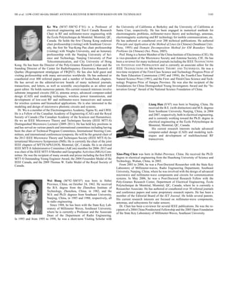
Fig. 12. Output power versus input power at 29 GHz.
Fig. 13. Photograph of the -band source model.
Fig. 14. Output frequency and power of the frequency tripler versus varactor
tuning voltage in VCO.
plified and frequency down-converted to the four 1.5-GHz IF
signals from IF1 to IF4, where IF1–IF 4 mean the four IF signals
from channels 1 to 4, respectively. This following part describes
how to compare the four IF signals and judge which channel re-
ceives the maximum power, and then switch the beam to the
main direction.
The block diagram of the IF circuit, which consists of IF
low-pass filters, amplifiers, couplers, power detector, and dc
Fig. 15. Block diagram of IF circuit with control block.
filter, is shown in Fig. 15. The AVX low-pass filter has an in-
sertion loss of 0.5- and 3-dB bandwidth of 2.6 GHz. After the
AVX low-pass filter, an Infineon silicon–germanium broadband
MMIC amplifier BGA614 is used to amplify the IF signal. The
amplifier has a typical gain of 16 dB and an NF of 2 dB. In
order to generate the four IF signals of comparison, four 10-dB
couplers are used, which were purchased from Johanson Tech-
nology Inc., Camarillo, CA. The four coupling signals are then
introduced to power detector AD8313 from Analog Devices,
Norwood, MA, and the four main IF signals to SP4T switch
AS204 from Skyworks Inc., Woburn, MA, respectively. De-
tector AD8313 has a wide bandwidth of 0.1–2.5 GHz and a high
dynamic range of 70 3.0 dB. The minimum detectable input
signal power is about 75 dBm with output dc voltage of about
0.5 V. The AS204-80 is a high-isolation SP4T field-effect tran-
sistor (FET) integrated circuit (IC) nonreflective switch with a
driver. The insertion loss is 0.5 dB and the isolation is 43 dB at
1.5 GHz. At each IF input port, the minimum IF input power of
65 dBm can be detected with an output dc voltage of 0.53 V.
That is, only a 1.5-GHz IF signal from a mixer with over 65
dBm can be detected to judge which output of the Butler matrix
has the maximum received signal.
Passing through the dc filter, the four detected dc signals
are then converted to digital signals by ADCs and sent into a
[digital signal processing (DSP)] model. In this design, Atmel
AT91SAM7SE512 is used as the DSP unit. AT91SAM7SE512
is an ARM processor that provides integrated ADCs. This ADC
has 10-bit resolution mode, and the conversion results are re-
ported in a common register for all channels, as well as in a
channel-dedicated register. The interval time between two sam-
plings is 1 ms, which is enough for indoor communications be-
cause most people walk at an average speed of 1.2–1.4 m/s.
V. EXPERIMENTS AND RESULTS
Before we test the entire receiver subsystem with a digital
block, one channel of the receiver is measured from RF filter
to IF coupler. Fig. 16 shows receiver’s NF and gain in the](https://image.slidesharecdn.com/40ce1d63-1e79-4c17-ac3f-5e72ae98403a-150814062620-lva1-app6892/85/Low-Cost-60-GHz-Smart-Antenna-Receiver-Sub-System-Based-on-Substrate-Integrated-Waveguide-Technology-6-320.jpg)
![1164 IEEE TRANSACTIONS ON MICROWAVE THEORY AND TECHNIQUES, VOL. 60, NO. 4, APRIL 2012
REFERENCES
[1] “Amendment of parts 2, 15 and 97 of the Commission’s rules to permit
use of radio frequencies above 40 GHz for new radio applications,”
FCC, Washington, DC, 1995.
[2] “FCC 95-499” FCC, Washington, DC, 1995. [Online]. Available:
[Online]. Available: ftp://ftp.fcc.gov/pub/Bureaus/Engineering_Tech-
nology/Orders/1995/fcc95499.txt
[3] “Frequency range 29.7 MHz to 105 GHz and associated European
table of frequency allocations and utilizations,” Eur. Radio Commun.
Commission, Copenhagen, Denmark, 2004. [Online]. Available:
http://www.ero.dk
[4] P. Smulders, “Exploiting the 60 GHz band for local wireless multi-
media access: Prospects and future directions,” IEEE Commun. Mag.,
vol. 40, no. 1, pp. 140–147, Jan. 2002.
[5] B. Bosco, R. Emrick, S. Franson, J. Holmes, and S. Rockwell,
“Emerging commercial applications using the 60 GHz unlicensed
band: Opportunities and challenges,” in Proc. Wireless Microw.
Technol. Conf., Dec. 2006, pp. 1–4.
[6] K. Ohata, K. Maruhashi, M. Ito, S. Kishimoto, K. Ikuina, T.
Hashiguchi, N. Takahashi, and S. Iwanaga, “Wireless 1.25 Gb/s
transceiver modules utilizing multilayer co-fired ceramic technology,”
in IEEE Int. Solid-State Circuits Conf., Feb. 7–9, 2000, vol. 1, pp.
298–468.
[7] B. Bosco, R. Emrick, S. Franson, J. Holmes, and S. Rockwell,
“Emerging commercial applications using the 60 GHz unlicensed
band: Opportunities and challenges,” in Proc. Wireless Microw.
Technol. Conf., Dec. 2006, pp. 1–4.
[8] K. Ohata et al., “Wireless 1.25 Gb/s transceiver modules utilizing mul-
tilayer co-fired ceramic technology,” in IEEE Int. Solid-State Circuits
Conf., Feb. 7–9, 2000, pp. 120–123.
[9] H. Tanaka and T. Ohira, “A single-planar integrated self-heterodyne
receiver with a built-in beam-steerable array antenna for 60-GHz-band
video transmission systems,” in IEEE MTT-S Int. Microw. Symp. Dig.,
Jun. 2004, vol. 2, pp. 735–738.
[10] G. Grosskopf et al., “Maximum directivity beam-former at 60 GHz
with optical feeder,” IEEE Trans. Antennas Propag., vol. 51, no. 11,
pp. 3040–3046, Nov. 2003.
[11] M. Bona, L. Manholm, J. P. Starski, and B. Svensson, “Low-cost com-
pact Butler matrix for a microstrip antenna,” IEEE Trans. Microw.
Theory Tech., vol. 50, no. 9, pp. 2069–2075, Sep. 2002.
[12] G. Tudosie, H. Barth, and R. Vahldieck, “A compact LTCC Butler ma-
trix realization for phased array applications,” in IEEE MTT-S Int. Mi-
crow. Symp. Dig., Jun. 2006, pp. 441–444.
[13] H.-S. Wu, C.-K. C. Tzuang, and R.-B. Wu, “ -band 32-GHz planar
integrated switched-beam smart antenna,” in IEEE MTT-S Int. Microw.
Symp. Dig., Jun. 2005, pp. 565–568.
[14] C.-W. Wang, T.-G. Ma, and C.-F. Yang, “A new planar artificial trans-
mission line and its applications to a miniaturized Butler matrix,” IEEE
Trans. Microw. Theory Tech., vol. 55, no. 12, pp. 2792–2801, Dec.
2007.
[15] K. Wu, D. Deslandes, and Y. Cassivi, “The substrate integrated
circuits—A new concept for high-frequency electronics and op-
toeletronics,” in 6th Int. Telecommun. Modern Satellite, Cable,
Broadcast. Service Conf., Oct. 2003, vol. 1, pp. P-III–P-X.
[16] D. Deslandes and K. Wu, “Integrated microstrip and rectangular wave-
guide in planar form,” IEEE Microw. Wireless Compon. Lett., vol. 11,
no. 2, pp. 68–70, Feb. 2001.
[17] F. F. He, X. P. Chen, K. Wu, and W. Hong, “Electrically tunable
substrate integrated waveguide reflective cavity resonator,” in Proc.
Asia–Pacific Microw. Conf., Dec. 2009, pp. 119–122.
[18] C. L. Zhong, J. Xu, Z. Y. Yu, and Y. Zhu, “ -band substrate inte-
grated waveguide Gunn oscillator,” IEEE Microw. Wireless Compon.
Lett., vol. 18, no. 7, pp. 461–463, Feb. 2008.
[19] L. Yan, W. Hong, G. Hua, J. Chen, K. Wu, and T. J. Cui, “Simulation
and experiment on SIW slot array antennas,” IEEE Microw. Wireless
Compon. Lett., vol. 14, no. 9, pp. 446–448, Sep. 2004.
[20] M. Ohira, A. Miura, and M. Ueba, “60-GHz wideband substrate-inte-
grated-waveguide slot array using closely spaced elements for planar
multisector antenna,” IEEE Trans. Antennas Propag., vol. 58, no. 3,
pp. 993–998, Mar. 2010.
[21] C. J. Chen and T. H. Chu, “Design of a 60-GHz substrate integrated
waveguide Butler matrix—A systematic approach,” IEEE Trans. Mi-
crow. Theory Tech., vol. 58, no. 7, pp. 1724–1733, Jul. 2010.
[22] P. Chen, W. Hong, Z. Kuai, and J. Xu, “A double layer substrate inte-
grated waveguide Blass matrix for beamforming applications,” IEEE
Microw. Wireless Compon. Lett., vol. 19, no. 6, pp. 374–376, Jun. 2009.
[23] J. Xu, Z. N. Chen, X. Qing, and W. Hong, “Bandwidth enhancement
for a 60 GHz substrate integrated waveguide fed cavity array antenna
on LTCC,” IEEE Trans. Antennas Propag., vol. 59, no. 3, pp. 826–832,
Mar. 2011.
[24] X.-P. Chen, K. Wu, L. Han, and F. F. He, “Low-cost high gain planar
antenna array for 60-GHz band applications,” IEEE Trans. Antennas
Propag., vol. 57, no. 1, pp. 64–71, Jan. 2009.
[25] W. Hong, B. Liu, G. Q. Luo, Q. H. Lai, J. F. Xu, Z. C. Hao, F. F. He, and
X. X. Yin, “Integrated microwave and millimetre wave antennas based
on SIW and HMSIW technology,” in Int. Antenna Technol. Workshop:
Small and Smart Antennas Metamater. Appl., Mar. 2007, pp. 69–72.
[26] K. K. Samanta, D. Stephens, and I. D. Robertson, “60 GHz multi-
chip-module receiver with substrate integrated waveguide antenna and
filter,” Electron. Lett., vol. 42, no. 12, pp. 701–702, 2006.
[27] B. Pan, Y. Li, G. E. Ponchak, M. M. Tentzeris, J. Papapolymerou,
and J. , “A low-loss substrate-independent approach for 60-GHz
transceiver front-end integration using micromachining technologies,”
IEEE Trans. Microw. Theory Tech., vol. 56, no. 12, pp. 2779–2788,
Dec. 2008.
[28] S. Cheng, H. Yousef, and H. Kratz, “79 GHz slot antennas based on
substrate integrated waveguides (SIW) in a flexible printed circuit
board,” IEEE Trans. Antennas Propag., vol. 57, no. 1, pp. 64–71, Jan.
2009.
[29] S. Yamamoto, J. Hirokawa, and M. Ando, “A half-sized post-wall
short-slot directional coupler with hollow rectangular holes in a dielec-
tric substrate,” IEICE Trans. Electron., vol. 88, no. 7, pp. 1387–1394,
Jul. 2005.
[30] Y. J. Cheng, W. Hong, and K. Wu, “Broadband self-compensating
phase shifter combining delay line and equal-length unequal-width
phaser,” IEEE Trans. Microw. Theory Tech., vol. 58, no. 1, pp.
2792–2801, Jan. 2010.
[31] X. P. Chen, K. Wu, and D. Drolet, “Substrate integrated waveguide
filter with improved stopband performance for satellite ground
terminal,” IEEE Trans. Microw. Theory Tech., vol. 57, no. 3, pp.
674–683, Mar. 2009.
[32] F. F. He, W. Hong, K. Wu, J. X. Chen, H. B. Zhu, and H. J. Tang,
“Substrate integrated waveguide sub-harmonically pumped up-con-
verter antenna for spatial power combining,” in IET Proc. Microw.,
Antennas Propag., 2009, vol. 8, no. 3, pp. 1172–1178.
[33] F. F. He, K. Wu, W. Hong, X. P. Chen, and L. Han, “A low phase noise
VCO using a novel tunable substrate integrated waveguide resonator,”
IEEE Trans. Microw. Theory Tech., vol. 58, no. 12, pp. 3452–3458,
Dec. 2010.
[34] M. Tahesh, J. Chen, C. Marcu, L. Kong, S. Kang, A. M. Niknejad,
and E. Alon, “A 65 nm CMOS 4-element sub-34 Mw/element 60 GHz
phased-array transceiver,” IEEE J. Solid-State Circuits, vol. 46, no. 12,
pp. 3018–3012, Dec. 2011.
[35] E. Cohen, C. Jakobson, S. Ravid, and D. Ritter, “A thirty two element
phased-array transceiver at 60 GHz with RF-IF conversion block in
90 nm flip chip CMOS process,” in IEEE Radio Freq. Integr. Circuits
Symp. Dig., May 2010, pp. 457–460.
[36] S. K. Reynolds, A. S. Natarajan, M.-D. Tsai, S. Nicolson, J.-H. C. Zhan,
D. Liu, D. G. Kam, O. Huang, A. Valdes-Garcia, and B. A. Floyd, “A
16-element phased-array receiver IC for 60-GHz communications in
SiGe BiCMOS,” in IEEE Radio Freq. Integr. Circuits Symp. Dig., May
2010, pp. 461–464.
Fan Fan He was born in Nanjing, China. He
received M.S. degree in mec-electrical engineering
from Xidian University, Xi’an, China, in 2005, and
is currently working toward the Ph.D. degree in
electrical engineering at both Southeast University,
Nanjing, China, and the École Polytechnique de
Montréal, Montréal, QC, Canada.
He is currently an exchange student with the École
Polytechnique de Montréal. His current research in-
terests include advanced microwave and millimeter-
wave components and systems.](https://image.slidesharecdn.com/40ce1d63-1e79-4c17-ac3f-5e72ae98403a-150814062620-lva1-app6892/85/Low-Cost-60-GHz-Smart-Antenna-Receiver-Sub-System-Based-on-Substrate-Integrated-Waveguide-Technology-9-320.jpg)


![[IJCT-V3I2P20] Authors: Gidijala Sai Kumar,Gadiraju Mounika , Dusi Leela Ran...](https://cdn.slidesharecdn.com/ss_thumbnails/ijct-v3i2p20-160609061626-thumbnail.jpg?width=640&height=640&fit=bounds)