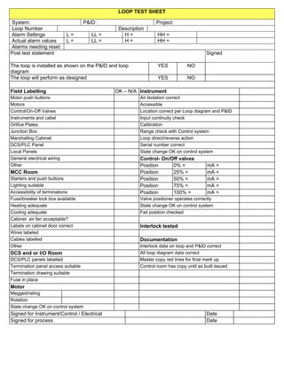
LOOP TEST SHEET
System: P&ID: Project:
Loop Number Description
Alarm Settings L = LL = H = HH =
Actual alarm values L = LL = H = HH =
Alarms needing reset
Post test statement Signed
The loop is installed as shown on the P&ID and loop
diagram
YES NO
The loop will perform as designed YES NO
Field Labelling OK – N/A Instrument
Motor push buttons Air Isolation correct
Motors Accessible
Control/On-Off Valves Location correct per Loop diagram and P&ID
Instruments and cabel Input continuity check
Orifice Plates Calibration
Junction Box Range check with Control system
Marshalling Cabinet Loop direct/reverse action
DCS/PLC Panel Serial number correct
Local Panels State change OK on control system
General electrical wiring Control- On/Off valves
Other Position 0% = mA =
MCC Room Position 25% = mA =
Starters and push buttons Position 50% = mA =
Lighting suitable Position 75% = mA =
Accessibility of terminations Position 100% = mA =
Fuse/breaker lock box available Valve positioner operates correctly
Heating adequate State change OK on control system
Cooling adequate Fail position checked
Cabinet air fan acceptable?
Labels on cabinet door correct Interlock tested
Wires labeled
Cables labelled Documentation
Other Interlock data on loop and P&ID correct
DCS and or I/O Room All loop diagram data correct
DCS/PLC panels labelled Master copy red lines for final mark up
Termination panel access suitable Control room has copy until as built issued
Termination drawing suitable
Fuse in place
Motor
Megged/rating
Rotation
State change OK on control system
Signed for Instrument/Control / Electrical Date
Signed for process Date

Loop test sheet

  • 1.
    LOOP TEST SHEET System:P&ID: Project: Loop Number Description Alarm Settings L = LL = H = HH = Actual alarm values L = LL = H = HH = Alarms needing reset Post test statement Signed The loop is installed as shown on the P&ID and loop diagram YES NO The loop will perform as designed YES NO Field Labelling OK – N/A Instrument Motor push buttons Air Isolation correct Motors Accessible Control/On-Off Valves Location correct per Loop diagram and P&ID Instruments and cabel Input continuity check Orifice Plates Calibration Junction Box Range check with Control system Marshalling Cabinet Loop direct/reverse action DCS/PLC Panel Serial number correct Local Panels State change OK on control system General electrical wiring Control- On/Off valves Other Position 0% = mA = MCC Room Position 25% = mA = Starters and push buttons Position 50% = mA = Lighting suitable Position 75% = mA = Accessibility of terminations Position 100% = mA = Fuse/breaker lock box available Valve positioner operates correctly Heating adequate State change OK on control system Cooling adequate Fail position checked Cabinet air fan acceptable? Labels on cabinet door correct Interlock tested Wires labeled Cables labelled Documentation Other Interlock data on loop and P&ID correct DCS and or I/O Room All loop diagram data correct DCS/PLC panels labelled Master copy red lines for final mark up Termination panel access suitable Control room has copy until as built issued Termination drawing suitable Fuse in place Motor Megged/rating Rotation State change OK on control system Signed for Instrument/Control / Electrical Date Signed for process Date