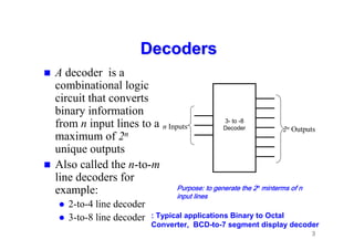
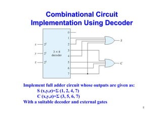
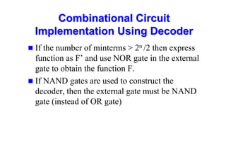
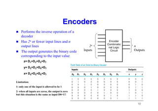
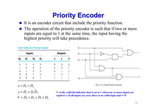
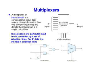
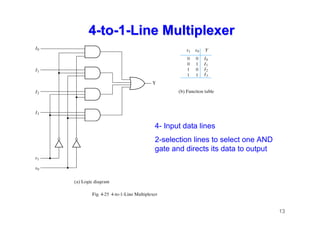
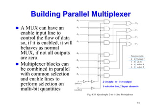
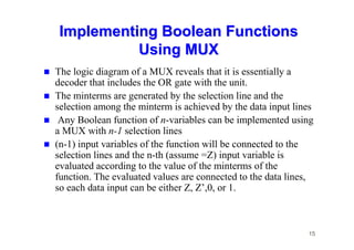
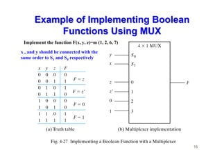
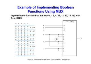
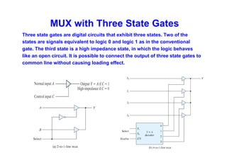
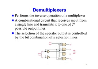
1
Combinational Logic
Combinational Logic
Implementation Using
Implementation Using Decoders,
Decoders,
Encoders & Multiplexers
EEE 122/A Digital Logic Circuits
2
Combinational Circuits
 The outputs are a function of the present set of
inputs only
 The inside of a combinational circuit is made of
logic gates
 Combinational logic circuits are important
components of digital systems
 Each output can be thought of as a function of
all the inputs – if there are m outputs and n
inputs then there are m Boolean functions, one
describing each output
3
Decoders
Decoders
 A decoder is a
combinational logic
circuit that converts
binary information
from n input lines to a
maximum of 2n
unique outputs
 Also called the n-to-m
line decoders for
example:
 2-to-4 line decoder
 3-to-8 line decoder
3- to -8
Decoder
n Inputs 2n Outputs
Purpose: to generate the 2
Purpose: to generate the 2n
n
n
n minterms of n
minterms of n
minterms of n
minterms of n
input lines
input lines
input lines
input lines
: Typical applications Binary to Octal
Converter, BCD-to-7 segment display decoder
4
Inner Structure of
Inner Structure of
Decoder
Decoder
Generally: The inner
structure of Decoders is
composed of an array of
AND or NAND gates
that generate the
required minterm.
5
NAND Decoder with Enable Line
One or more input control line may be used to control the operation of decoder
Decoders with enable lines can work as de-multiplexer where data is provided
through the enable lines and the input variables are used to select specific
output channel
6
Decoder Expansion
Decoder Expansion
 Smaller Decoders with enable
lines can be used to build bigger
Decoders.
 In the figure two 3-8 decoders
are used to build a 4-16
decoder.
 Input w is used as enable line,
when w=0, the upper decoder is
enabled so, outputs D0 to D7 are
available, while D8- to- D15 are
all zeros. When w=1 the
operation is reversed and the
lower decoder is enabled while
all the outputs of the upper
encoder are zeros
4x16 Decoder constructed with
two 3x8 Decoders
7
Combinational Circuit
Implementation Using Decoder
 Since decoders produce 2n minterms of n- input variables, an external
OR gates can be used to form a logical functionin SOP form
 To implement a given function with decoder and external gates:
- express the function as canonical SOP
- select decoder that has no of inputs equat to the number of input
variables in the given functions,
- select the proper external gate
 E.g. Implement full adder circuit whose outputs are given as:
S (x,y,z)=Σ (1, 2, 4, 7)
C (x,y,z)=Σ (3, 5, 6, 7)
With a suitable decoder and external gates
8
Combinational Circuit
Implementation Using Decoder
Implement full adder circuit whose outputs are given as:
S (x,y,z)=Σ (1, 2, 4, 7)
C (x,y,z)=Σ (3, 5, 6, 7)
With a suitable decoder and external gates
Combinational Circuit
Implementation Using Decoder
 If the number of minterms  2n /2 then express
function as F’ and use NOR gate in the external
gate to obtain the function F.
 If NAND gates are used to construct the
decoder, then the external gate must be NAND
gate (instead of OR gate)
10
Encoders
Encoders
 Performs the inverse operation of a
decoder
 Has 2n or fewer input lines and n
output lines
 The output generates the binary code
corresponding to the input value
Encoder
Combinatio
nal Logic
Circuit
n
Outputs
2n
Inputs
z= D1+D3+D5+D7
y= D2+D3+D6+D7
x= D4+D5+D6+D7
Limitation:
1- only one of the input is allowed to be 1
2- when all inputs are zeros, the output is zero
but this situation is the same as input D0=1!!
11
Priority
Priority Encoder
Encoder
 It is an encoder circuit that include the priority function.
 The operation of the priority encoder is such that if two or more
inputs are equal to 1 at the same time, the input having the
highest priority will take precedence.
0
1
2
3
2
1
3
2
3
D
D
D
D
V
D
D
D
y
D
D
x
+
+
+
=
+
=
+
=
V: is the valid bit indicator that is set to 1 when one or more inputs are
equal to 1. If all inputs are zero, there is no valid input and V=0
12
Multiplexers
Multiplexers
 A multiplexer or
Data Selector is a
combinational circuit that
selects binary information from
one of many input lines and
directs the information to a
single output line
MULTIPLEXER
Combinational
Logic Circuit
1
Output
2n
Inputs
n Selection Lines
The selection of a particular input
line is controlled by a set of
selection lines. For 2n data line
we have n selection lines
13
4
4-
-to
to-
-1
1-
-Line Multiplexer
Line Multiplexer
4- Input data lines
2-selection lines to select one AND
gate and directs its data to output
14
Building
Building Parallel
Parallel M
Multiplexer
ultiplexer
 A MUX can have an
enable input line to
control the flow of data
so, if it is enabled, it will
behaves as normal
MUX, if not all outputs
are zero.
 Multiplexer blocks can
be combined in parallel
with common selection
and enable lines to
perform selection on
multi-bit quantities
2 set data- to- 1 set output
1 selection line, 2 input channels
15
Implementing Boolean Functions
Using MUX
Using MUX
 The logic diagram of a MUX reveals that it is essentially a
decoder that includes the OR gate with the unit.
 The minterms are generated by the selection line and the
selection among the minterm is achieved by the data input lines
 Any Boolean function of n-variables can be implemented using
a MUX with n-1 selection lines
 (n-1) input variables of the function will be connected to the
selection lines and the n-th (assume =Z) input variable is
evaluated according to the value of the minterms of the
function. The evaluated values are connected to the data lines,
so each data input can be either Z, Z’,0, or 1.
16
Example of Implementing Boolean
Functions Using MUX
Functions Using MUX
Implement the function F(x, y, z)=m (1, 2, 6, 7)
x , and y should be connected with the
same order to S1 and S0 respectively
17
Example of Implementing Boolean
Functions Using MUX
Functions Using MUX
Implement the function F(A, B,C,D)=m(1, 3, 4, 11, 12, 13, 14, 15) with
8-to-1 MUX
MUX with Three State Gates
Three state gates are digital circuits that exhibit three states. Two of the
states are signals equivalent to logic 0 and logic 1 as in the conventional
gate. The third state is a high impedance state, in which the logic behaves
like an open circuit. It is possible to connect the output of three state gates to
common line without causing loading effect.
19
Demultiplexers
Demultiplexers
 Performs the inverse operation of a multiplexer
 A combinational circuit that receives input from
a single line and transmits it to one of 2n
possible output lines
 The selection of the specific output is controlled
by the bit combination of n selection lines

EEE122CombinationalLogicdsddChapter4.pdf

  • 1.
    1 Combinational Logic Combinational Logic ImplementationUsing Implementation Using Decoders, Decoders, Encoders & Multiplexers Encoders & Multiplexers EEE 122/A Digital Logic Circuits
  • 2.
    2 Combinational Circuits Combinational Circuits The outputs are a function of the present set of inputs only The inside of a combinational circuit is made of logic gates Combinational logic circuits are important components of digital systems Each output can be thought of as a function of all the inputs – if there are m outputs and n inputs then there are m Boolean functions, one describing each output
  • 3.
    3 Decoders Decoders A decoderis a combinational logic circuit that converts binary information from n input lines to a maximum of 2n unique outputs Also called the n-to-m line decoders for example: 2-to-4 line decoder 3-to-8 line decoder 3- to -8 Decoder n Inputs 2n Outputs Purpose: to generate the 2 Purpose: to generate the 2 Purpose: to generate the 2 Purpose: to generate the 2n n n n minterms of n minterms of n minterms of n minterms of n input lines input lines input lines input lines : Typical applications Binary to Octal Converter, BCD-to-7 segment display decoder
  • 4.
    4 Inner Structure of InnerStructure of Decoder Decoder Generally: The inner structure of Decoders is composed of an array of AND or NAND gates that generate the required minterm.
  • 5.
    5 NAND Decoder withEnable Line NAND Decoder with Enable Line One or more input control line may be used to control the operation of decoder Decoders with enable lines can work as de-multiplexer where data is provided through the enable lines and the input variables are used to select specific output channel
  • 6.
    6 Decoder Expansion Decoder Expansion Smaller Decoders with enable lines can be used to build bigger Decoders. In the figure two 3-8 decoders are used to build a 4-16 decoder. Input w is used as enable line, when w=0, the upper decoder is enabled so, outputs D0 to D7 are available, while D8- to- D15 are all zeros. When w=1 the operation is reversed and the lower decoder is enabled while all the outputs of the upper encoder are zeros 4x16 Decoder constructed with two 3x8 Decoders
  • 7.
    7 Combinational Circuit Combinational Circuit ImplementationUsing Decoder Implementation Using Decoder Since decoders produce 2n minterms of n- input variables, an external OR gates can be used to form a logical functionin SOP form To implement a given function with decoder and external gates: - express the function as canonical SOP - select decoder that has no of inputs equat to the number of input variables in the given functions, - select the proper external gate E.g. Implement full adder circuit whose outputs are given as: S (x,y,z)=Σ (1, 2, 4, 7) C (x,y,z)=Σ (3, 5, 6, 7) With a suitable decoder and external gates
  • 8.
    8 Combinational Circuit Combinational Circuit ImplementationUsing Decoder Implementation Using Decoder Implement full adder circuit whose outputs are given as: S (x,y,z)=Σ (1, 2, 4, 7) C (x,y,z)=Σ (3, 5, 6, 7) With a suitable decoder and external gates
  • 9.
    Combinational Circuit Combinational Circuit ImplementationUsing Decoder Implementation Using Decoder If the number of minterms 2n /2 then express function as F’ and use NOR gate in the external gate to obtain the function F. If NAND gates are used to construct the decoder, then the external gate must be NAND gate (instead of OR gate)
  • 10.
    10 Encoders Encoders Performs theinverse operation of a decoder Has 2n or fewer input lines and n output lines The output generates the binary code corresponding to the input value Encoder Combinatio nal Logic Circuit n Outputs 2n Inputs z= D1+D3+D5+D7 y= D2+D3+D6+D7 x= D4+D5+D6+D7 Limitation: 1- only one of the input is allowed to be 1 2- when all inputs are zeros, the output is zero but this situation is the same as input D0=1!!
  • 11.
    11 Priority Priority Encoder Encoder Itis an encoder circuit that include the priority function. The operation of the priority encoder is such that if two or more inputs are equal to 1 at the same time, the input having the highest priority will take precedence. 0 1 2 3 2 1 3 2 3 D D D D V D D D y D D x + + + = + = + = V: is the valid bit indicator that is set to 1 when one or more inputs are equal to 1. If all inputs are zero, there is no valid input and V=0
  • 12.
    12 Multiplexers Multiplexers A multiplexeror Data Selector is a combinational circuit that selects binary information from one of many input lines and directs the information to a single output line MULTIPLEXER Combinational Logic Circuit 1 Output 2n Inputs n Selection Lines The selection of a particular input line is controlled by a set of selection lines. For 2n data line we have n selection lines
  • 13.
    13 4 4- -to to- -1 1- -Line Multiplexer Line Multiplexer 4-Input data lines 2-selection lines to select one AND gate and directs its data to output
  • 14.
    14 Building Building Parallel Parallel M Multiplexer ultiplexer A MUX can have an enable input line to control the flow of data so, if it is enabled, it will behaves as normal MUX, if not all outputs are zero. Multiplexer blocks can be combined in parallel with common selection and enable lines to perform selection on multi-bit quantities 2 set data- to- 1 set output 1 selection line, 2 input channels
  • 15.
    15 Implementing Boolean Functions ImplementingBoolean Functions Using MUX Using MUX The logic diagram of a MUX reveals that it is essentially a decoder that includes the OR gate with the unit. The minterms are generated by the selection line and the selection among the minterm is achieved by the data input lines Any Boolean function of n-variables can be implemented using a MUX with n-1 selection lines (n-1) input variables of the function will be connected to the selection lines and the n-th (assume =Z) input variable is evaluated according to the value of the minterms of the function. The evaluated values are connected to the data lines, so each data input can be either Z, Z’,0, or 1.
  • 16.
    16 Example of ImplementingBoolean Example of Implementing Boolean Functions Using MUX Functions Using MUX Implement the function F(x, y, z)=m (1, 2, 6, 7) x , and y should be connected with the same order to S1 and S0 respectively
  • 17.
    17 Example of ImplementingBoolean Example of Implementing Boolean Functions Using MUX Functions Using MUX Implement the function F(A, B,C,D)=m(1, 3, 4, 11, 12, 13, 14, 15) with 8-to-1 MUX
  • 18.
    MUX with ThreeState Gates Three state gates are digital circuits that exhibit three states. Two of the states are signals equivalent to logic 0 and logic 1 as in the conventional gate. The third state is a high impedance state, in which the logic behaves like an open circuit. It is possible to connect the output of three state gates to common line without causing loading effect.
  • 19.
    19 Demultiplexers Demultiplexers Performs theinverse operation of a multiplexer A combinational circuit that receives input from a single line and transmits it to one of 2n possible output lines The selection of the specific output is controlled by the bit combination of n selection lines