Download as PDF, PPTX
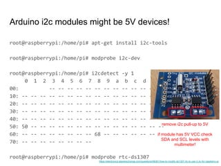
![dpavlin@cubieboard:~/linux-gpio-pinout$ sudo ./gpio.pl 2>/dev/null | egrep '(^#|[)'
## U14 (Next to SATA connector)
### SPI0
48 PI13 2 0 1 [spi0 MISO] 47 PI11 2 0 1 [spi0 CLK]
46 PI12 2 0 1 [spi0 MOSI] 45 PI10 2 0 1 [spi0 CS]
### LCD
32 PD25 0 0 1 0 31 PB2 2 0 1 [pwm pwm]
## U15 (Between Ethernet port and USB ports)
### CSI1/TS
5 PG0 0 0 1 0 6 PB18 2 0 1 [i2c1 SCK]
7 PB19 2 0 1 [i2c1 SDA] 8 PG3 0 1 1 1 "E-mail" in hi [gpio-3-buttons gpio_in]
9 PG2 0 0 1 0 10 PG1 0 1 1 1 "Connect" in hi [gpio-3-buttons gpio_in]
11 PG4 0 0 1 0 12 PG5 0 1 1 1 "Print" in hi [gpio-3-buttons gpio_in]
13 PG6 4 0 1 [ttyS3 TX uart3] 14 PG7 4 0 1 [ttyS3 RX uart3]
17 PG10 4 0 1 [ttyS4 TX uart4] 18 PG11 4 0 1 [ttyS4 RX uart4]
### Analog SDIO3
### CSI0/TS
## DEBUG serial (middle of board)
4 PB22 2 0 1 [ttyS0 TX uart0]
3 PB23 2 1 1 [ttyS0 RX uart0]
and again with horizontal or vertical flip depending on board orientation (top,
bottom, rotation...)
output friendly to grep in terminal with [kernel info]](https://image.slidesharecdn.com/linuxsensordevice-treeshelliot-180806081341/85/Linux-sensor-device-tree-shell-IoT-6-320.jpg)
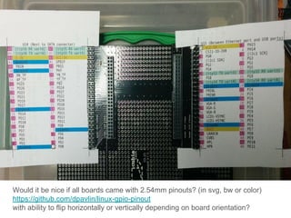
![i2c debugging - alternative to logic analyzer
dpavlin@cubieboard2:~/linux-gpio-pinout$ cat i2c-tracing.sh
#!/bin/sh
if [ -z "$1" ] ; then
echo "Usage: $0 0|1 - disable/enable i2c tracking"
exit 1
fi
echo $1 > /sys/kernel/debug/tracing/events/i2c/enable
# echo adapter_nr==1 >/sys/kernel/debug/tracing/events/i2c/filter
cat /sys/kernel/debug/tracing/trace](https://image.slidesharecdn.com/linuxsensordevice-treeshelliot-180806081341/85/Linux-sensor-device-tree-shell-IoT-10-320.jpg)

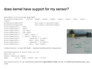
![Does my pin has irq support? /sys/kernel/debug/
root@rpi:~# grep Hardware /proc/cpuinfo
Hardware : BCM2835
root@rpi:~# grep -r irq /sys/kernel/debug/pinctrl/ | head
/sys/kernel/debug/pinctrl/20200000.gpio/pins:pin 0 (gpio0) function alt0 in hi; irq 160 (none)
/sys/kernel/debug/pinctrl/20200000.gpio/pins:pin 1 (gpio1) function alt0 in hi; irq 161 (none)
/sys/kernel/debug/pinctrl/20200000.gpio/pins:pin 2 (gpio2) function alt0 in hi; irq 162 (none)
/sys/kernel/debug/pinctrl/20200000.gpio/pins:pin 3 (gpio3) function alt0 in hi; irq 163 (none)
/sys/kernel/debug/pinctrl/20200000.gpio/pins:pin 4 (gpio4) function gpio_in in hi; irq 164 (none)
/sys/kernel/debug/pinctrl/20200000.gpio/pins:pin 5 (gpio5) function gpio_out in lo; irq 165 (none)
/sys/kernel/debug/pinctrl/20200000.gpio/pins:pin 6 (gpio6) function gpio_out in hi; irq 166 (none)
/sys/kernel/debug/pinctrl/20200000.gpio/pins:pin 7 (gpio7) function gpio_in in hi; irq 167 (none)
/sys/kernel/debug/pinctrl/20200000.gpio/pins:pin 8 (gpio8) function gpio_in in hi; irq 168 (none)
/sys/kernel/debug/pinctrl/20200000.gpio/pins:pin 9 (gpio9) function gpio_in in lo; irq 169 (none)
root@cubieboard:~# grep Hardware /proc/cpuinfo
Hardware : Allwinner sun4i/sun5i Families
root@cubieboard:~# grep -r irq /sys/kernel/debug/pinctrl/
/sys/kernel/debug/pinctrl/1c20800.pinctrl/pinmux-functions:function: irq, groups = [ PH0 PH1 PH2 PH3 PH4 PH5 PH6 PH7
PH8 PH9 PH10 PH11 PH12 PH13 PH14 PH15 PH16 PH17 PH18 PH19 PH20 PH21 PI10 PI11 PI12 PI13 PI14 PI15 PI16 PI17 PI18 PI19 ]
Different on different hardware, but still kernel knows!](https://image.slidesharecdn.com/linuxsensordevice-treeshelliot-180806081341/85/Linux-sensor-device-tree-shell-IoT-16-320.jpg)
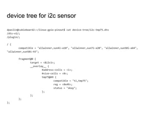
![Test new input events using evtest
root@cubieboard:~# evtest
No device specified, trying to scan all of /dev/input/event*
Available devices:
/dev/input/event0: axp20x-pek
/dev/input/event1: gpio-3-buttons
/dev/input/event2: sunxi-ir
Select the device event number [0-2]: 1
Input driver version is 1.0.1
Input device ID: bus 0x19 vendor 0x1 product 0x1 version 0x100
Input device name: "gpio-3-buttons"
Supported events:
Event type 0 (EV_SYN)
Event type 1 (EV_KEY)
Event code 210 (KEY_PRINT)
Event code 215 (KEY_EMAIL)
Event code 218 (KEY_CONNECT)
Key repeat handling:
Repeat type 20 (EV_REP)
Repeat code 0 (REP_DELAY)
Value 250
Repeat code 1 (REP_PERIOD)
Value 33](https://image.slidesharecdn.com/linuxsensordevice-treeshelliot-180806081341/85/Linux-sensor-device-tree-shell-IoT-17-320.jpg)

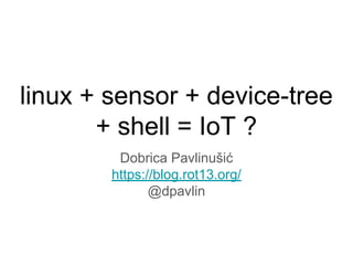
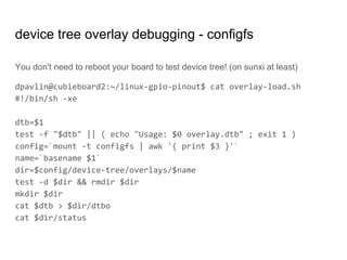
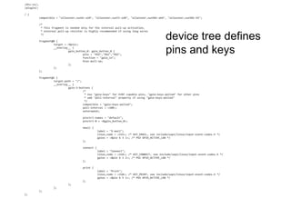
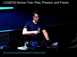
![this board from old thinkpad dock adds leds with
cpu and mmc activity and buttons to arm sbc
first step is to test all pins with transistor tester
and figure out connections from board layout
good reason to horde old parts :-)
[and number pins, compare with notes]](https://image.slidesharecdn.com/linuxsensordevice-treeshelliot-180806081341/85/Linux-sensor-device-tree-shell-IoT-21-320.jpg)
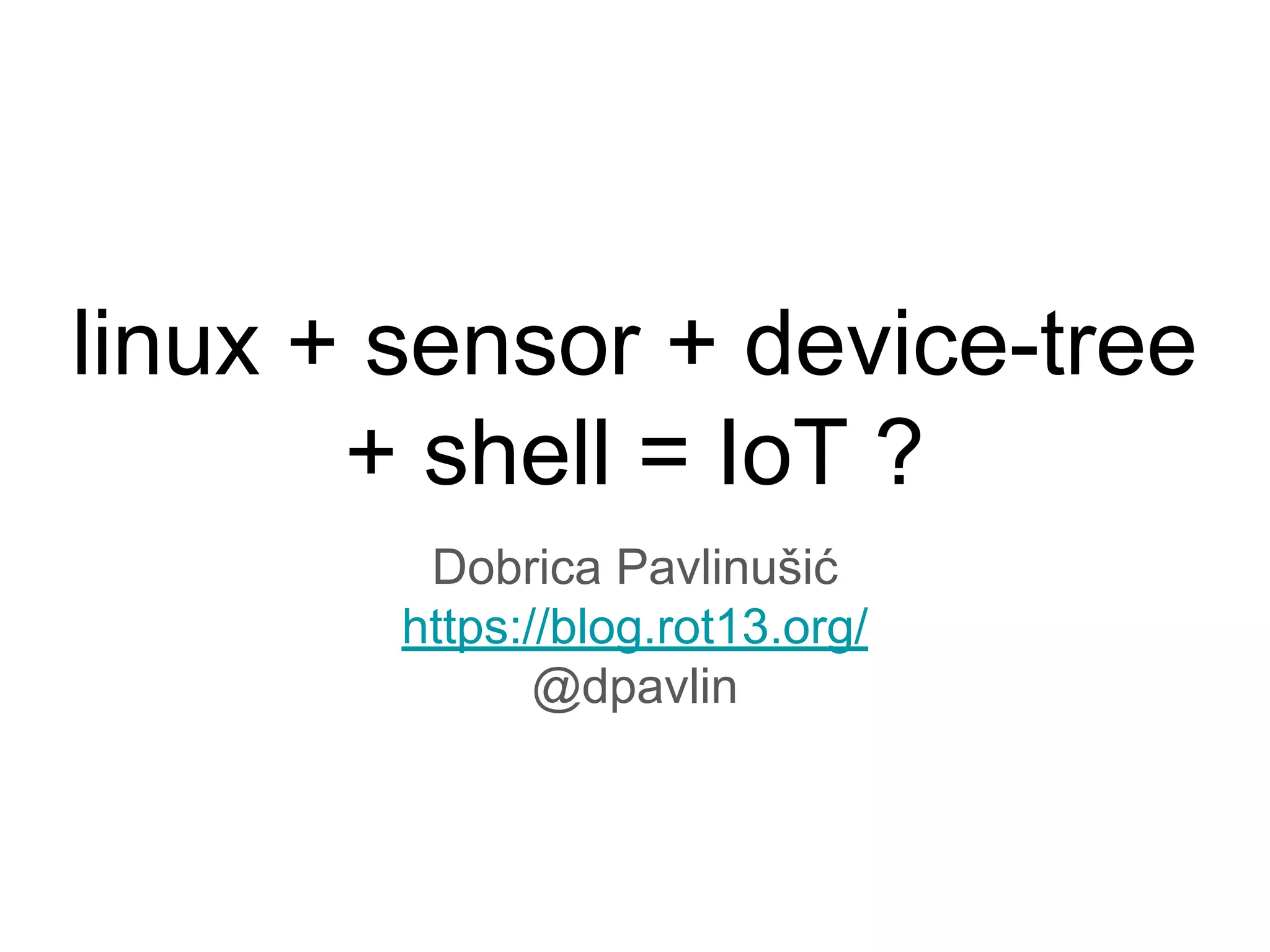
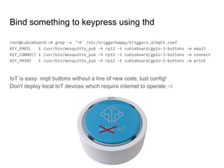
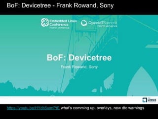
![root@ntpi:~# dmesg | grep rotary
[ 10.370238] rotary-encoder rotary@0: gray
[ 10.393505] input: rotary@0 as /devices/platform/rotary@0/input/input0
root@ntpi:~# grep rotary /boot/config.txt
dtoverlay=rotary-encoder,rollover,steps=20
root@ntpi:~# evtest /dev/input/event0
Input device name: "rotary@0"
Supported events:
Event type 0 (EV_SYN)
Event type 3 (EV_ABS)
Event code 0 (ABS_X)
Value 0
Min 0
Max 20
Flat 1
Properties:
Testing ... (interrupt to exit)
Event: time 1523107078.786053, type 3 (EV_ABS), code 0 (ABS_X), value 1
Event: time 1523107078.786053, -------------- SYN_REPORT ------------
Event: time 1523107080.280269, type 3 (EV_ABS), code 0 (ABS_X), value 2
Event: time 1523107080.280269, -------------- SYN_REPORT ------------
rotary encoder from /boot/overlays/README](https://image.slidesharecdn.com/linuxsensordevice-treeshelliot-180806081341/85/Linux-sensor-device-tree-shell-IoT-22-320.jpg)
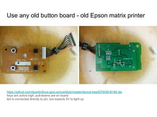
![OpenTechLab[002] Testing the Linux Kernel driver for the Lattice iCE40 FPGA
https://opentechlab.org.uk/videos:002:notes good device-tree introduction](https://image.slidesharecdn.com/linuxsensordevice-treeshelliot-180806081341/85/Linux-sensor-device-tree-shell-IoT-28-320.jpg)

The document discusses using Linux with ARM boards and various sensors through device trees and shell commands for Internet of Things (IoT) applications. It emphasizes that users do not need to learn new programming languages but can utilize existing kernel drivers to interact with GPIO and I2C sensors. The talk targets hobbyists with ARM boards who want to integrate cheap sensors from platforms such as eBay or AliExpress without extensive hardware modifications or programming.


![[5]投影片 futurewad樹莓派研習會 141218](https://cdn.slidesharecdn.com/ss_thumbnails/5futurewad141218-141219162301-conversion-gate02-thumbnail.jpg?width=640&height=640&fit=bounds)


![谷歌留痕技术教程[ 𝙩𝙤𝙥 𝟮𝟯𝟯. 𝙘 𝙤𝙢 ]](https://cdn.slidesharecdn.com/ss_thumbnails/top233-260130173900-2eb784f9-thumbnail.jpg?width=640&height=640&fit=bounds)

![20260201 [FOSDEM] gomodjail - library sandboxing for Go modules.pdf](https://cdn.slidesharecdn.com/ss_thumbnails/20260201fosdemgomodjail-librarysandboxingforgomodules-260201225659-76609ec4-thumbnail.jpg?width=640&height=640&fit=bounds)


