Download to read offline

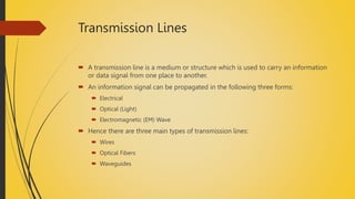
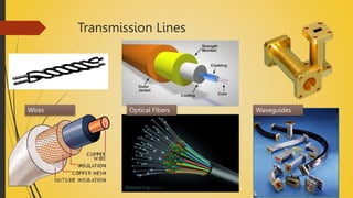

The document discusses transmission lines, which are used to carry information signals in electrical, optical, or electromagnetic forms. It covers the primary line constants such as resistance, inductance, capacitance, and conductance, and introduces secondary line constants including attenuation, phase shift, and propagation coefficients. Additionally, the attenuation coefficient is defined as the measure of signal strength reduction along a transmission line.


