The document provides an overview of light microscopes, including their history, components, and types. It discusses:
- The development of simple microscopes in the 1500s and the invention of the compound microscope in the 1590s, improving magnification. Key figures who advanced microscopy include Galileo, Leeuwenhoek, Hooke, and Janssen.
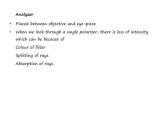
- The main components of light microscopes, including illumination sources, objectives, eyepieces, and condensers used to provide uniform lighting.
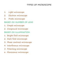
- Different types of microscopes classified by illumination method (brightfield, darkfield, etc.), number of lenses, or use of electromagnetic fields/electron beams.
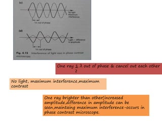
- Optical properties important to microscopy