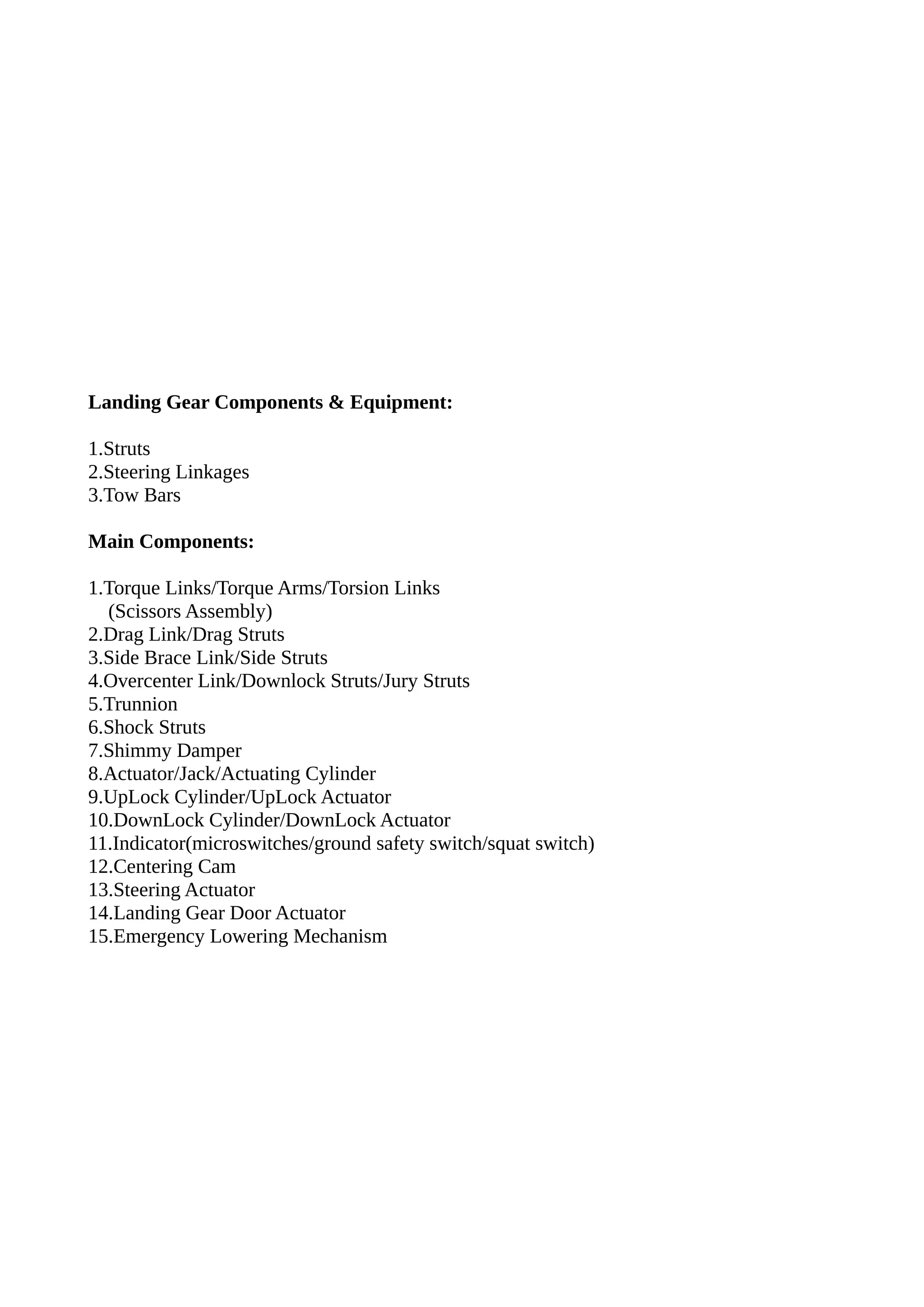
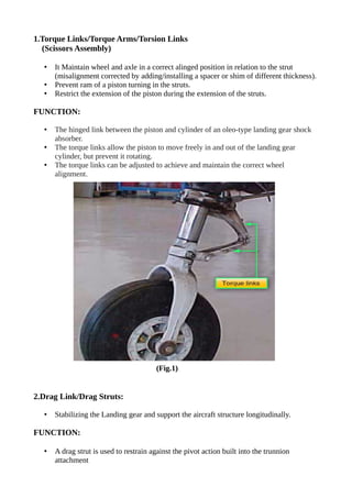
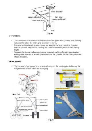
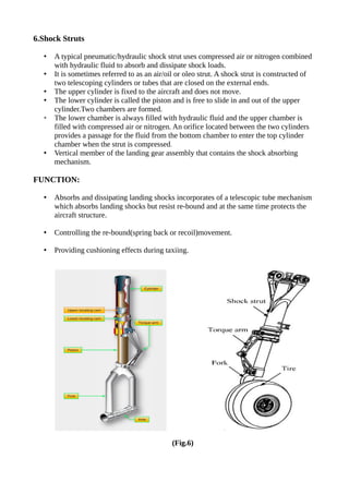
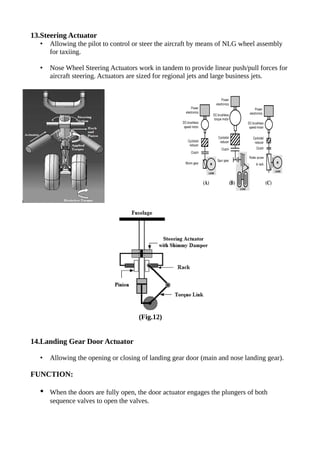
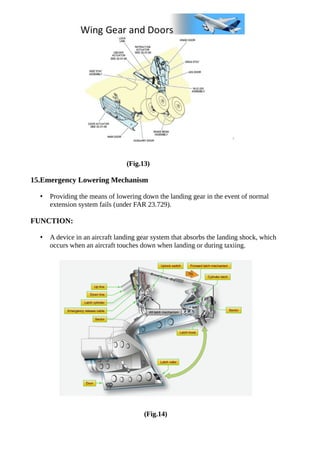
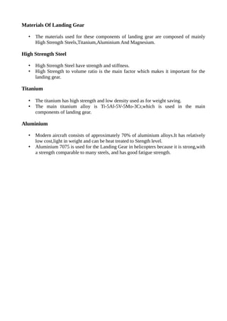
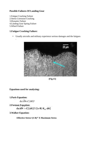
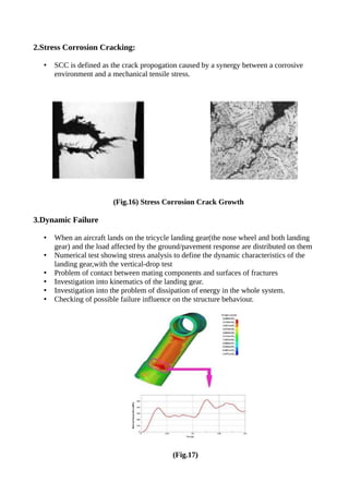
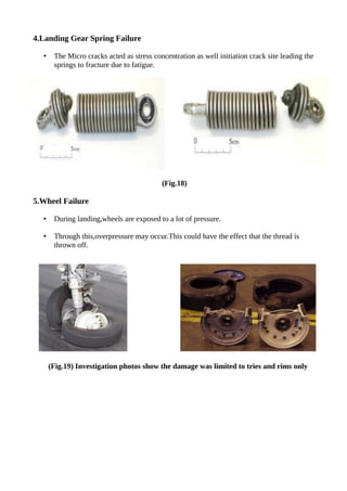
The document summarizes the key components of aircraft landing gear systems. It describes 15 main components including torque links, drag links, shock struts, actuators, and indicators. It explains the purpose and function of each component. Common failure modes like fatigue cracking and stress corrosion cracking are also summarized. The document provides diagrams to illustrate important landing gear concepts.
Abstract:
Landing gear is one of the critical subsystems of an aircraft. The need to design landing gear with minimum weight, minimum volume, high performance, improved life and reduced life cycle cost have posed many challenges to landing gear designers and practitioners. Further it is essential to reduce the landing gear design and development cycle time while meeting all the regulatory and safety requirements. Many technologies have been developed over the years to meet these challenges in design and development of landing gear. This paper presents a perspective on various stages of landing gear design and development, current technology landscape and how these technologies are helping us to meet the challenges involved in the development of landing gear and how they are going to evolve in future.
NAME : S. Srinivasa Phani Kumar
Branch : MECHANICAL
College : SWARNANDHRA COLLEGE OF ENGINEERING & TECHNOLOGY
Airplane (fixed wing aircraft) configuration and various parts | Flight Mecha...Age of Aerospace
For Video Lecture of this presentation: https://youtu.be/uD_qWvTZEhY
The topics covered in this session are, Airplane (fixed wing aircraft) configurations and various parts of airplane. A detailed list of airplane configuration is discussed with general insight about airplane parts.
Attention! "Gate Aerospace Engineering aspirants", A virtual guide for gate aerospace engineering is provided in "Age of Aerospace" blog for helping you meticulously prepare for gate examination. Respective notes of individual subjects are provided as 'Embedded Google Docs' which are frequently updated. This comprehensive guide is intended to efficiently serve as an extensive collection of online resources for "GATE Aerospace Engineering" which can be accessed free of cost. Use the following link to access the study material
https://ageofaerospace.blogspot.com/p/gate-aerospace.html
THIS PRESENTATION TAKES OVERVIEW OF AIRCRAFT CABIN PRESSURIZATION SYSTEM. IN THIS I EXPLAINED BASIC SYSTEM USED FOR PRESSURIZATION , AND HOW THIS SYSTEM IS SAFE, PRECISE. AND HOW AIR IS KEPT HEALTHY.
Nomenclature and classification of controls in an airplane (slide # 3-4).
Which are the aerodynamic forces acting on airplane (slide # 5).
Working principle of an airplane (slide # 6).
How an airplane flies (basic motions of an airplane) (slide # 7).
How controls play their roles in these motions (slide # 8-22).
Simulate a flight in Cessna Skyhawk (slide # 23-28).
References and Questions & answers (slide # 30).
Emergency ejection system in military aircraft reportLahiru Dilshan
Safety is a major concern in the aircraft industry both in commercial and military services. In the fighter jets, there are several unique mechanisms used other than the commercial airliner. Pilots in the fighter jects can abandon the ship in case of an emergency but the other types of aircraft cannot use that kind of mechanism because the passengers are boarded.
Water billing management system project report.pdfKamal Acharya
Our project entitled “Water Billing Management System” aims is to generate Water bill with all the charges and penalty. Manual system that is employed is extremely laborious and quite inadequate. It only makes the process more difficult and hard.
The aim of our project is to develop a system that is meant to partially computerize the work performed in the Water Board like generating monthly Water bill, record of consuming unit of water, store record of the customer and previous unpaid record.
We used HTML/PHP as front end and MYSQL as back end for developing our project. HTML is primarily a visual design environment. We can create a android application by designing the form and that make up the user interface. Adding android application code to the form and the objects such as buttons and text boxes on them and adding any required support code in additional modular.
MySQL is free open source database that facilitates the effective management of the databases by connecting them to the software. It is a stable ,reliable and the powerful solution with the advanced features and advantages which are as follows: Data Security.MySQL is free open source database that facilitates the effective management of the databases by connecting them to the software.
Understanding Inductive Bias in Machine LearningSUTEJAS
This presentation explores the concept of inductive bias in machine learning. It explains how algorithms come with built-in assumptions and preferences that guide the learning process. You'll learn about the different types of inductive bias and how they can impact the performance and generalizability of machine learning models.
The presentation also covers the positive and negative aspects of inductive bias, along with strategies for mitigating potential drawbacks. We'll explore examples of how bias manifests in algorithms like neural networks and decision trees.
By understanding inductive bias, you can gain valuable insights into how machine learning models work and make informed decisions when building and deploying them.
Literature Review Basics and Understanding Reference Management.pptxDr Ramhari Poudyal
Three-day training on academic research focuses on analytical tools at United Technical College, supported by the University Grant Commission, Nepal. 24-26 May 2024
Using recycled concrete aggregates (RCA) for pavements is crucial to achieving sustainability. Implementing RCA for new pavement can minimize carbon footprint, conserve natural resources, reduce harmful emissions, and lower life cycle costs. Compared to natural aggregate (NA), RCA pavement has fewer comprehensive studies and sustainability assessments.
HEAP SORT ILLUSTRATED WITH HEAPIFY, BUILD HEAP FOR DYNAMIC ARRAYS.
Heap sort is a comparison-based sorting technique based on Binary Heap data structure. It is similar to the selection sort where we first find the minimum element and place the minimum element at the beginning. Repeat the same process for the remaining elements.
NUMERICAL SIMULATIONS OF HEAT AND MASS TRANSFER IN CONDENSING HEAT EXCHANGERS...ssuser7dcef0
Power plants release a large amount of water vapor into the
atmosphere through the stack. The flue gas can be a potential
source for obtaining much needed cooling water for a power
plant. If a power plant could recover and reuse a portion of this
moisture, it could reduce its total cooling water intake
requirement. One of the most practical way to recover water
from flue gas is to use a condensing heat exchanger. The power
plant could also recover latent heat due to condensation as well
as sensible heat due to lowering the flue gas exit temperature.
Additionally, harmful acids released from the stack can be
reduced in a condensing heat exchanger by acid condensation. reduced in a condensing heat exchanger by acid condensation.
Condensation of vapors in flue gas is a complicated
phenomenon since heat and mass transfer of water vapor and
various acids simultaneously occur in the presence of noncondensable
gases such as nitrogen and oxygen. Design of a
condenser depends on the knowledge and understanding of the
heat and mass transfer processes. A computer program for
numerical simulations of water (H2O) and sulfuric acid (H2SO4)
condensation in a flue gas condensing heat exchanger was
developed using MATLAB. Governing equations based on
mass and energy balances for the system were derived to
predict variables such as flue gas exit temperature, cooling
water outlet temperature, mole fraction and condensation rates
of water and sulfuric acid vapors. The equations were solved
using an iterative solution technique with calculations of heat
and mass transfer coefficients and physical properties.
2. 1.Torque Links/Torque Arms/Torsion Links
(Scissors Assembly)
• It Maintain wheel and axle in a correct alinged position in relation to the strut
(misalignment corrected by adding/installing a spacer or shim of different thickness).
• Prevent ram of a piston turning in the struts.
• Restrict the extension of the piston during the extension of the struts.
FUNCTION:
• The hinged link between the piston and cylinder of an oleo-type landing gear shock
absorber.
• The torque links allow the piston to move freely in and out of the landing gear
cylinder, but prevent it rotating.
• The torque links can be adjusted to achieve and maintain the correct wheel
alignment.
(Fig.1)
2.Drag Link/Drag Struts:
• Stabilizing the Landing gear and support the aircraft structure longitudinally.
FUNCTION:
• A drag strut is used to restrain against the pivot action built into the trunnion
attachment
3. (Fig.2)
3.Side Brace Link/Side Struts:
• Stabilizing the Landing Gear and support the aircraft laterally
(Fig.3)
4.Overcenter Link/Downlock Struts/Jury Struts:
• Holds the drag link and the side brace in the ‘DOWN’ and ‘LOCKED’ position by
applying pressure to the center pivot joint in a drag or side brace link.
• Operates hydraulically by bungee cylinder or mechanically by bungee springs.
FUNCTION:
• The side brace assembly includes a jury strutvwhich functions to lock the side brace
assembly with the landing gear in the extended position.
4. (Fig.4)
5.Trunnion:
• The trunnion is a fixed structural extension of the upper strut cylinder with bearing
surfaces that allow the entire gear assembly to move.
• It is attached to aircraft structure in such a way that the gear can pivot from the
vertical position required for landing and taxi to the stowed position used during
flight.
• Supported at its end by bearing/bushing assemblies,which allow the gear to pivot
during retraction and extension (the struts form the cylinder for the Oleo pneumatic
shock absorber).
FUNCTION:
• The purpose of a trunnion is to structurally support the landing gear in bearing the
weight of the aircraft when it is not flying.
(Fig.5)
5. 6.Shock Struts
• A typical pneumatic/hydraulic shock strut uses compressed air or nitrogen combined
with hydraulic fluid to absorb and dissipate shock loads.
• It is sometimes referred to as an air/oil or oleo strut. A shock strut is constructed of
two telescoping cylinders or tubes that are closed on the external ends.
• The upper cylinder is fixed to the aircraft and does not move.
• The lower cylinder is called the piston and is free to slide in and out of the upper
cylinder.Two chambers are formed.
• The lower chamber is always filled with hydraulic fluid and the upper chamber is
filled with compressed air or nitrogen. An orifice located between the two cylinders
provides a passage for the fluid from the bottom chamber to enter the top cylinder
chamber when the strut is compressed.
• Vertical member of the landing gear assembly that contains the shock absorbing
mechanism.
FUNCTION:
• Absorbs and dissipating landing shocks incorporates of a telescopic tube mechanism
which absorbs landing shocks but resist re-bound and at the same time protects the
aircraft structure.
• Controlling the re-bound(spring back or recoil)movement.
• Providing cushioning effects during taxiing.
(Fig.6)
6. 7.Shimmy Damper
• A shimmy damper uses a cylinder filled with hydraulic fluid or a rubber/lubricant
combination to prevent rapid movement of the nosewheel, while not interfering with
slower operations.
• Hydraulic snubbing unit that reduces the tendency of the nose or tail wheel oscillate
from side to side (rapid oscillation).
FUNCTION:
• A shimmy damper uses a cylinder filled with hydraulic fluid or a rubber/lubricant
combination to prevent rapid movement of the nosewheel, while not interfering with
slower operations.
• It turns the airplane, and the fluid squirts from one end of the cylinder to the other. At
higher speeds, the fluid can’t get through as fast as the nosewheel wants to shimmy,
and the nosewheel is stabilized, preventing shaking.
(Fig.7)
8.Actuator/Jack/Actuating Cylinder
• Landing Gear Retraction Actuators are designed to provide retraction and extension
forces while maintaining light weight and reliability.
• Raise and lowering the landing gear.May also used as a Downlock
mechanism(continous application of pressure).
• Retraction actuators are manufactured from complete hog outs or finish machined
from forgings to a one piece body. Housings are commonly made out of stainless
steel for strength and anti-corrosive properties.
7. • High strength and wear resistant materials are utilized for the piston, end gland, and
bearings to ensure longevity and reliable service without the need for overhauls or
scheduled maintenance.
FUNCTION:
• The landing gear is rotated about a pivot by an extend/retract actuator.
• To retract the landing gear, an unlock actuator pulls the lock-stay from over-center,
which enables the extend/retract actuator to retract the landing gear to the stowed
position. Both the extend/retract and unlock actuators are typically hydraulically
powered.
(Fig.8)
9.UpLock Cylinder/UpLock Actuator
• Locking the landing gear in ‘UP’ and ‘LOCK’ position
10.DownLock Cylinder/DownLock Actuator
• Locking the landing gear in ‘DOWN’ and ‘LOCK’ position
(Fig.9)
8. 11.Indicator(microswitches/ground safety switch/squat switch)
• Means of providing cockpit indication with regards to the landing gear position,either
‘UP’ and ‘LOCKED’,’DOWN’ and ‘Locked’ or in transition and ‘NOT LOCKED’.
• A landing gear squat switch, or safety switch, is found on most aircraft.
• This is a switch positioned to open and close depending on the extension or
compression of the main landing gear strut.
• The squat switch is wired into any number of system operating circuits. One circuit
prevents the gear from being retracted while the aircraft is on the ground.
• There are different ways to achieve this lock-out. A solenoid that extends a shaft to
physically disable the gear position selector is one such method found on many
aircraft.
FUNCTION:
(Squat Switch)
• The squat switch is essentially a sensor that senses if the weight of the aircraft is
resting on the gear.The squat switch is wired into any number of system operating
circuits. One circuit prevents the gear from being retracted while the aircraft is on the
ground.
(Ground Safety Switch)
• A switch in the landing gear that prevents the inadvertent retraction of landing gear
on the ground. This switch usually is located in the port landing gear.
9. (Fig.10)
12.Centering Cam
• Aligning the nose wheel before retracted to ‘UP’ and back to its wheel well
compartment
• A cam in the nose-gear shock strut that causes the piston to center when the strut
fully extends. When the aircraft takes off and the strut extends, the wheel is
straightened in its fore-and-aft position so it can be retracted into the wheel well.
FUNCTION:
• The centering cam forces the nosewheel straight back with the strut before it is
retracted into the nose wheel well.
(Fig.11)
10. 13.Steering Actuator
• Allowing the pilot to control or steer the aircraft by means of NLG wheel assembly
for taxiing.
• Nose Wheel Steering Actuators work in tandem to provide linear push/pull forces for
aircraft steering. Actuators are sized for regional jets and large business jets.
(Fig.12)
14.Landing Gear Door Actuator
• Allowing the opening or closing of landing gear door (main and nose landing gear).
FUNCTION:
• When the doors are fully open, the door actuator engages the plungers of both
sequence valves to open the valves.
11. (Fig.13)
15.Emergency Lowering Mechanism
• Providing the means of lowering down the landing gear in the event of normal
extension system fails (under FAR 23.729).
FUNCTION:
• A device in an aircraft landing gear system that absorbs the landing shock, which
occurs when an aircraft touches down when landing or during taxiing.
(Fig.14)
12. Materials Of Landing Gear
• The materials used for these components of landing gear are composed of mainly
High Strength Steels,Titanium,Aluminium And Magnesium.
High Strength Steel
• High Strength Steel have strength and stiffness.
• High Strength to volume ratio is the main factor which makes it important for the
landing gear.
Titanium
• The titanium has high strength and low density used as for weight saving.
• The main titanium alloy is Ti-5Al-5V-5Mo-3Cr,which is used in the main
components of landing gear.
Aluminium
• Modern aircraft consists of approximately 70% of aluminium alloys.It has relatively
low cost,light in weight and can be heat treated to Stength level.
• Aluminium 7075 is used for the Landing Gear in helicopters because it is strong,with
a strength comparable to many steels, and has good fatigue strength.
13. Possible Failures Of Landing Gear
1.Fatigue Cracking Failure
2.Stress Corrosion Cracking
3.Dynamic Failure
4.Landing Gear Spring Failure
5.Wheel Failure
1.Fatigue Cracking Failure:
• Usually aircrafts and military experience serious damages and the fatigues
.
(Fig.15)
Equations used for analyzing:
1.Paris Equation:
2.Forman Equation:
3.Walker Equation:
Effective Stress=(1-R)m
X Maximum Stress
14. 2.Stress Corrosion Cracking:
• SCC is defined as the crack propogation caused by a synergy between a corrosive
environment and a mechanical tensile stress.
(Fig.16) Stress Corrosion Crack Growth
3.Dynamic Failure
• When an aircraft lands on the tricycle landing gear(the nose wheel and both landing
gear) and the load affected by the ground/pavement response are distributed on them
• Numerical test showing stress analysis to define the dynamic characteristics of the
landing gear,with the vertical-drop test
• Problem of contact between mating components and surfaces of fractures
• Investigation into kinematics of the landing gear.
• Investigation into the problem of dissipation of energy in the whole system.
• Checking of possible failure influence on the structure behaviour.
(Fig.17)
15. 4.Landing Gear Spring Failure
• The Micro cracks acted as stress concentration as well initiation crack site leading the
springs to fracture due to fatigue.
(Fig.18)
5.Wheel Failure
• During landing,wheels are exposed to a lot of pressure.
• Through this,overpressure may occur.This could have the effect that the thread is
thrown off.
(Fig.19) Investigation photos show the damage was limited to tries and rims only