Download as PDF, PPTX


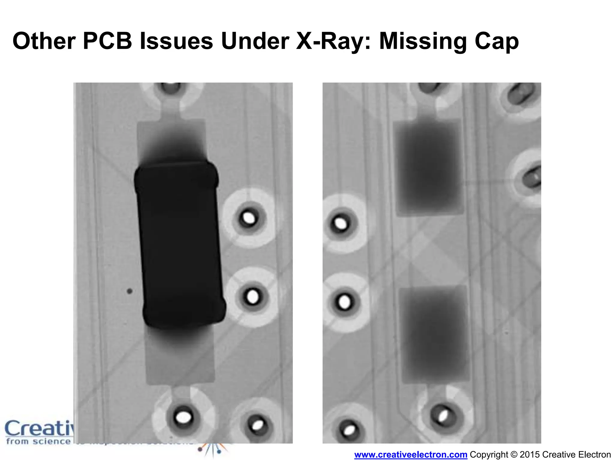


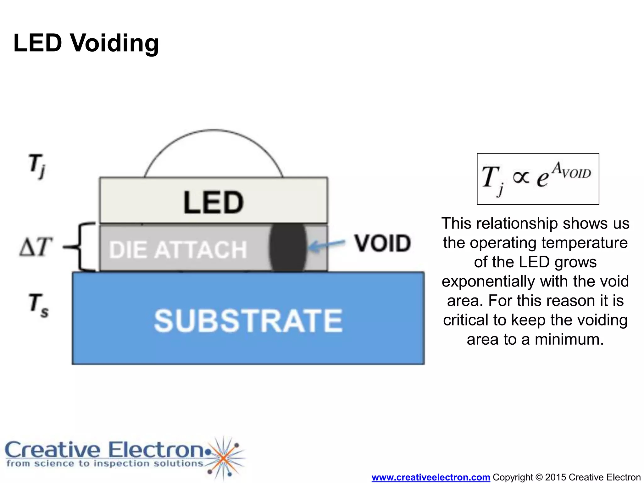
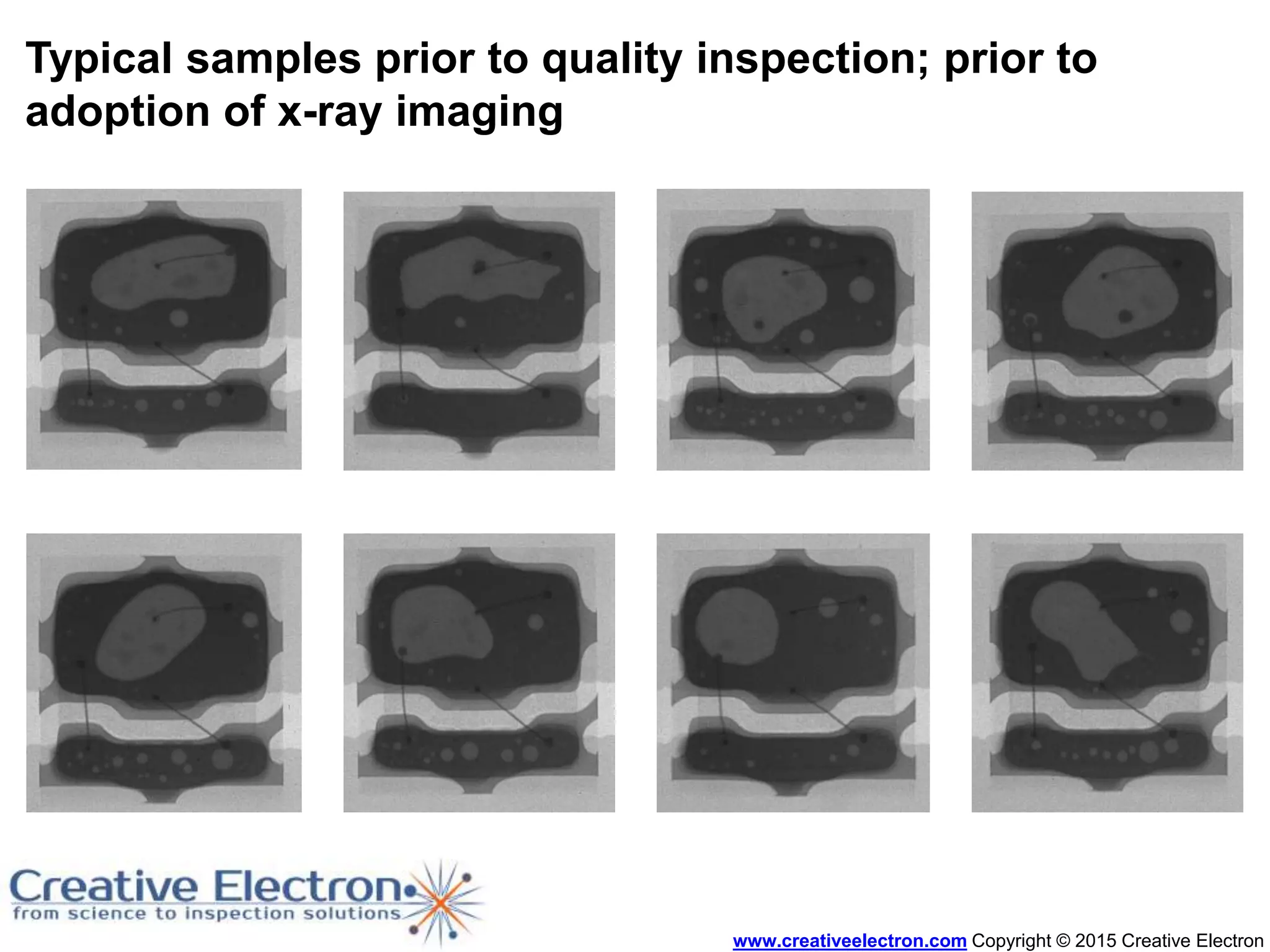
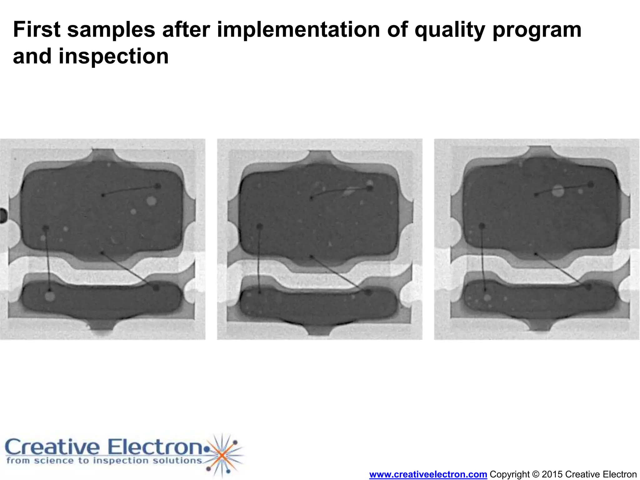


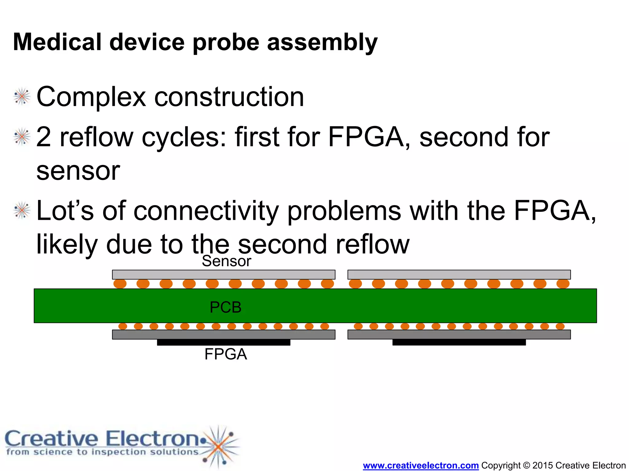


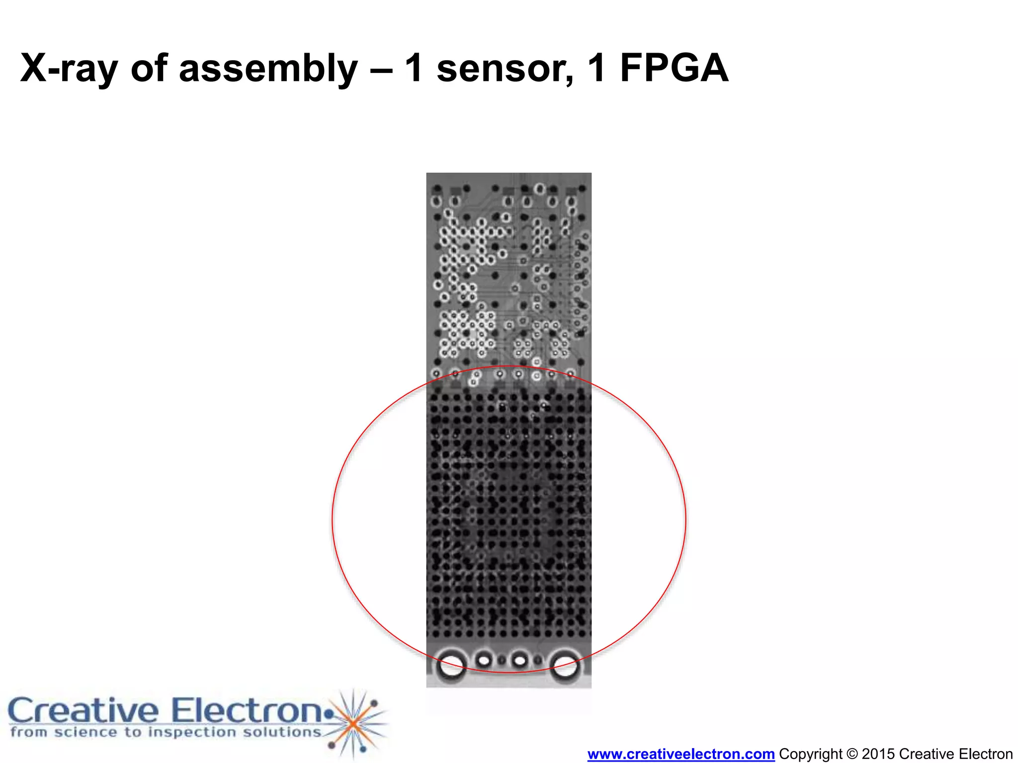
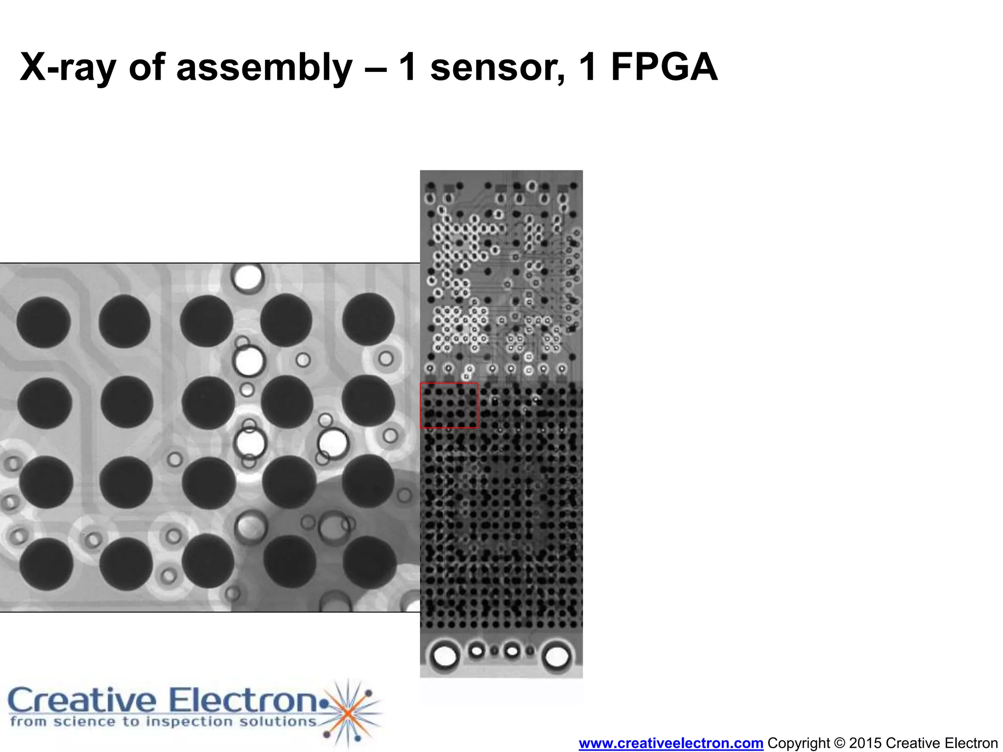

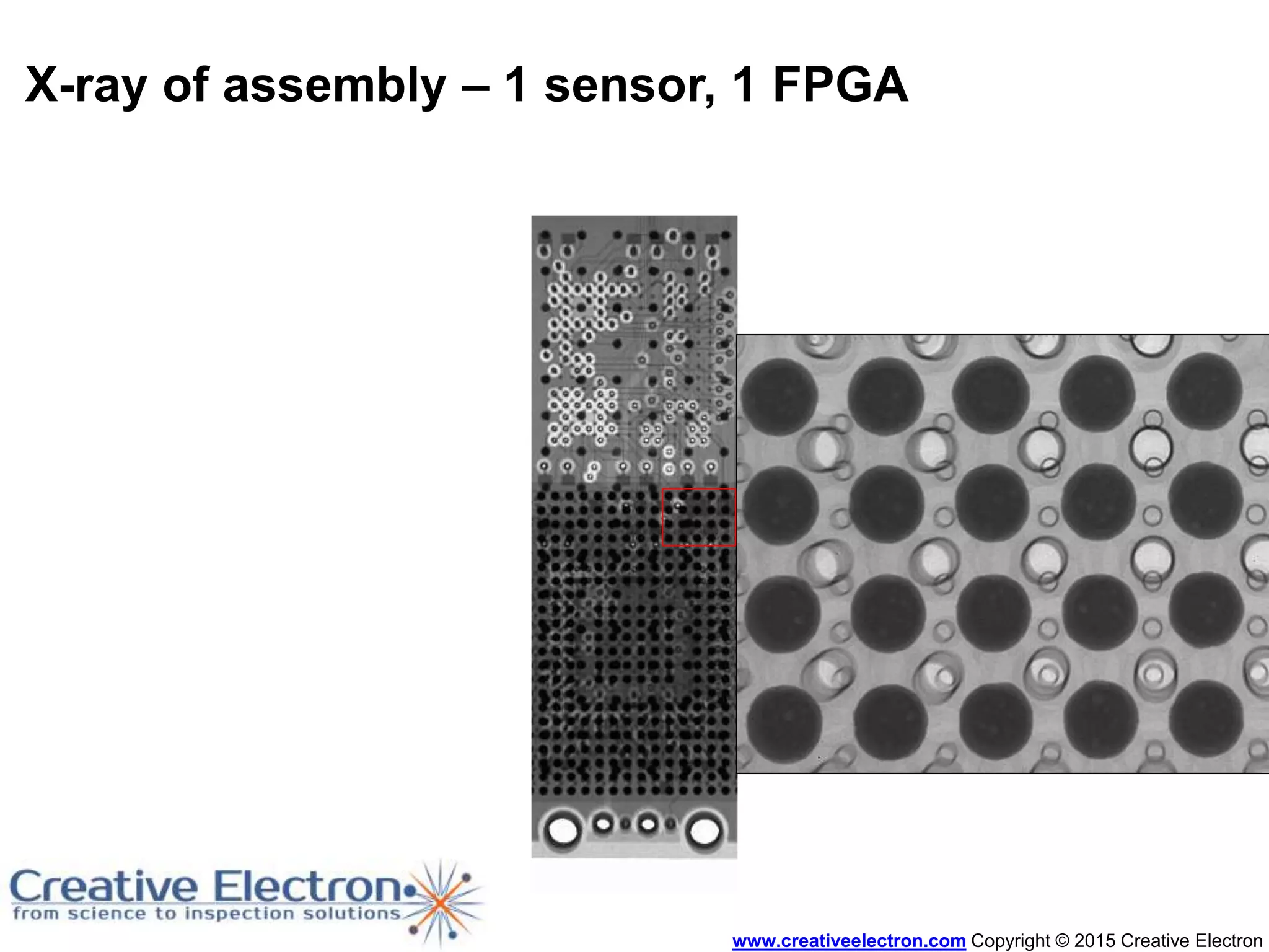


The document discusses the advantages of x-ray inspection in SMT quality assurance, detailing technology, defect origins, and case studies from various manufacturing processes. It highlights the importance of x-ray imaging in diagnosing defects such as solder joint issues and component placement problems, as well as its role in statistical process control. Additionally, it emphasizes the improvements in assembly quality achieved through effective x-ray inspection and proper manufacturing parameters.


