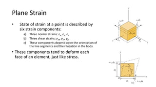
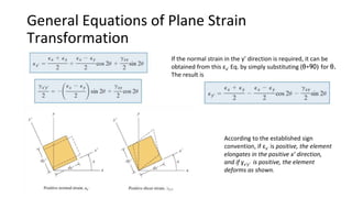
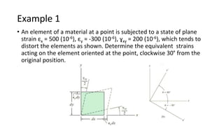
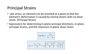
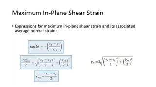
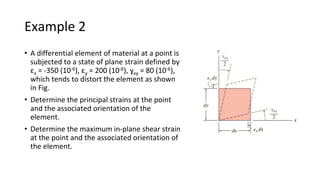
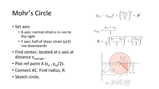
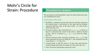
Strain
Transformation
Complex stresses
developed within this
airplane wing are analyzed
from strain gauge data.
1
Plane Strain
• State of strain at a point is described by
six strain components:
a) Three normal strains: εx, εy, εz
b) Three shear strains: γxy, γxz, γyz
c) These components depend upon the orientation of
the line segments and their location in the body
• These components tend to deform each
face of an element, just like stress.
2
General Equations of Plane Strain
Transformation
According to the established sign
convention, if εx’ is positive, the element
elongates in the positive x’ direction,
and if ɣx’y’ is positive, the element
deforms as shown.
If the normal strain in the y’ direction is required, it can be
obtained from this εx’ Eq. by simply substituting (θ+90) for θ.
The result is
Example 1
• An element of a material at a point is subjected to a state of plane
strain εx = 500 (10-6), εy = -300 (10-6), ɣxy = 200 (10-6), which tends to
distort the elements as shown. Determine the equivalent strains
acting on the element oriented at the point, clockwise 30° from the
original position.
Principal Strains
• Like stress, an element can be oriented at a point so that the
element’s deformation is caused by normal strains with no shear
strain. (Principal Strain)
• Expressions for determining in-plane principal directions, in-plane
principal strains, and the maximum in-plane shear strain:
Maximum In-Plane Shear Strain
• Expressions for maximum in-plane shear strain and its associated
average normal strain:
Example 2
• A differential element of material at a point is
subjected to a state of plane strain defined by
εx = -350 (10-6), εy = 200 (10-6), ɣxy = 80 (10-6),
which tends to distort the element as shown
in Fig.
• Determine the principal strains at the point
and the associated orientation of the
element.
• Determine the maximum in-plane shear strain
at the point and the associated orientation of
the element.
Mohr’s Circle
• Set axis:
• X-axis: normal strain ε is +ve to
the right
• Y axis: half of shear strain (γ/2)
+ve downwards
• Find center, located at ε axis at
distance εaverage .
• Plot ref point A (εx , γxy/2).
• Connect AC. Find radius, R.
• Sketch circle.
Mohr’s Circle for
Strain: Procedure
Example 3: Mohr’s Circle for Plane Strain
• The state of plane strain at a point is represented by the components εx =
250 (10-6), εy = -150 (10-6), and ɣxy = 120 (10-6).
• Determine the principal strains and the orientation of the element.
• Determine the maximum in-plane shear strains and the orientation of an
element.
Example 4
• The state of plane strain at a point is represented on an element
having components εx = -300µ , εy = -100µ , and ɣxy = 100µ . Determine
the state of strain on an element oriented 20° clockwise from this
reported position.

LECTURE 4 W5 Strain Transformation.pptx

  • 1.
    Strain Transformation Complex stresses developed withinthis airplane wing are analyzed from strain gauge data. 1
  • 2.
    Plane Strain • Stateof strain at a point is described by six strain components: a) Three normal strains: εx, εy, εz b) Three shear strains: γxy, γxz, γyz c) These components depend upon the orientation of the line segments and their location in the body • These components tend to deform each face of an element, just like stress. 2
  • 3.
    General Equations ofPlane Strain Transformation According to the established sign convention, if εx’ is positive, the element elongates in the positive x’ direction, and if ɣx’y’ is positive, the element deforms as shown. If the normal strain in the y’ direction is required, it can be obtained from this εx’ Eq. by simply substituting (θ+90) for θ. The result is
  • 4.
    Example 1 • Anelement of a material at a point is subjected to a state of plane strain εx = 500 (10-6), εy = -300 (10-6), ɣxy = 200 (10-6), which tends to distort the elements as shown. Determine the equivalent strains acting on the element oriented at the point, clockwise 30° from the original position.
  • 5.
    Principal Strains • Likestress, an element can be oriented at a point so that the element’s deformation is caused by normal strains with no shear strain. (Principal Strain) • Expressions for determining in-plane principal directions, in-plane principal strains, and the maximum in-plane shear strain:
  • 6.
    Maximum In-Plane ShearStrain • Expressions for maximum in-plane shear strain and its associated average normal strain:
  • 7.
    Example 2 • Adifferential element of material at a point is subjected to a state of plane strain defined by εx = -350 (10-6), εy = 200 (10-6), ɣxy = 80 (10-6), which tends to distort the element as shown in Fig. • Determine the principal strains at the point and the associated orientation of the element. • Determine the maximum in-plane shear strain at the point and the associated orientation of the element.
  • 8.
    Mohr’s Circle • Setaxis: • X-axis: normal strain ε is +ve to the right • Y axis: half of shear strain (γ/2) +ve downwards • Find center, located at ε axis at distance εaverage . • Plot ref point A (εx , γxy/2). • Connect AC. Find radius, R. • Sketch circle.
  • 9.
  • 10.
    Example 3: Mohr’sCircle for Plane Strain • The state of plane strain at a point is represented by the components εx = 250 (10-6), εy = -150 (10-6), and ɣxy = 120 (10-6). • Determine the principal strains and the orientation of the element. • Determine the maximum in-plane shear strains and the orientation of an element.
  • 11.
    Example 4 • Thestate of plane strain at a point is represented on an element having components εx = -300µ , εy = -100µ , and ɣxy = 100µ . Determine the state of strain on an element oriented 20° clockwise from this reported position.