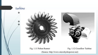
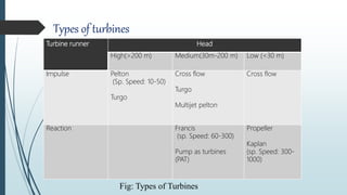
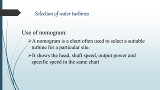
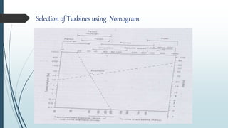
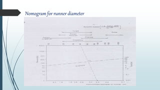
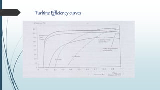
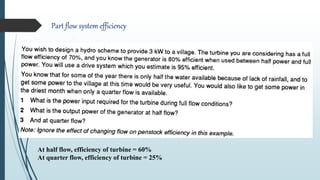
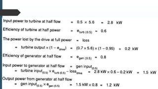
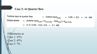
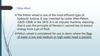
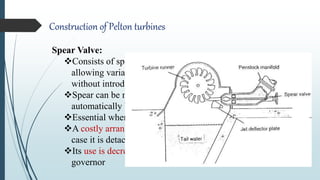
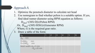
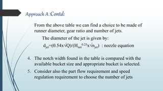
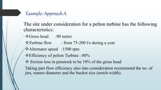
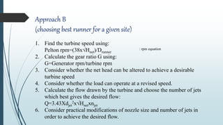
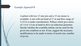
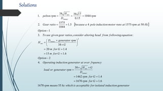
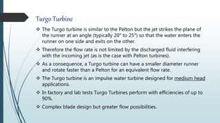
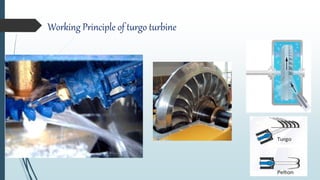
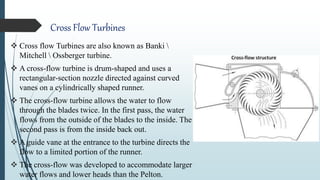
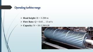
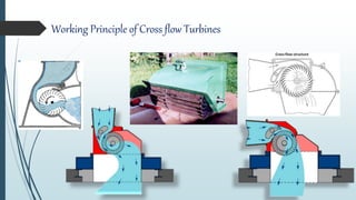
Turbines, drive system and governors
3.1. Turbine types for micro hydro,
their constructional features and operational characteristics,
Effect on efficiency during part flow conditions,
Nomogram and turbine selection,
Comparison of costs of the turbines
3.2. Introduction to drive system,
Various drive arrangements and their features,
Drive problem,
Design parameters for a drive system
3.3. Purpose of speed governing,
Various governing mechanisms,
Electrical load controller as a governor in micro hydro,
Ballast load, water cooled and air cooled ballasts,
Effect of ballast on generator sizing,
Ballast sizing.
Content
turbine
 Turbine is a hydro mechanical device that converts Potentio-kinetic energy
of water into mechanical energy which is supplied to generators for
electrical power generation.
 The turbine types widely used in MHP in Nepal are Pelton and cross flow.
 Cross-flow turbines are used at lower heads while the Pelton turbines are
used at higher heads.
Types of turbines
Principally, turbines are categorized as:
Impulse turbines
Reaction turbines
Impulse turbines: Rotates the runner by the impulse of
water jets by converting the pressure head into the velocity
head through nozzles.
Reaction turbines: Rotates the runner by the pressure head.
Fig: Types of Turbines
Turbine runner Head
High(>200 m) Medium(30m-200 m) Low (<30 m)
Impulse Pelton
(Sp. Speed: 10-50)
Turgo
Cross flow
Turgo
Multijet pelton
Cross flow
Reaction Francis
(sp. Speed: 60-300)
Pump as turbines
(PAT)
Propeller
Kaplan
(sp. Speed: 300-
1000)
Why impulse Turbine for micro hydro?
Are more tolerant of sand and other particles in the water
Allow better access to working parts;
Are easier to fabricate and maintain;
Are less subject to cavitation( although high head cause
high velocity can cause cavitation at the nozzle or on the
blades or the buckets).
Have flattery efficiency curves if a flow control device is
built in.
Selection of water turbines
Use of nomogram:
A nomogram is a chart often used to select a suitable
turbine for a particular site.
It shows the head, shaft speed, output power and
specific speed in the same chart
Selection of Turbines using Nomogram
Nomogram for runner diameter
Turbine Efficiency curves
Part flow system efficiency
At half flow, efficiency of turbine = 60%
At quarter flow, efficiency of turbine = 25%
Case 1: At full flow
Power input to turbine =
𝑜𝑢𝑡𝑝𝑢𝑡 𝑝𝑜𝑤𝑒𝑟
𝑒𝑓𝑓𝑖𝑐𝑖𝑒𝑛𝑐𝑦
=
𝑜𝑢𝑡𝑝𝑢𝑡 𝑝𝑜𝑤𝑒𝑟
𝜂𝑡𝑢𝑟𝑏𝑖𝑛𝑒
∗𝜂 𝑔𝑒𝑛𝑒𝑟𝑎𝑡𝑜𝑟
∗𝜂 𝑑𝑟𝑖𝑣𝑒
=
3
0.7∗0.8∗0.95
= 5.6 W
Case 2: At half flow
Case 3: At Quarter flow
Efficiencies at
Case 1: 53%
Case 2: 43%
Case 3: 7%
Pelton Wheel
The Pelton wheel is one of the most efficient type of
hydraulic turbine. It was invented by Lester Allan Pelton
(1829–1908) in the 1870. It is an impulse machine, meaning
that it uses the principle of Newton’s second law to extract
energy from a jet of fluid.
Pelton wheel is considered for use in dams where the flow
of water is low and medium to high water head is present.
Working Principle of pelton wheel
 The Pelton Turbine consists of a
wheel with a series of split buckets
set around its rim.
 A high velocity jet of water is
directed tangentially at the wheel.
 The jet hits each bucket and is split
in half, so that each half is turned
and deflected back almost through
180º.
 Nearly all the energy of the water
goes into propelling the bucket and
the deflected water falls into a
discharge channel below.
Blades of Pelton Wheel
Typical Arrangement of pelton wheel
Extraction of Energy by Pelton wheel
Construction of Pelton turbines
Main Parts:
 Runner
 Nozzle
 Shut off Valves
 Deflector Plate
 Spear Valve
Construction of Pelton turbines
Runner:
Consists of series of buckets mounted on the periphery of a circular
disc
Rotates when high speed water jet strikes into the bucket
Nozzle:
Small piece of pipe tapered at one end and connected to the penstock
manifold at the other end
Used to discharge the jet of water at high speed (hence high kinetic
energy) which strikes the bucket to cause rotation
Can be dissembled or reassembled to suit for seasonal variation of
discharge when needed
Construction of Pelton turbines
Shut off valves
 Usually a gate valve or a butterfly valve in turbine
manifold
 Should be fully open when the turbine operates
 They should be closed very slowly. If closed abruptly,
surge pressure created by high head can lead even to
bursting of pipes.
 It should not be used for flow regulation as the valve
can be damaged due to cavitation effects
Construction of Pelton turbines
Deflector Plate
 Used to deflect the water jet away from the buckets when
made to rotate into the water path
 Useful device to stop the turbine without shutting of the
penstock flow
 Also used for emergency shut down
 Allows water to hit buckets when a circular disc attached to
the deflector arm is fixed magnetically to an electromagnet
and blocks water to hit the runner when electromagnet is
demagnetized.
Construction of Pelton turbines
Spear Valve:
Consists of spear head arranged to move within the nozzle
allowing variation in effective orifice cross sectional area
without introducing energy losses
Spear can be moved either by turning a thread manually or
automatically by a mechanical speed governor
Essential when continuous flow regulation is required
A costly arrangement and also may block the penstock flow in
case it is detached accidentally when turbine is running
Its use is decreasing due to invention of ELC as speed
governor
How to increase runner speed?
Increase no. of jets.
Increase the no of runner in a shaft(Twin Runner)
Sizing of Pelton turbines
Two approaches:
Approach A:
Giving required dimensions to a local manufacturer who
already has some standard buckets
Approach B :
Pelton runner of specific diameter, complete with buckets
are available. Choose the best runner for a particular site.
njet 1 2 3 4 5 6
djet mm
D=6Xdjet mm
D=20Xdjet mm
Notch width>djet+5 mm
<djet+20 mm
Approach A
1. Optimize the penstock diameter to calculate net head
2. Use nomogram to find whether pelton is a suitable option. If yes,
find ideal runner diameter using RPM equation as follows:
Dideal=(38X√H)/(Pelton RPM)
Or, Dideal=(38X√HXG)/(Generator RPM)
Where, G is the required gear ratio.
3. Draw a table of the form:
Approach A :Contd:
From the above table we can find a choice to be made of
runner diameter, gear ratio and number of jets.
The diameter of the jet is given by:
djet=(0.54x√Q)/(Hnet
0.25x√njet) : nozzle equation
4. The notch width found in the table is compared with the
available bucket size and appropriate bucket is selected.
5. Consider also the part flow requirement and speed
regulation requirement to choose the number of jets
Example: Approach A
The site under consideration for a pelton turbine has the following
characteristics:
Gross head :90 meter
Turbine flow : from 75-200 l/s during a year
Alternator speed :1500 rpm
Efficiency of pelton Turbine : 80%
 friction loss in penstock to be 10% of the gross head
Taking part flow efficiency also into consideration recommend the no. of
jets, runner diameter and the bucket size (notch-width).
Approach B
(choosing best runner for a given site)
1. Find the turbine speed using:
Pelton rpm=(38x√Hnet)/Drunner
: rpm equation
2. Calculate the gear ratio G using:
G=Generator rpm/turbine rpm
3. Consider whether the net head can be altered to achieve a desirable
turbine speed
4. Consider whether the load can operate at a revised speed.
5. Calculate the flow drawn by the turbine and choose the number of jets
which best gives the desired flow:
Q=3.43Xdjet
2x√Hnetxnjet
6. Consider practical modifications of nozzle size and number of jets in
order to achieve the desired flow.
Example: Approach B
A pelton with two 13 mm jets and a 15 cm runner is
available. A site with net head of 17 m and flow range of
5-14 l/s is under consideration. Pulleys which give ratios
of 1.4 or 1.6 are at hand to drive an induction generator.
Decide whether the available turbine can be used for the
given site condition or not. If not, suggest the necessary
modifications to be made in terms of nozzle size, number
of jet etc.
Solutions
 
generatorinductionisolatedforacceptableiswhichhzmeansrpm
Gforrpm
Gforrpm
D
GH
rpmgeneratororload
frquencyoveratgeneratorinductionOperating
Option
Gform
Gform
G
rpmgeneratorD
H
equationfollowingfromheadalteringconsiderratiosgeargivenuseTo
Option
HzatrpmatrunsmotorinductionpoleabecauseratioGear
rpm
D
H
rpmpelton
runner
net
runner
net
runner
net
551670
6.11670
4.11462
38
.4
2
6.115
4.120
38
:,.3
1
50157545.1
1044
1575
.2
1044
15.0
173838
.1
2



















Accommodating available flow:
Flow drawn by two jet pelton is given by:
Increasing the nozzle aperture to 15 mm instead of 13 mm, we get
Q=6.4 l/s which is not much difference.
Adding 2 more jets and increasing the nozzle aperture to 16 mm
will absorb a flow of 14 l/s.
sl
nHdQ jetnetjet
/8.4
217013.043.3
43.3
2
2



Single jet Versus Multi jets
Single jet used traditionally due to complexity of flow
control governing
Multi jet emerged with the advent of load control governing
to capture the following advantages:
Higher rotational speed
Smaller runner and case
Flow control without spear valve
Less chance of blockage leading to reduced surge
pressure
Single jet Versus Multi jets
Multi jet arrangement has however the following disadvantages:
 Possibility of jet interference on incorrectly designed
systems
 Complexities of manifolds and manifold friction losses
 If flow control governing is required, it becomes
prohibitively complex
Turgo Turbine
 The Turgo turbine is similar to the Pelton but the jet strikes the plane of
the runner at an angle (typically 20° to 25°) so that the water enters the
runner on one side and exits on the other.
 Therefore the flow rate is not limited by the discharged fluid interfering
with the incoming jet (as is the case with Pelton turbines).
 As a consequence, a Turgo turbine can have a smaller diameter runner
and rotate faster than a Pelton for an equivalent flow rate.
 The Turgo turbine is an impulse water turbine designed for medium head
applications.
 In factory and lab tests Turgo Turbines perform with efficiencies of up to
90%.
 Complex blade design but greater flow possibilities.
Working Principle of turgo turbine
Cross Flow Turbines
 Cross flow Turbines are also known as Banki 
Mitchell  Ossberger turbine.
 A cross-flow turbine is drum-shaped and uses a
rectangular-section nozzle directed against curved
vanes on a cylindrically shaped runner.
 The cross-flow turbine allows the water to flow
through the blades twice. In the first pass, the water
flows from the outside of the blades to the inside. The
second pass is from the inside back out.
 A guide vane at the entrance to the turbine directs the
flow to a limited portion of the runner.
 The cross-flow was developed to accommodate larger
water flows and lower heads than the Pelton.
Operating turbine range
 Head height: H = 3-200 m
 Flow Rate: Q = 0.03… 13 m³/s
 Capacity: N = 10-3,500 kW
Working Principle of Cross flow Turbines
Construction of cross flow turbines
Runner
Drum shaped runner consisting of two parallel discs
connected together near their rims by a series of curved
blades
Runner shaft horizontal to the ground in all cases
Construction of cross flow turbines
Nozzle
Rectangular nozzle directs the water jet to the full length
of the runner
Water coming out of the nozzle imparts most of its kinetic
energy, passes through the runner and strikes the blade on
exit imparting a smaller amount of energy before leaving
the turbine
Guide Vane
 Guides the flow of water to the runner.
Construction of cross flow turbines
Draft tube (Optional):
A partial vacuum inside the casing can be induced by fitting a draft
tube below the runner which remains full of tail water at all times.
Any decrease in the water level induces a greater vacuum to increase
the effective head driving the cross flow.
The vacuum induction is limited by air bleed valve in the casing.
Careful design of the valve and casing is necessary to avoid
conditions where water might back up and submerge the runner.
This is a costly affair where availability of required head is not a
problem
Sizing a Crossflow
Diameter of the runner
Drunner= 40x(Hnet/cross flow rpm), where Hnet is the net head
Thickness of the water jet
tjet=0.1 x Drunner to 0.2 x Drunner
We know, the discharge is given by,
Q=Anozzle x √(2xgxHnet)
=tjetxjet width x √(2xgxHnet)
=tjetxLrunner x √(2xgxHnet)
Where, Anozzle is the cross section area of the nozzle and Lrunner is the length of the runner
Hence,
Lrunner=Q/(tjet x √(2xgxHnet)
=0.23 x Q/(tjet x √Hnet)
Runner length vs. Output power
Because of symmetry, runner length can be increased
without changing the hydraulic characteristics of the turbine
to increase the power (Doubling the runner length will
double the power output at the same speed)
The lower the head, the longer the runner becomes and
conversely on high heads, the crossflow runner tends to be
compact.
Too long blades will lead to fatigue at junction of the blades
and the disc
Intermediate bracing discs can be placed to avoid fatigue
but efficiency reduces as water interferes with the bracings.
Efficiency improvement
Efficiency is maintained
over a wider flow range
using partition device which
allows a third or two third of
the runner to be closed off.
Advantages
Simple design
Suitable for wide range of head and power
Simple fabrication technique
Comparison of costs of the turbines
References
 Adam Harvey, “Micro-hydro design manual”
 Tri Ratna Bajracharya, “Mini and Micro Hydropower System
Design”
 Tokyo Electric Power Co. (TEPCO)
 khullabs.com
 A. H. Umar Bhatti, A. Siddiqque, T. Iqbal,”Hydraulic turbines”

Lecture 3.1 Turbines in Micro Hydro

  • 1.
  • 2.
    3.1. Turbine typesfor micro hydro, their constructional features and operational characteristics, Effect on efficiency during part flow conditions, Nomogram and turbine selection, Comparison of costs of the turbines 3.2. Introduction to drive system, Various drive arrangements and their features, Drive problem, Design parameters for a drive system 3.3. Purpose of speed governing, Various governing mechanisms, Electrical load controller as a governor in micro hydro, Ballast load, water cooled and air cooled ballasts, Effect of ballast on generator sizing, Ballast sizing. Content
  • 3.
    turbine  Turbine isa hydro mechanical device that converts Potentio-kinetic energy of water into mechanical energy which is supplied to generators for electrical power generation.  The turbine types widely used in MHP in Nepal are Pelton and cross flow.  Cross-flow turbines are used at lower heads while the Pelton turbines are used at higher heads.
  • 4.
    Types of turbines Principally,turbines are categorized as: Impulse turbines Reaction turbines Impulse turbines: Rotates the runner by the impulse of water jets by converting the pressure head into the velocity head through nozzles. Reaction turbines: Rotates the runner by the pressure head. Fig: Types of Turbines Turbine runner Head High(>200 m) Medium(30m-200 m) Low (<30 m) Impulse Pelton (Sp. Speed: 10-50) Turgo Cross flow Turgo Multijet pelton Cross flow Reaction Francis (sp. Speed: 60-300) Pump as turbines (PAT) Propeller Kaplan (sp. Speed: 300- 1000)
  • 5.
    Why impulse Turbinefor micro hydro? Are more tolerant of sand and other particles in the water Allow better access to working parts; Are easier to fabricate and maintain; Are less subject to cavitation( although high head cause high velocity can cause cavitation at the nozzle or on the blades or the buckets). Have flattery efficiency curves if a flow control device is built in.
  • 6.
    Selection of waterturbines Use of nomogram: A nomogram is a chart often used to select a suitable turbine for a particular site. It shows the head, shaft speed, output power and specific speed in the same chart
  • 7.
    Selection of Turbinesusing Nomogram
  • 8.
  • 9.
  • 10.
    Part flow systemefficiency At half flow, efficiency of turbine = 60% At quarter flow, efficiency of turbine = 25%
  • 11.
    Case 1: Atfull flow Power input to turbine = 𝑜𝑢𝑡𝑝𝑢𝑡 𝑝𝑜𝑤𝑒𝑟 𝑒𝑓𝑓𝑖𝑐𝑖𝑒𝑛𝑐𝑦 = 𝑜𝑢𝑡𝑝𝑢𝑡 𝑝𝑜𝑤𝑒𝑟 𝜂𝑡𝑢𝑟𝑏𝑖𝑛𝑒 ∗𝜂 𝑔𝑒𝑛𝑒𝑟𝑎𝑡𝑜𝑟 ∗𝜂 𝑑𝑟𝑖𝑣𝑒 = 3 0.7∗0.8∗0.95 = 5.6 W Case 2: At half flow
  • 12.
    Case 3: AtQuarter flow Efficiencies at Case 1: 53% Case 2: 43% Case 3: 7%
  • 13.
    Pelton Wheel The Peltonwheel is one of the most efficient type of hydraulic turbine. It was invented by Lester Allan Pelton (1829–1908) in the 1870. It is an impulse machine, meaning that it uses the principle of Newton’s second law to extract energy from a jet of fluid. Pelton wheel is considered for use in dams where the flow of water is low and medium to high water head is present.
  • 14.
    Working Principle ofpelton wheel  The Pelton Turbine consists of a wheel with a series of split buckets set around its rim.  A high velocity jet of water is directed tangentially at the wheel.  The jet hits each bucket and is split in half, so that each half is turned and deflected back almost through 180º.  Nearly all the energy of the water goes into propelling the bucket and the deflected water falls into a discharge channel below.
  • 15.
  • 16.
  • 17.
    Extraction of Energyby Pelton wheel
  • 18.
    Construction of Peltonturbines Main Parts:  Runner  Nozzle  Shut off Valves  Deflector Plate  Spear Valve
  • 19.
    Construction of Peltonturbines Runner: Consists of series of buckets mounted on the periphery of a circular disc Rotates when high speed water jet strikes into the bucket Nozzle: Small piece of pipe tapered at one end and connected to the penstock manifold at the other end Used to discharge the jet of water at high speed (hence high kinetic energy) which strikes the bucket to cause rotation Can be dissembled or reassembled to suit for seasonal variation of discharge when needed
  • 20.
    Construction of Peltonturbines Shut off valves  Usually a gate valve or a butterfly valve in turbine manifold  Should be fully open when the turbine operates  They should be closed very slowly. If closed abruptly, surge pressure created by high head can lead even to bursting of pipes.  It should not be used for flow regulation as the valve can be damaged due to cavitation effects
  • 21.
    Construction of Peltonturbines Deflector Plate  Used to deflect the water jet away from the buckets when made to rotate into the water path  Useful device to stop the turbine without shutting of the penstock flow  Also used for emergency shut down  Allows water to hit buckets when a circular disc attached to the deflector arm is fixed magnetically to an electromagnet and blocks water to hit the runner when electromagnet is demagnetized.
  • 22.
    Construction of Peltonturbines Spear Valve: Consists of spear head arranged to move within the nozzle allowing variation in effective orifice cross sectional area without introducing energy losses Spear can be moved either by turning a thread manually or automatically by a mechanical speed governor Essential when continuous flow regulation is required A costly arrangement and also may block the penstock flow in case it is detached accidentally when turbine is running Its use is decreasing due to invention of ELC as speed governor
  • 23.
    How to increaserunner speed? Increase no. of jets. Increase the no of runner in a shaft(Twin Runner)
  • 24.
    Sizing of Peltonturbines Two approaches: Approach A: Giving required dimensions to a local manufacturer who already has some standard buckets Approach B : Pelton runner of specific diameter, complete with buckets are available. Choose the best runner for a particular site.
  • 25.
    njet 1 23 4 5 6 djet mm D=6Xdjet mm D=20Xdjet mm Notch width>djet+5 mm <djet+20 mm Approach A 1. Optimize the penstock diameter to calculate net head 2. Use nomogram to find whether pelton is a suitable option. If yes, find ideal runner diameter using RPM equation as follows: Dideal=(38X√H)/(Pelton RPM) Or, Dideal=(38X√HXG)/(Generator RPM) Where, G is the required gear ratio. 3. Draw a table of the form:
  • 26.
    Approach A :Contd: Fromthe above table we can find a choice to be made of runner diameter, gear ratio and number of jets. The diameter of the jet is given by: djet=(0.54x√Q)/(Hnet 0.25x√njet) : nozzle equation 4. The notch width found in the table is compared with the available bucket size and appropriate bucket is selected. 5. Consider also the part flow requirement and speed regulation requirement to choose the number of jets
  • 27.
    Example: Approach A Thesite under consideration for a pelton turbine has the following characteristics: Gross head :90 meter Turbine flow : from 75-200 l/s during a year Alternator speed :1500 rpm Efficiency of pelton Turbine : 80%  friction loss in penstock to be 10% of the gross head Taking part flow efficiency also into consideration recommend the no. of jets, runner diameter and the bucket size (notch-width).
  • 28.
    Approach B (choosing bestrunner for a given site) 1. Find the turbine speed using: Pelton rpm=(38x√Hnet)/Drunner : rpm equation 2. Calculate the gear ratio G using: G=Generator rpm/turbine rpm 3. Consider whether the net head can be altered to achieve a desirable turbine speed 4. Consider whether the load can operate at a revised speed. 5. Calculate the flow drawn by the turbine and choose the number of jets which best gives the desired flow: Q=3.43Xdjet 2x√Hnetxnjet 6. Consider practical modifications of nozzle size and number of jets in order to achieve the desired flow.
  • 29.
    Example: Approach B Apelton with two 13 mm jets and a 15 cm runner is available. A site with net head of 17 m and flow range of 5-14 l/s is under consideration. Pulleys which give ratios of 1.4 or 1.6 are at hand to drive an induction generator. Decide whether the available turbine can be used for the given site condition or not. If not, suggest the necessary modifications to be made in terms of nozzle size, number of jet etc.
  • 30.
  • 31.
    Accommodating available flow: Flowdrawn by two jet pelton is given by: Increasing the nozzle aperture to 15 mm instead of 13 mm, we get Q=6.4 l/s which is not much difference. Adding 2 more jets and increasing the nozzle aperture to 16 mm will absorb a flow of 14 l/s. sl nHdQ jetnetjet /8.4 217013.043.3 43.3 2 2   
  • 32.
  • 33.
    Single jet VersusMulti jets Single jet used traditionally due to complexity of flow control governing Multi jet emerged with the advent of load control governing to capture the following advantages: Higher rotational speed Smaller runner and case Flow control without spear valve Less chance of blockage leading to reduced surge pressure
  • 34.
    Single jet VersusMulti jets Multi jet arrangement has however the following disadvantages:  Possibility of jet interference on incorrectly designed systems  Complexities of manifolds and manifold friction losses  If flow control governing is required, it becomes prohibitively complex
  • 35.
    Turgo Turbine  TheTurgo turbine is similar to the Pelton but the jet strikes the plane of the runner at an angle (typically 20° to 25°) so that the water enters the runner on one side and exits on the other.  Therefore the flow rate is not limited by the discharged fluid interfering with the incoming jet (as is the case with Pelton turbines).  As a consequence, a Turgo turbine can have a smaller diameter runner and rotate faster than a Pelton for an equivalent flow rate.  The Turgo turbine is an impulse water turbine designed for medium head applications.  In factory and lab tests Turgo Turbines perform with efficiencies of up to 90%.  Complex blade design but greater flow possibilities.
  • 36.
    Working Principle ofturgo turbine
  • 37.
    Cross Flow Turbines Cross flow Turbines are also known as Banki Mitchell Ossberger turbine.  A cross-flow turbine is drum-shaped and uses a rectangular-section nozzle directed against curved vanes on a cylindrically shaped runner.  The cross-flow turbine allows the water to flow through the blades twice. In the first pass, the water flows from the outside of the blades to the inside. The second pass is from the inside back out.  A guide vane at the entrance to the turbine directs the flow to a limited portion of the runner.  The cross-flow was developed to accommodate larger water flows and lower heads than the Pelton.
  • 38.
    Operating turbine range Head height: H = 3-200 m  Flow Rate: Q = 0.03… 13 m³/s  Capacity: N = 10-3,500 kW
  • 39.
    Working Principle ofCross flow Turbines
  • 40.
    Construction of crossflow turbines Runner Drum shaped runner consisting of two parallel discs connected together near their rims by a series of curved blades Runner shaft horizontal to the ground in all cases
  • 41.
    Construction of crossflow turbines Nozzle Rectangular nozzle directs the water jet to the full length of the runner Water coming out of the nozzle imparts most of its kinetic energy, passes through the runner and strikes the blade on exit imparting a smaller amount of energy before leaving the turbine Guide Vane  Guides the flow of water to the runner.
  • 42.
    Construction of crossflow turbines Draft tube (Optional): A partial vacuum inside the casing can be induced by fitting a draft tube below the runner which remains full of tail water at all times. Any decrease in the water level induces a greater vacuum to increase the effective head driving the cross flow. The vacuum induction is limited by air bleed valve in the casing. Careful design of the valve and casing is necessary to avoid conditions where water might back up and submerge the runner. This is a costly affair where availability of required head is not a problem
  • 43.
    Sizing a Crossflow Diameterof the runner Drunner= 40x(Hnet/cross flow rpm), where Hnet is the net head Thickness of the water jet tjet=0.1 x Drunner to 0.2 x Drunner We know, the discharge is given by, Q=Anozzle x √(2xgxHnet) =tjetxjet width x √(2xgxHnet) =tjetxLrunner x √(2xgxHnet) Where, Anozzle is the cross section area of the nozzle and Lrunner is the length of the runner Hence, Lrunner=Q/(tjet x √(2xgxHnet) =0.23 x Q/(tjet x √Hnet)
  • 44.
    Runner length vs.Output power Because of symmetry, runner length can be increased without changing the hydraulic characteristics of the turbine to increase the power (Doubling the runner length will double the power output at the same speed) The lower the head, the longer the runner becomes and conversely on high heads, the crossflow runner tends to be compact. Too long blades will lead to fatigue at junction of the blades and the disc Intermediate bracing discs can be placed to avoid fatigue but efficiency reduces as water interferes with the bracings.
  • 45.
    Efficiency improvement Efficiency ismaintained over a wider flow range using partition device which allows a third or two third of the runner to be closed off.
  • 46.
    Advantages Simple design Suitable forwide range of head and power Simple fabrication technique
  • 47.
    Comparison of costsof the turbines
  • 48.
    References  Adam Harvey,“Micro-hydro design manual”  Tri Ratna Bajracharya, “Mini and Micro Hydropower System Design”  Tokyo Electric Power Co. (TEPCO)  khullabs.com  A. H. Umar Bhatti, A. Siddiqque, T. Iqbal,”Hydraulic turbines”

Editor's Notes

  • #8 Mark head and find turbine power from the discharge known. Eturbine = 65 to 80 percent for local crossfow 75 for pelton and turgo 80 for reaction Mark desire turbine speed and perpendicular
  • #10 The above figure shows the importance of part-flow performance in selecting equipment for a site. Assuming that flow-control devices are fitted, an important point to notice is that the Pelton and crossflow turbines retain high efficiency when below design flow; in contrast the Francis drops in efficiency, producing very poor power output if run at below half the normal flow, and fixed pitch propeller turbines are very poor except at 80 to 100percent of full flow. The Francis is a popular turbine in larger hydro schemes, but it is more complex and expensive and has poor part-flow efficiency. It is one of the few turbine which turns at a reasonable speed at certain power and head combinations. An impulse turbine operated under these conditions of head and flow would be much larger, expensive as a result of its size, cumbersomely slow-turning and would need a greater speed increasing transmission. In addition to giving high speed at low head-to-power ratios, reaction turbines are particularly suited to low head applications for a second reason. Since power conversion is caused partly by pressure difference across the blades, the drop in head below the blades (known as the suction head) is as effective in producing power as is the head above the turbine.
  • #13 Efficiency= output/input
  • #18 Splitter
  • #19 GOVERNING SYSTEM