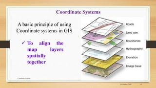
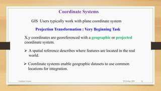
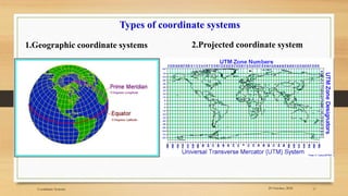
1) The document discusses coordinate systems used in GIS, specifically geographic and projected coordinate systems.
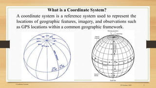
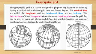
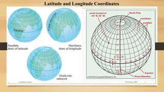
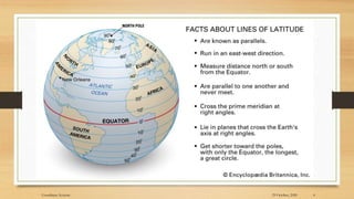
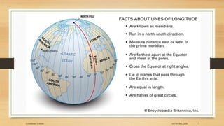
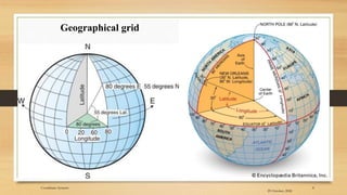
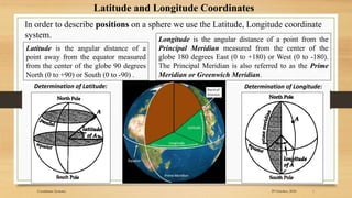
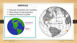
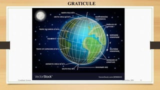
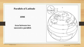
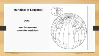
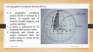
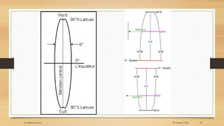
2) The basic coordinate system used to represent locations on Earth is latitude and longitude, which form a geographic grid.
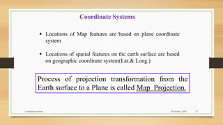
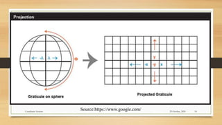
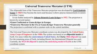
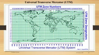
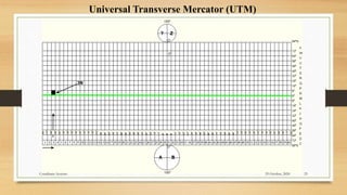
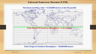
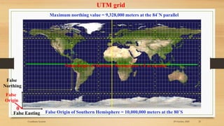
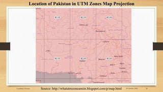
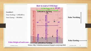
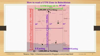
3) Projected coordinate systems like UTM transform latitude and longitude coordinates into plane coordinates for use in GIS.