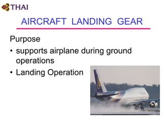
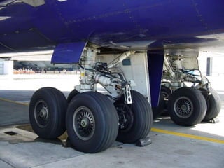
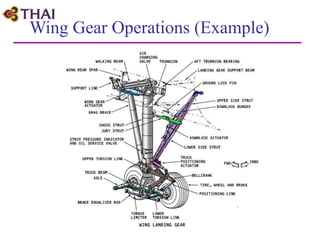
1) Aircraft landing gear supports the airplane during ground operations and absorbs shock during takeoff and landing.
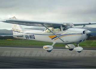
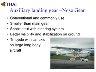
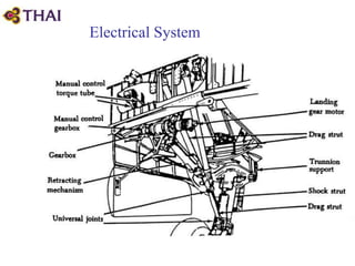
2) Landing gear can be retractable, allowing the gear to fold into the airplane to reduce drag, or fixed/non-retractable.
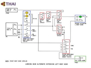
3) Retractable gear uses hydraulic, electric, or emergency systems to extend and retract the gear. Fixed gear absorbs stresses through shock absorption components like springs or shock struts.