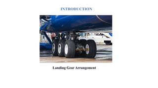
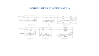
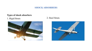
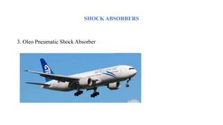
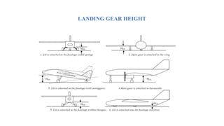
KLE Dr M S Sheshgiri
College of Engineering and Technology,
Udyambag, Belagavi – 590008
Department of Mechanical Engineering
(NBAAccredited)
Seminar Presentation
by
Naveen Ullegaddi
2KL19ME044
“Landing Gear Arrangement Analysis”
Under the Guidance of
Prof. B. G. Koujalagi
Associate Professor
Department of Mechanical Engineering
CONTENTS
1. INTRODUCTION
2. OBJECTIVES
3. LANDING CONFIGURATION
4. SHOCK ABSORBERS
5. LANDING GEAR GEOMETRY
6. LANDING GEAR HEIGHT
7. CONCLUSION
8. REFERENCES
INTRODUCTION
The landing gear is a vital subsystem of the aircraft. The landing gear supports the aircraft when it’s
not flying. The main purpose of a landing system is to decrease impact loads by absorbing them
while landing. It also must offer suspension, wheel steering, and braking while the aircraft is taxiing
on the airstrip. The design of this undercarriage is one of the fundamental aspects of the design of
aircraft. At the time of landing, the landing gear is subjected to repeated stresses due to thrust on the
upper part. Due to repetitive stresses, landing gear may fail. The failure of landing gear at the time of
landing can have adverse effects on the aircraft. Therefore, the landing gear must be able to resist the
impact of landing.
INTRODUCTION
Landing Gear Arrangement
OBJECTIVES
1. To keep the aircraft stable on the ground and during loading taxiing and landing.
2. To allow the aircraft to freely move during taxing.
3. To provide a safe distance between other aircraft components such as wing and fuselage while
the aircraft is on the ground position to prevent any damage by ground contact.
4. To absorb the landing shocks during the landing operation
5. To facilitate take-off by allowing aircraft acceleration and rotation with the lowest friction.
LANDING GEAR CONFIGURATION
SHOCK ABSORBERS
Types of shock absorbers
1. Rigid Struts 2. Steel Struts
SHOCK ABSORBERS
3. Oleo Pneumatic Shock Absorber
LANDING GEAR GEOMETRY
At this point, the landing gear configuration is selected and the retraction configuration is decided.
Now, the designer needs to perform mathematical calculations to determine a few parameters such as
height, wheelbase, wheel track, and the distance between the main gear and the aircraft’s center of
gravity. These parameters are interrelated through geometrical relations and several mathematical
principles. These relationships are described in this Section. The guidelines for determining these
parameters are presented in the following subsequent sections.
LANDING GEAR GEOMETRY
LANDING GEAR HEIGHT
There are mainly five design requirements in which landing gear height plays an important role. They
are:
1. Landing gear height provides aircraft clearance during taxi.
2. Landing gear height provides rear fuselage clearance during take-off rotation.
3. Landing gear height contributes to tip-back prevention.
4. Landing gear height contributes to overturning prevention.
5. Landing gear height satisfies loading and unloading requirements.
LANDING GEAR HEIGHT
CONCLUSION
Different systems of landing gears are present out of which few are obsolete now. At an early age landing gear
development went on from two wheels only which later on scattered to various wheels arrangement. For General
Aviation industries now a day’s only the following system is in use:
1. Tail-gear
2. Tricycle or nose-gear
3. Quadricycle
4. Multi-bogey
99% of the aircraft are using the same system which is shown above. Out of the above-shown list, the Nose gear
arrangement is more popular due to its added advantage as compared to other systems. Off course here comes
the weight parameter also depending on the weight of the aircraft and the available space system the
arrangement can shift to Multi bogey system as well
REFERENCES
1. “Divakaran V. N” Landing gear design and development
2. “Pritham Nutakki” Modelling and structural analysis of aircraft landing gear
3. “Derek Morrison” Aircraft Landing Gear Simulation and Analysis
4. “Muhammed Faizal Elayancheri” Design and Linear Static Analysis of
Landing Gear
THANK YOU

Naveen Ullegaddi.pptx

  • 1.
    KLE Dr MS Sheshgiri College of Engineering and Technology, Udyambag, Belagavi – 590008 Department of Mechanical Engineering (NBAAccredited) Seminar Presentation by Naveen Ullegaddi 2KL19ME044 “Landing Gear Arrangement Analysis” Under the Guidance of Prof. B. G. Koujalagi Associate Professor Department of Mechanical Engineering
  • 2.
    CONTENTS 1. INTRODUCTION 2. OBJECTIVES 3.LANDING CONFIGURATION 4. SHOCK ABSORBERS 5. LANDING GEAR GEOMETRY 6. LANDING GEAR HEIGHT 7. CONCLUSION 8. REFERENCES
  • 3.
    INTRODUCTION The landing gearis a vital subsystem of the aircraft. The landing gear supports the aircraft when it’s not flying. The main purpose of a landing system is to decrease impact loads by absorbing them while landing. It also must offer suspension, wheel steering, and braking while the aircraft is taxiing on the airstrip. The design of this undercarriage is one of the fundamental aspects of the design of aircraft. At the time of landing, the landing gear is subjected to repeated stresses due to thrust on the upper part. Due to repetitive stresses, landing gear may fail. The failure of landing gear at the time of landing can have adverse effects on the aircraft. Therefore, the landing gear must be able to resist the impact of landing.
  • 4.
  • 5.
    OBJECTIVES 1. To keepthe aircraft stable on the ground and during loading taxiing and landing. 2. To allow the aircraft to freely move during taxing. 3. To provide a safe distance between other aircraft components such as wing and fuselage while the aircraft is on the ground position to prevent any damage by ground contact. 4. To absorb the landing shocks during the landing operation 5. To facilitate take-off by allowing aircraft acceleration and rotation with the lowest friction.
  • 6.
  • 7.
    SHOCK ABSORBERS Types ofshock absorbers 1. Rigid Struts 2. Steel Struts
  • 8.
    SHOCK ABSORBERS 3. OleoPneumatic Shock Absorber
  • 10.
    LANDING GEAR GEOMETRY Atthis point, the landing gear configuration is selected and the retraction configuration is decided. Now, the designer needs to perform mathematical calculations to determine a few parameters such as height, wheelbase, wheel track, and the distance between the main gear and the aircraft’s center of gravity. These parameters are interrelated through geometrical relations and several mathematical principles. These relationships are described in this Section. The guidelines for determining these parameters are presented in the following subsequent sections.
  • 11.
  • 12.
    LANDING GEAR HEIGHT Thereare mainly five design requirements in which landing gear height plays an important role. They are: 1. Landing gear height provides aircraft clearance during taxi. 2. Landing gear height provides rear fuselage clearance during take-off rotation. 3. Landing gear height contributes to tip-back prevention. 4. Landing gear height contributes to overturning prevention. 5. Landing gear height satisfies loading and unloading requirements.
  • 13.
  • 14.
    CONCLUSION Different systems oflanding gears are present out of which few are obsolete now. At an early age landing gear development went on from two wheels only which later on scattered to various wheels arrangement. For General Aviation industries now a day’s only the following system is in use: 1. Tail-gear 2. Tricycle or nose-gear 3. Quadricycle 4. Multi-bogey 99% of the aircraft are using the same system which is shown above. Out of the above-shown list, the Nose gear arrangement is more popular due to its added advantage as compared to other systems. Off course here comes the weight parameter also depending on the weight of the aircraft and the available space system the arrangement can shift to Multi bogey system as well
  • 15.
    REFERENCES 1. “Divakaran V.N” Landing gear design and development 2. “Pritham Nutakki” Modelling and structural analysis of aircraft landing gear 3. “Derek Morrison” Aircraft Landing Gear Simulation and Analysis 4. “Muhammed Faizal Elayancheri” Design and Linear Static Analysis of Landing Gear
  • 16.