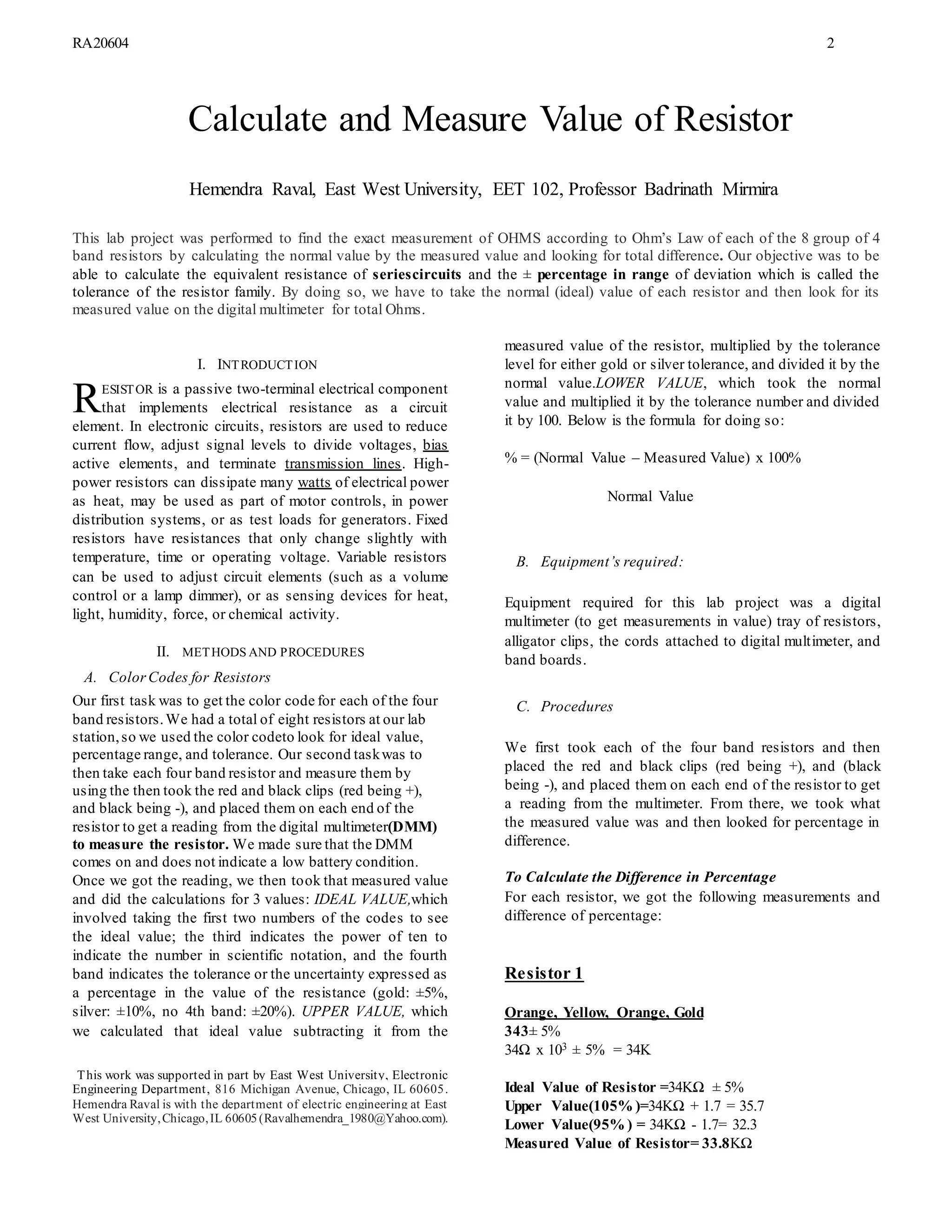
MA20578 1
Four Resistors being Calculated by the theory and measuredby using the Digital Multimeter on 01/26/2018
Take-Home Messages
 What are the innovative features of utilizing electromagnetics for biomedical applications in this manuscript,
in one sentence?
 What is the conclusion in this manuscript, in one sentence?
 What are the targeted biological and/or medical applications, in one sentence?
 What is the significance/breakthrough of this work?
 Accomplishments in this manuscript you would like to highlight that are not mention above, for our readers,
in one sentence?
CALCULATE AND MEASURE THE VALUE
OF RESISTOR
Hemendra Raval, East West University, EET 102, Professor Badrinath Mirmira
This page does not count for the maximum 6 or 10 page limit. The Visual Summary and Take-Home Messages are uploaded
separately during the final manuscript upload. The information in this page should not exceed one page.
RA20604 2
This lab project was performed to find the exact measurement of OHMS according to Ohm’s Law of each of the 8 group of 4
band resistors by calculating the normal value by the measured value and looking for total difference. Our objective was to be
able to calculate the equivalent resistance of seriescircuits and the ± percentage in range of deviation which is called the
tolerance of the resistor family. By doing so, we have to take the normal (ideal) value of each resistor and then look for its
measured value on the digital multimeter for total Ohms.
I. INTRODUCTION1
ESISTOR is a passive two-terminal electrical component
that implements electrical resistance as a circuit
element. In electronic circuits, resistors are used to reduce
current flow, adjust signal levels to divide voltages, bias
active elements, and terminate transmission lines. High-
power resistors can dissipate many watts of electrical power
as heat, may be used as part of motor controls, in power
distribution systems, or as test loads for generators. Fixed
resistors have resistances that only change slightly with
temperature, time or operating voltage. Variable resistors
can be used to adjust circuit elements (such as a volume
control or a lamp dimmer), or as sensing devices for heat,
light, humidity, force, or chemical activity.
II. METHODS AND PROCEDURES
A. ColorCodes for Resistors
Our first task was to get the color code for each of the four
band resistors.We had a total of eight resistors at our lab
station,so we used the color codeto look for ideal value,
percentage range, and tolerance. Our second taskwas to
then take each four band resistor and measure them by
using the then took the red and black clips (red being +),
and black being -), and placed them on each end of the
resistor to get a reading from the digital multimeter(DMM)
to measure the resistor. We made sure that the DMM
comes on and does not indicate a low battery condition.
Once we got the reading, we then took that measured value
and did the calculations for 3 values: IDEAL VALUE,which
involved taking the first two numbers of the codes to see
the ideal value; the third indicates the power of ten to
indicate the number in scientific notation, and the fourth
band indicates the tolerance or the uncertainty expressed as
a percentage in the value of the resistance (gold: ±5%,
silver: ±10%, no 4th band: ±20%). UPPER VALUE, which
we calculated that ideal value subtracting it from the
1
This work was supported in part by East West University, Electronic
Engineering Department, 816 Michigan Avenue, Chicago, IL 60605.
Hemendra Raval is with the department of electric engineering at East
West University,Chicago,IL 60605(Ravalhemendra_1980@Yahoo.com).
measured value of the resistor, multiplied by the tolerance
level for either gold or silver tolerance, and divided it by the
normal value.LOWER VALUE, which took the normal
value and multiplied it by the tolerance number and divided
it by 100. Below is the formula for doing so:
% = (Normal Value – Measured Value) x 100%
Normal Value
B. Equipment’s required:
Equipment required for this lab project was a digital
multimeter (to get measurements in value) tray of resistors,
alligator clips, the cords attached to digital multimeter, and
band boards.
C. Procedures
We first took each of the four band resistors and then
placed the red and black clips (red being +), and (black
being -), and placed them on each end of the resistor to get
a reading from the multimeter. From there, we took what
the measured value was and then looked for percentage in
difference.
To Calculate the Difference in Percentage
For each resistor, we got the following measurements and
difference of percentage:
Resistor 1
Orange, Yellow, Orange, Gold
343± 5%
34Ω x 103 ± 5% = 34K
Ideal Value of Resistor =34KΩ ± 5%
Upper Value(105% )=34KΩ + 1.7 = 35.7
Lower Value(95% ) = 34KΩ - 1.7= 32.3
Measured Value of Resistor= 33.8KΩ
Calculate and Measure Value of Resistor
Hemendra Raval, East West University, EET 102, Professor Badrinath Mirmira
R
MA20578 3
Difference Value = 0.2KΩ
Difference in Percentage = 0.58%
Resistor 2
Yellow, Violet, Red, Gold
4 7 2± 5%
4.7 k Ω x 102 ± 5%
Ideal Value of Resistor =4.7KΩ ± 5%
Upper Value (105% ) =4.7KΩ + 0.235 = 4.94KΩ
Lower Value(95% ) = 4.7KΩ - 0.235= 4.47KΩ
Measured Value of Resistor= 4.61KΩ
Difference Value = 0.09KΩ
Difference in Percentage = 1.91%
Resistor 3
Yellow, Violet, Brown, Gold
4 7 1 ± 5%
47 x 101± 5% = 470Ω
Ideal Value of Resistor = 470Ω ± 5%
Upper Value (105% ) = 470 + 23.5 = 494Ω
Lower Value(95% ) = 470 - 23.5 = 447Ω
Measured Value of Resistor= 463Ω
Difference Value = 7Ω
Difference in Percentage = 1.98%
Resistor 4
Orange, White, Orange, Gold
3 9 3 ± 5%
39 x 103 = 39KΩ
Ideal Value of Resistor =39kΩ ± 5%
Upper Value (105% ) =39+ 2 = 41KΩ
Lower Value(95% ) = 39 - 2 = 37KΩ
Measured Value of Resistor= 38.9KΩ
Difference Value = 0.1KΩ
Difference in Percentage = 0.256%
D. Final Stage
We then determined each of the final percentage in
difference of each resistor after testing for measured value,
and calculating them according to the formula given.
III. RESULTS
Part I of our lab included:
We took the 4 (Four) resistors and calculated and meas
ure the value.
R1 color coding, Orange, Yellow, Orange Gold= 34K
R2 color coding, Red, violet, Red, gold = 4.7K
R3 color coding, Yellow, Violet, Brown, gold = 470
R4 color coding, Orange, White, Orange gold = 39K
Tolerance Color Codes:
Noband = 20%; silver = 10%; gold= 5%;
IV. CONCLUSION
In summary, we found that we had to use the same three
band resistor of that reads grey red, red, and gold to then
proceed for lab 2. However, we found that.
REFERENCES
[1] Sengpiel Audio, “Ohm’s Law: Calculator and all Formulas (Online
Sources)”.
[2] Put author here, Component symbols and simple circuits (Online
Source),” M ST Workbooks
[3] Mitchele E. Shultz,Grob’s Basic Electronics. 11th
Revised Edition,
2011, ch. 4.
[4] Online Source, “Circuits of Today,” published.
[5] (Basic Book/Monograph Online Sources),“All About Circuits”
ONLINE.Available:
https://www.allaboutcircuits.com/textbook/direct-current/

Lab report calculate & measure value of resistor lab 01

  • 1.
    MA20578 1 Four Resistorsbeing Calculated by the theory and measuredby using the Digital Multimeter on 01/26/2018 Take-Home Messages  What are the innovative features of utilizing electromagnetics for biomedical applications in this manuscript, in one sentence?  What is the conclusion in this manuscript, in one sentence?  What are the targeted biological and/or medical applications, in one sentence?  What is the significance/breakthrough of this work?  Accomplishments in this manuscript you would like to highlight that are not mention above, for our readers, in one sentence? CALCULATE AND MEASURE THE VALUE OF RESISTOR Hemendra Raval, East West University, EET 102, Professor Badrinath Mirmira This page does not count for the maximum 6 or 10 page limit. The Visual Summary and Take-Home Messages are uploaded separately during the final manuscript upload. The information in this page should not exceed one page.
  • 2.
    RA20604 2 This labproject was performed to find the exact measurement of OHMS according to Ohm’s Law of each of the 8 group of 4 band resistors by calculating the normal value by the measured value and looking for total difference. Our objective was to be able to calculate the equivalent resistance of seriescircuits and the ± percentage in range of deviation which is called the tolerance of the resistor family. By doing so, we have to take the normal (ideal) value of each resistor and then look for its measured value on the digital multimeter for total Ohms. I. INTRODUCTION1 ESISTOR is a passive two-terminal electrical component that implements electrical resistance as a circuit element. In electronic circuits, resistors are used to reduce current flow, adjust signal levels to divide voltages, bias active elements, and terminate transmission lines. High- power resistors can dissipate many watts of electrical power as heat, may be used as part of motor controls, in power distribution systems, or as test loads for generators. Fixed resistors have resistances that only change slightly with temperature, time or operating voltage. Variable resistors can be used to adjust circuit elements (such as a volume control or a lamp dimmer), or as sensing devices for heat, light, humidity, force, or chemical activity. II. METHODS AND PROCEDURES A. ColorCodes for Resistors Our first task was to get the color code for each of the four band resistors.We had a total of eight resistors at our lab station,so we used the color codeto look for ideal value, percentage range, and tolerance. Our second taskwas to then take each four band resistor and measure them by using the then took the red and black clips (red being +), and black being -), and placed them on each end of the resistor to get a reading from the digital multimeter(DMM) to measure the resistor. We made sure that the DMM comes on and does not indicate a low battery condition. Once we got the reading, we then took that measured value and did the calculations for 3 values: IDEAL VALUE,which involved taking the first two numbers of the codes to see the ideal value; the third indicates the power of ten to indicate the number in scientific notation, and the fourth band indicates the tolerance or the uncertainty expressed as a percentage in the value of the resistance (gold: ±5%, silver: ±10%, no 4th band: ±20%). UPPER VALUE, which we calculated that ideal value subtracting it from the 1 This work was supported in part by East West University, Electronic Engineering Department, 816 Michigan Avenue, Chicago, IL 60605. Hemendra Raval is with the department of electric engineering at East West University,Chicago,IL 60605(Ravalhemendra_1980@Yahoo.com). measured value of the resistor, multiplied by the tolerance level for either gold or silver tolerance, and divided it by the normal value.LOWER VALUE, which took the normal value and multiplied it by the tolerance number and divided it by 100. Below is the formula for doing so: % = (Normal Value – Measured Value) x 100% Normal Value B. Equipment’s required: Equipment required for this lab project was a digital multimeter (to get measurements in value) tray of resistors, alligator clips, the cords attached to digital multimeter, and band boards. C. Procedures We first took each of the four band resistors and then placed the red and black clips (red being +), and (black being -), and placed them on each end of the resistor to get a reading from the multimeter. From there, we took what the measured value was and then looked for percentage in difference. To Calculate the Difference in Percentage For each resistor, we got the following measurements and difference of percentage: Resistor 1 Orange, Yellow, Orange, Gold 343± 5% 34Ω x 103 ± 5% = 34K Ideal Value of Resistor =34KΩ ± 5% Upper Value(105% )=34KΩ + 1.7 = 35.7 Lower Value(95% ) = 34KΩ - 1.7= 32.3 Measured Value of Resistor= 33.8KΩ Calculate and Measure Value of Resistor Hemendra Raval, East West University, EET 102, Professor Badrinath Mirmira R
  • 3.
    MA20578 3 Difference Value= 0.2KΩ Difference in Percentage = 0.58% Resistor 2 Yellow, Violet, Red, Gold 4 7 2± 5% 4.7 k Ω x 102 ± 5% Ideal Value of Resistor =4.7KΩ ± 5% Upper Value (105% ) =4.7KΩ + 0.235 = 4.94KΩ Lower Value(95% ) = 4.7KΩ - 0.235= 4.47KΩ Measured Value of Resistor= 4.61KΩ Difference Value = 0.09KΩ Difference in Percentage = 1.91% Resistor 3 Yellow, Violet, Brown, Gold 4 7 1 ± 5% 47 x 101± 5% = 470Ω Ideal Value of Resistor = 470Ω ± 5% Upper Value (105% ) = 470 + 23.5 = 494Ω Lower Value(95% ) = 470 - 23.5 = 447Ω Measured Value of Resistor= 463Ω Difference Value = 7Ω Difference in Percentage = 1.98% Resistor 4 Orange, White, Orange, Gold 3 9 3 ± 5% 39 x 103 = 39KΩ Ideal Value of Resistor =39kΩ ± 5% Upper Value (105% ) =39+ 2 = 41KΩ Lower Value(95% ) = 39 - 2 = 37KΩ Measured Value of Resistor= 38.9KΩ Difference Value = 0.1KΩ Difference in Percentage = 0.256% D. Final Stage We then determined each of the final percentage in difference of each resistor after testing for measured value, and calculating them according to the formula given. III. RESULTS Part I of our lab included: We took the 4 (Four) resistors and calculated and meas ure the value. R1 color coding, Orange, Yellow, Orange Gold= 34K R2 color coding, Red, violet, Red, gold = 4.7K R3 color coding, Yellow, Violet, Brown, gold = 470 R4 color coding, Orange, White, Orange gold = 39K Tolerance Color Codes: Noband = 20%; silver = 10%; gold= 5%; IV. CONCLUSION In summary, we found that we had to use the same three band resistor of that reads grey red, red, and gold to then proceed for lab 2. However, we found that. REFERENCES [1] Sengpiel Audio, “Ohm’s Law: Calculator and all Formulas (Online Sources)”. [2] Put author here, Component symbols and simple circuits (Online Source),” M ST Workbooks [3] Mitchele E. Shultz,Grob’s Basic Electronics. 11th Revised Edition, 2011, ch. 4. [4] Online Source, “Circuits of Today,” published. [5] (Basic Book/Monograph Online Sources),“All About Circuits” ONLINE.Available: https://www.allaboutcircuits.com/textbook/direct-current/