This lab report summarizes two experiments measuring resistance and voltage. In the first experiment, the resistance of three resistors was calculated from their color codes and measured with a digital multimeter. The measured values were within 5% of the calculated values, validating the accuracy of using color codes. In the second experiment, the voltage output of a power supply was measured at increasing levels and found to be slightly lower than the power supply readings due to internal resistance dropping voltage. The experiments helped familiarize the student with lab equipment and electrical measurements.
Dear student, Cheap Assignment Help, an online tutoring company, provides students with a wide range of online assignment help services for students studying in classes K-12, and College or university. The Expert team of professional online assignment help tutors at Cheap Assignment Help .COM provides a wide range of help with assignments through services such as college assignment help, university assignment help, homework assignment help, email assignment help and online assignment help. Our expert team consists of passionate and professional assignment help tutors, having masters and PhD degrees from the best universities of the world, from different countries like Australia, United Kingdom, United States, Canada, UAE and many more who give the best quality and plagiarism free answers of the assignment help questions submitted by students, on sharp deadline. Cheap Assignment Help .COM tutors are available 24x7 to provide assignment help in diverse fields - Math, Chemistry, Physics, Writing, Thesis, Essay, Accounting, Finance, Data Analysis, Case Studies, Term Papers, and Projects etc. We also provide assistance to the problems in programming languages such as C/C++, Java, Python, Matlab, .Net, Engineering assignment help and Finance assignment help. The expert team of certified online tutors in diverse fields at Cheap Assignment Help .COM available around the clock (24x7) to provide live help to students with their assignment and questions. We have also excelled in providing E-education with latest web technology. The Students can communicate with our online assignment tutors using voice, video and an interactive white board. We help students in solving their problems, assignments, tests and in study plans. You will feel like you are learning from a highly skilled online tutor in person just like in classroom teaching. You can see what the tutor is writing, and at the same time you can ask the questions which arise in your mind. You only need a PC with Internet connection or a Laptop with Wi-Fi Internet access. We provide live online tutoring which can be accessed at anytime and anywhere according to student’s convenience. We have tutors in every subject such as Math, Chemistry, Biology, Physics and English whatever be the school level. Our college and university level tutors provide engineering online tutoring in areas such as Computer Science, Electrical and Electronics engineering, Mechanical engineering and Chemical engineering. Regards http://www.cheapassignmenthelp.com/ http://www.cheapassignmenthelp.co.uk/
2012 Unexpected failures due to dynamic avalanching caused by bipolar ESD stressSofics
2012 Taiwan ESD and reliability conference
The bipolar nature of ESD pulses such as MM introduces failure mechanisms that cannot be reproduced by TLP/HBM. A lowered breakdown voltage due to dynamic avalanching was observed. The key issue is that carriers injected during the first swing remain in the device after the current switches polarity. A case study for high-voltage diodes is presented.
Page 1 of 4 Direct Current (DC) Circuits Introduct.docxbunyansaturnina
Page 1 of 4
Direct Current (DC) Circuits
Introduction
In this lab, we will get acquainted with various components of electrical circuits. We will learn:
how to make simple circuits using a battery (or power supply), light bulbs, resistors; draw the
circuit diagram; how to use color code to read the resistance of the resistor; how to use the
measuring tools like a digital multimeter – DMM; how to connect the DMM to measure the
resistance, voltage and current. We will learn how to simplify the circuit by replacing the circuit
diagram with an equivalent one. Text reference: Young and Freedman §§ 26.1, 26.3.
We will investigate the behavior of direct current (DC) electrical circuits. We will study the flow
of electrical current in a circuit from the battery or power supply, through the wires, and through
various combinations of light bulbs and/or resistors.
A simple electrical circuit usually has a power (energy) source such as a battery or power supply
and resistors such as a light bulb or a carbon resistor. Here are the symbols for some electrical
components you may see in circuit diagrams of the lab manuals of this lab course:
A closed circuit is a path along which current carriers (electrons in conductors) can flow. Current
does not flow in an open circuit. A circuit in which there is a single pathway is known as a series
circuit whereas a circuit that has multiple (more than one) possible paths is known as a parallel
circuit.
Resistors impede the flow of current in a circuit. We assume that connecting leads (conductors)
have negligible resistance, while the insulators have very large resistance. Many resistors obey
Ohm’s Law (V = IR), which states that the current I through a resistance R is proportional to the
voltage V across the resistor. We will study Ohm’s law in the next lab class experiment.
Part 1. Light Bulbs
1. Simple circuit
Make a simple circuit using a battery or DC power supply, a light bulb (in its holder), and some of
the connecting leads.
a) What happens to the light bulb when you close the circuit?
___________________________________________________________________
b) Draw a circuit diagram representing your circuit using the symbols from above:
Try to remember how brightly the bulb is shining in step 1.
Page 2 of 4
2. Light bulbs in Series
Now add a second identical bulb in series (you will need to disconnect your circuit first).
a) Draw a proper diagram representing your circuit. What do you observe about the light
intensity (brightness) in each bulb compared to a single bulb in the previous step?
__________________________________________________________________
b) What happens if you remove one of the light bulbs from its holder?
_________________________________________________________________
3. Light bulbs in Parallel
Disconnect the circuit from step 2 and add the second bulb in parallel to the first.
a) Draw a proper diagram repres.
The file contains the Resistance of Electricity and how it affects greatly on the technology that we are using nowadays. Together with some calculation and trivia, I hope will enjoy watching and learning the presentation
Series Resistive Circuits
Name:
TA:
Class: BME3511-02
Date: September 30, 2014
Introduction:
This lab talk about a series circuit, which is a circuit that shows in which resistors are settled in a series, so only one trail the current has to take. The current is the same for each resistor. To find the total resistance of the circuit we simply add up the resistance of individually: R=R1+R2+R3.
Procedure:
We used three resistors (560Ω, 2200Ω, 6800Ω). To calculate the Nominal Values and DMM measurement, also we calculated the equivalent resistance for all the resistors to see if they were located in series with one another. Moreover, we calculate the series current with voltage 12VDC by using this equation: . Using breadboard to create a series circuit with the three resistors and no voltage source connected. We confirm the resistive value by measuring across each resistor, also confirm the equivalent resistance value by measuring across the three series resistors. Then, connecting the DC power supply in series with the resistors to measure the voltage across each resistor and the voltage across the three resistors in series by using the output voltage of 12 VDC and record our readings as showing below (in the result section). At the end, we connect the DMM in series with the resistors and selected the DC current in range of 20mA by using only the DC current. Turning off the DC power and connect the DC power in series with the resistors and the DMM then, turn the power on with output voltage of 12 VDC. Finally we turned off the power supply and disconnect it from our circuit.
Result:
Nominal Value
DMM Measurement
Claculated Value
DMM Measurement
R1
220
217 Ohms
VR1
.286V
.28 VDC
R2
2200
2180 Ohms
VR2
2.86 V
2.83 VDC
R3
6800
6780 Ohms
VR3
8.85V
8.82 VDC
Req
9220
9170 Ohms
VReq
12VDC
11.93 VDC
Calculate series current(12VDC) = 1.3mA
Measured series current(12VDC)= 1 mA
Calculated Series current =
R= (12/9220) = .00130~1.3mA
Measured Series Current =
R= (12/12) = 1~1mA
Discussion:
The maximum allowable Dc current by using the DMM model 72-7940 DC current function is 200mA, and the maximum AC current is 2000mA.
Business 371
Fall 2014
Individual Assignment 3
Career Fair
15 points
theses the links to help to you to find what type of positions they have available skills and qualities they are looking for. any thing related to management information system or information technology and management.
wistfield insurance: HYPERLINK "http://www.wistfieldinsurance.com" www.wistfieldinsurance.com
Camber Corporation: HYPERLINK "http://www.camber.com" www.camber.com Spoke with (Shelly Finnern)
GP Georgia-Pacific: HYPERLINK "http://www.gp.com/careers" www.gp.com/careers
Auto-Owners Insurance: HYPERLINK "http://apply.auto-owne.
The report covers these areas :
Measures of optical powers, wave length and corresponding instruments
Measure of optical spectrum and corresponding instruments
Methods for high-resolution spectral characterization
Experimental modeling of optical transmission systems and corresponding instrumentation
Spectral measures of laser sources through the "optical power meter" and the "wavelength meter"
Experimental procedure for the joint of optical fibers and corresponding measurement of the joint attenuation
Experimental characterization of passive optical devices
Realization of an optical amplifier and corresponding experimental characterization
Spectral characterization of optical sources through optical spectrum analyzers and high resolution methods
1. 1
Introduction
Electricity is an essential part of the modern life experience, and as an engineer it is essential to know
how it behaves and responds to changes in its trajectory. This lab was divided into two parts namely
Part 1 is about measuring resistance using the colour coding technics and proving it with the (Digita l
Multimeter) hence forth referred to as (DMM) and part 2 is working with the power supply and
the(DMM) to determine voltage. The main goal of the lab is to get used to carbon resistors and
determining their values from specification (colour codes) and measurements. And to show that the
colour code method of identifying resistance tolerance through its colour coding is relativel y
accurate. The purpose is to get familiarized with lab equipment, analyse simple resistors, measure
circuit properties such as voltage and resistance through two conductors.
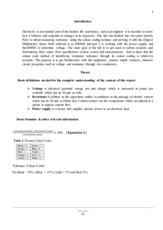
Theory
Basic definitions needed for the complete understanding of the content of this report:
Voltage is electrical potential energy per unit charge which is measured in joules per
coulomb which has its SI unit as volts.
Resistance is defined as the opposition within a conductor to the passage of electric current
which has its SI unit as Ohms (Ω). Carbon resistor are the components which are placed in a
circuit to oppose current flow.
Power supply is a device that supplies electric power to an electrical load.
Basic formulas & other relevant information
퐶푙푎푐푢푙푎푡푒푑 푣푎푙푢푒 −푀푒푎푠푢푟푒푑 푣푎푙푢푒
퐶푎푙푐푢푙푎푡푒푑 푣푎푙푢푒
× 100 (푬풒풖풂풕풊풐풏 ퟏ)
Tolerance Colour Codes
No Band = 20%; Silver = 10 %; Gold = 5% and Red=2%.
2. 2
Pre-Lab
Question 1:
a) R= (Brown, Black)×10red
R= 10×102= 1000Ω
Tolerance= Silver= 10%
10
100
× 1000 = 100Ω
Therefore this resistor has a value tolerance between 900Ω and1100Ω
b) R= (Red, Green, Black) ×10brown
R= 250×101= 2500Ω
Tolerance= Red = 2%
12
100
× 2500 = 50Ω
Therefore this resistor has a value tolerance between 2450Ω and 2550Ω
b) R= (Brown, Black)*10blue
R= 10×106=10MΩ
Tolerance= Gold= 5%
5
100
× 10000000 = 500000 Ω =0.5 MΩ
Therefore this resistor has a value between 9.5MΩ and 10.5MΩ
Question 2:
a) 1.75 kΩ ±2%
1.75×1000= 1750 Ω
According to the Colour codes 1=brown, 7= violet, 5=green, brown= 2 and red is 2%
The colour code is {Brown, Violet, Green, Brown, and Red}
b) 10MΩ ±5%
10×106= 10000000 Ω
According to the colour codes 1= brown, 0= black, 6= blue and gold is 5%
The colour code is {Brown, Black, Blue, and Gold}
3. 3
c) 38kΩ ±5%
38×1000= 38000
According to the Colour codes 3= orange, 8= grey, 3= orange and gold is 5%
The Colour code is {Orange, Grey, Orange, and Gold}
Equipment used
Power supply
Digital Multimeter (DMM) which serves as a Voltmeter and Ammeter
Three carbon resistors with different resistances
Two conductors
Procedures
To Measure Voltage:
Change the voltage selection knob on the DMM to (DC or –V) for DC measurement. Voltage is
measured in parallel with the load and the range of your measurement can be altered by using the
Range buttons.
To Measure Current:
Change the current outlet of the DMM to (“+” terminal) and the COM outlet (ground). Current is
measured in series you will have to break the circuit to measure current. For a current less than
200mA use the outlet (VΩA) and for current greater than 200mA use the outlet written 20A
in red else the DMM will not be accurate and may not show the current reading. You can vary the
range of your measurement by using the Range buttons.
To Measure Power Supply Voltage:
A voltmeter is always connected in parallel across your load or power supply. The “+” terminal of
the voltmeter should be connected to the “+” terminal of the Power Supply hence forth referred to
as (PS) (usually the red outlet) and the “-” terminal of the voltmeter to the “-” terminal of the PS
(usually the COM or black outlet) of the DMM.
Part 1 of the lab
1. Push the power button to turn on the multi-meter.
2. To use the DMM as an ohmmeter, turn the knob so that it points on the side of resistance,
where there is (Ω) symbol.
3. Get three resistors from your toolbox.
4. 4
4. From the colour code of each resistor, determine the resistance and the tolerance of each
resistor.
5. Calculate the range of resistance values for each resistor based on the tolerance of the
resistors.
6. These results were recorded on the table provided.
7. Using the DMM, measure the resistance of each resistor.
8. To do this try to seek advice from the laboratory assistant (insert a red banana-to-clip
connector into the Ω-plug and a black banana clip connector into the COM-plug). Place the
resistor-under-test between the red and the black connectors.
9. Record this on the table provided.
Part 2 of the lab
1. Set the Meter knob of the PS to the +5 V position, and connect the two wires from the PS (+
V and COM outlets) to the voltmeter.
2. Since you’re measuring DC voltage, press the --V button and maximum range on your
Multimeter.
3. Adjust the output of the PS by using the Voltage +5 V knob.
4. Check your voltage by reading the volts scale of your PS (lower reading) and compare it to
the voltmeter reading.
Results
Part 1 results: Measuring Resistance
Exercise
Calculations using Equation (1) % Error
R1=
560 −570
560
× 100 = -1.79%
R2= 27−27.2
27
× 100 = -0.74%
R3=
47−46 .9
47
× 100 = 0.2%
Table 1
Resistor Colour Codes Value of resistance
calculated from colour code
Measured value
or resistance
% Error
R1 Green, Blue, Brown, Gold 560Ω ±5% 570Ω -1.79%
R2 Red, Violet, Black, Gold 27Ω ±5% 27.2Ω -0.74%
R3 Yellow, Violet, Black,
Gold
47Ω ±5% 46.9Ω 0.2%
5. 5
Table 2
Part 2: Use of Power Supply
Exercise
Readings from Power Supply and Voltmeter respectively…
Power Supply Voltmeter
5V 5.05V
10V 9.96V
15V 15.03V
20V 19.9V
25V 24.9V
30V 29.8V
Table 3
Discussions
Part 1:
Tolerance for all the resistors is more or less 5%. The negative percentages just mean that the amount
that we have calculated has been exceeded by that percentage, and the positive percentages just mean
that the amount that we have calculated has not been exceeded by that percentage. All the errors for
each resistance measured fall within the calculated ranges. Therefore the method of calculat ing
resistance ranges using colour codes is approximately accurate and can be used as an alternative to
measuring the resistances all the time.
Part 2:
The reason why the voltmeter readings are slightly lower or bigger is because the power supply has
an internal resistance. Within the conductors energy is converted into other forms of energy such as
(heat) causing the voltage drop. This affects the potential difference as proven above with table
number 3.
Conclusion:
In conclusion I have learned how to operate the DMM and that making the use of colour codes to
calculate the resistance of a resistor is faster than actually measuring that resistance. The errors due
to these calculations is very small and is within the range of resistivity of the resistor. There is also
the matter of the conversion of electricity from one form to another that I have noticed while doing
the last exercise in which the voltage readings are quite different from the real ones. This is due to
6. 6
the elements that contribute to the resistance namely (length of conductor, material of conductor,
cross sectional area of the conductor and the material from which the conductor is made from).
Furthermore I think that these findings were useful in the sense that I now understand more about
electrical circuits than before these lab and that it will contribute to the foundation of my engineer ing
career.