Download to read offline
![International Journal of Engineering Research and Development
e-ISSN: 2278-067X, p-ISSN: 2278-800X, www.ijerd.com
Volume 8, Issue 2 (August 2013), PP. 93-98
93
Modeling of Wind Driven Induction Generator for
Constant Power Applications Using Matlab
N. Sravanthi1
, K. Sudarshan Reddy2
,
P.G. Student, Svpcet, Puttur1
Faculty, Svpcet Puttur2
Abstract:- In this project a modular simulink Implementation of an Induction generator is described in step-step
approach.with the modular system each block solves one of the model equations.This particularly for highly
wind generated areas and Induction generator with inverter system creates a hybrid system.This hybrid system
inherently adapts to the changes in rotor speed or load on the generator while maintaining the constant voltage at
load terminals.
I. INTRODUCTION
Owing to the increased emphasis on the global energy crisis and environmental pollution, deployment
of clean and renewable energy sources such as wind or solar for power generation has assumed vital importance.
In a stand-alone wind power generation system with a self-excited induction generator, it is necessary to provide
a dynamically variable reactive power to maintain a constant output voltage. Several studies on induction
generators for stand-alone applications have been reported in literature. In some of the schemes, only the voltage
magnitude is controllable but the frequency is not controllable, depending largely on the speed. Although in the
frequency control was achieved through regulation of externally applied mechanical torque, the aspect of
frequency control was obviated by feeding only dc loads in . Most of these schemes use complex control
strategies implemented essentially in closed loop. Thyristor or GTO thyristor-based reactive power
compensation schemes emulating variable reactive impedance were used to regulate the generator terminal
voltage. Poor dynamic response, harmonic currents, bulky reactor associated with magnetic saturation and
losses were the drawbacks of these schemes. In order to improve the performance of the system, use of modern
control techniques such as direct and indirect vector control have been suggested .
Although the use of vector control technique improves the performance of the system, the overall
system becomes complex with a number of sensors and intricate signal processing.
Constant voltage and constant frequency operation of a stand-alone induction generator is reported in
[8–12]. A dual winding induction generator was employed with an inverter feeding the control winding , while
in a normal induction machine with control based on instantaneous reactive power theory and synchronising
signal templates were investigated, in generalised impedance controller is used to regulate the voltage and
frequency of the stand-alone induction generator. The frequency control of generator output was not considered
in an ac - dc power interface system where the generator output voltage is rectified and regulated to feed only
dc loads. To feed ac loads, the scheme requires additional inverter. The excitation controller composed of an ac
power capacitor and a power converter connected in series.
Control of generator voltage and frequency while feeding balanced/unbalanced linear and non-linear
loads is reported in using composite controller with storage battery and also in where three single-phase voltage
source converters (VSCs) with a common dc link are employed. Simulation results are presented for the analysis
in both the schemes. In the scheme reported by Jayaramaiah and Fernandes the generator output voltage is non-
sinusoidal and the frequency is not constant. In , voltage and frequency control is achieved using a PWM
voltage source converter with a capacitor and a chopper on the dc side. For achieving power balance, controlled
ac (dump) loading was preferred over controlled dc load. However, the phase angle control of the controlled ac
load leads to domination of harmonic currents in the system, especially when generator power is greater than the
uncontrolled load. The scheme employs dc voltage regulation by sensing the dc link voltage as the feedback
parameter.
This paper proposes a hybrid exciter that is essentially a sensor-less, open-loop reactive power
compensator. The open-loop compensator inherently adapts to the changes in the rotor speed or load on the
generator although it maintains a near constant voltage and constant frequency at the generator output terminals.
The test system consists of a laboratory prototype induction machine coupled to a dc motor functioning as the
prime mover (wind turbine). The firing pulses for the insulated gate bipolar transistors (IGBTs) in the fixed
frequency PWM inverter are produced using a microcontroller. The PWM inverter is operated in an open loop,
without the need for any sensor other than the low-speed and high-speed cut-out mechanism on the wind
turbine.](https://image.slidesharecdn.com/l08029398-130815042915-phpapp02/85/International-Journal-of-Engineering-Research-and-Development-IJERD-1-320.jpg)
![International Journal of Engineering Research and Development
e-ISSN: 2278-067X, p-ISSN: 2278-800X, www.ijerd.com
Volume 8, Issue 2 (August 2013), PP. 93-98
93
Modeling of Wind Driven Induction Generator for
Constant Power Applications Using Matlab
N. Sravanthi1
, K. Sudarshan Reddy2
,
P.G. Student, Svpcet, Puttur1
Faculty, Svpcet Puttur2
Abstract:- In this project a modular simulink Implementation of an Induction generator is described in step-step
approach.with the modular system each block solves one of the model equations.This particularly for highly
wind generated areas and Induction generator with inverter system creates a hybrid system.This hybrid system
inherently adapts to the changes in rotor speed or load on the generator while maintaining the constant voltage at
load terminals.
I. INTRODUCTION
Owing to the increased emphasis on the global energy crisis and environmental pollution, deployment
of clean and renewable energy sources such as wind or solar for power generation has assumed vital importance.
In a stand-alone wind power generation system with a self-excited induction generator, it is necessary to provide
a dynamically variable reactive power to maintain a constant output voltage. Several studies on induction
generators for stand-alone applications have been reported in literature. In some of the schemes, only the voltage
magnitude is controllable but the frequency is not controllable, depending largely on the speed. Although in the
frequency control was achieved through regulation of externally applied mechanical torque, the aspect of
frequency control was obviated by feeding only dc loads in . Most of these schemes use complex control
strategies implemented essentially in closed loop. Thyristor or GTO thyristor-based reactive power
compensation schemes emulating variable reactive impedance were used to regulate the generator terminal
voltage. Poor dynamic response, harmonic currents, bulky reactor associated with magnetic saturation and
losses were the drawbacks of these schemes. In order to improve the performance of the system, use of modern
control techniques such as direct and indirect vector control have been suggested .
Although the use of vector control technique improves the performance of the system, the overall
system becomes complex with a number of sensors and intricate signal processing.
Constant voltage and constant frequency operation of a stand-alone induction generator is reported in
[8–12]. A dual winding induction generator was employed with an inverter feeding the control winding , while
in a normal induction machine with control based on instantaneous reactive power theory and synchronising
signal templates were investigated, in generalised impedance controller is used to regulate the voltage and
frequency of the stand-alone induction generator. The frequency control of generator output was not considered
in an ac - dc power interface system where the generator output voltage is rectified and regulated to feed only
dc loads. To feed ac loads, the scheme requires additional inverter. The excitation controller composed of an ac
power capacitor and a power converter connected in series.
Control of generator voltage and frequency while feeding balanced/unbalanced linear and non-linear
loads is reported in using composite controller with storage battery and also in where three single-phase voltage
source converters (VSCs) with a common dc link are employed. Simulation results are presented for the analysis
in both the schemes. In the scheme reported by Jayaramaiah and Fernandes the generator output voltage is non-
sinusoidal and the frequency is not constant. In , voltage and frequency control is achieved using a PWM
voltage source converter with a capacitor and a chopper on the dc side. For achieving power balance, controlled
ac (dump) loading was preferred over controlled dc load. However, the phase angle control of the controlled ac
load leads to domination of harmonic currents in the system, especially when generator power is greater than the
uncontrolled load. The scheme employs dc voltage regulation by sensing the dc link voltage as the feedback
parameter.
This paper proposes a hybrid exciter that is essentially a sensor-less, open-loop reactive power
compensator. The open-loop compensator inherently adapts to the changes in the rotor speed or load on the
generator although it maintains a near constant voltage and constant frequency at the generator output terminals.
The test system consists of a laboratory prototype induction machine coupled to a dc motor functioning as the
prime mover (wind turbine). The firing pulses for the insulated gate bipolar transistors (IGBTs) in the fixed
frequency PWM inverter are produced using a microcontroller. The PWM inverter is operated in an open loop,
without the need for any sensor other than the low-speed and high-speed cut-out mechanism on the wind
turbine.](https://image.slidesharecdn.com/l08029398-130815042915-phpapp02/75/International-Journal-of-Engineering-Research-and-Development-IJERD-1-2048.jpg)
![Modeling of Wind Driven Induction Generator for Constant Power…
95
inverter. The dc bus of the inverter is supported by a battery and the inverter is operated at a fixed frequency
suitable for the induction machine.
(a) Mathematical model of the induction machine
The dynamic equations governing the stator and the rotor
currents in the stator flux coordinates can be written as follows [20, 21]:
Fig. 2. Equivalent circuit of system
a) d-axis model
b) q-axis system model
(b) Modeling of excitation system
(i) Capacitor: The state equations of fixed capacitor bank are derived using the d – q components of stator
voltage as state variables from the circuit shown in Fig. 2.
(ii) Inverter – battery system: Using the d – q components of inverter current as state variables the following
differential equations are derived from the circuit shown in Fig. 2.
(c) Resistive load: The d– q axes current equations for the balanced resistive load can be given by](https://image.slidesharecdn.com/l08029398-130815042915-phpapp02/85/International-Journal-of-Engineering-Research-and-Development-IJERD-3-320.jpg)
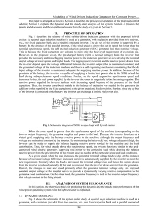
![Modeling of Wind Driven Induction Generator for Constant Power…
97
Fig.4.4. Stator current of the induction generator
2 2.5 3 3.5
x 10
4
-600
-400
-200
0
200
400
600
LoadVoltage(Volts)
Time(sec)
Load
Voltage(Volts)
4.5 .Load voltage
V. CONCLUSION AND FUTURE WORK
The standalone operation of induction generator is discussed in detail. The SEIG is connected to the
VSI and battery energy storage system. The reactive power to the generator is supplied by the capacitor bank
and the VSI. The mathematical modeling of overall inter connection is modeled using the basic mathematical
equations.
If the input (wind velocity for the wind turbine) to the generator is low the generator output will be low.
If the generated output is less than the connected load the battery will supply the power to the load. If the load is
inductive the reactive power is supplied by the voltage source inverter to reach the requirement.
Thus the above discussed system can be used in remote locations where the transmission system is not
economical. So the stand alone application of SEIG gained importance in modern usage.
Future work is to implement same proposed scheme along with boost converter and PV panel.
REFERENCES
[1] A. Karthikeyan C. Nagamani G. Saravana Ilango A. Sreenivasulu Hybrid, open-loop excitation system
for a wind turbine-driven stand-alone induction generator “International conference on power
Electronics Vol.No.99,April2011”
[2] S. Wade, M. W. Dunnigan, B. W. Williams, “Modeling and simulation of induction machine vector
control with rotor resistance identification,” IEEE Transactions on Power Electronics, vol. 12, no .3,
May 1997, pp. 495 -506
[3] B. Ozpineci, B.K. Bose, "A soft-switched performance enhanced high frequency non-resonant link
phase-controlled converter for ac motor drive," The 24th Annual Conference of the IEEE Industrial
Electronics Society (IECON'98), Aachen/Germany, 1998, vol. 2, pp 733-749
[4] H. Le-Huy, “Modeling and simulation of electrical drives using Matlab/Simulink and Power System
Blockset,” The 27th Annual Conference of the IEEE Industrial Electronics Society (IECON'01),
Denver/Colorado, pp. 1603-1611.
[5] Y. Kang and J.D. Lavers, “Transient Analysis of Electric Power Systems: Formulation and Theoretical
Basis,”IEEE Transactions on Power Systems, Vol. 11, No. 2, pp.754-760, May 1996
[6] N. Mohan, W.P. Robbins, L.A. Aga, M. Rastogi, and R. Naik, “Simulation of Power Electronics and
Motion Control Systems,” chapter 8 in Power Electronics and Variable Frequency Drives, Edited by
B.K. Bose, IEEE Press, New York 1997, pp. 400-453](https://image.slidesharecdn.com/l08029398-130815042915-phpapp02/85/International-Journal-of-Engineering-Research-and-Development-IJERD-5-320.jpg)
![Modeling of Wind Driven Induction Generator for Constant Power…
98
[7] M.F. Rahman, L. Bong and K. W. Lim," A direct torque controlled interior magnet synchronous motor
drive incorporating field weakening", 'I Industrial Applications, IEEE Transactions on, Vol. 34 No. 6
pp. 1246-1253, Nov./Dec. 1998
[8] lsao Takahashi and Ohmori, Y." High-performance direct torque control of an Induction motor"
Industrial Applications, IEEE Transactions on, Volume 25 Issue 2 March-April 1989
[9] Hegde, R.K.: „A wind driven self excited induction generator with terminal voltage controller and
protection circuits‟IEEE Int Conf.on Power Conversion April 99.
[10] Bhim, S., Gaurav kumar, K.: „Solid state voltage and frequency controller for a stand alone wind power
generating system‟, IEEE Trans. Power Electron., 2008, 23, (3), pp. 1170–1177
[11] Venkatesa Perumal, B., Jayanta, K.: „Voltage and frequency control of a stand alone brushless wind
electric generation using generalized impedance controller‟, IEEE Trans. Energy Convers., 2008, 23,
(2), pp. 632–641.
[12] Singh, B., Murthy, S.S., Gupta, S.: „STATCOM-based voltage Regulator for self-excited induction
generator feeding nonlinear loads‟, IEEE Trans. Ind. Electron., 2006, 53, (5), pp. 1437–1452.
[13] Wu, J.-C.: „AC/DC power conversion interface for self-excited Induction generator‟, IET Renew.
Power Gener., 2009, 3, (2), pp. 144– 151.
[14] Barrado, J.A., Robert, G., Hugo, V.: „Standalone self-excited induction generator with a three-phase
four-wire active filter and energy storage system‟. IEEE Int. Symp. on Industrial Electronics, June
2007, pp. 600–605.
[15] Bhim, S., Gaurav Kumar, K.: „Voltage and frequency controller for three-phase four-wire
autonomous wind energy conversion system‟, IEEE Trans. Energy Convers., 2008, 23, (2), pp.
509 –518.
[16] Jayaramaiah, G.V., Fernandes, B.G.: „Novel voltage controller for stand- alone induction generator
using PWM-VSI‟. IEEE Int. Conf. on Industry Applications, October 2006, vol. 1, pp. 204– 208.
[17] Marra, E.G., Pomilio, J.A.: „Self-excited induction generator controlled by a VS-PWM bidirectional
converter for rural applications‟, IEEE Trans. Ind. Appl., 1999, 35, (4), pp. 877– 883.
K.Sudharsan Reddy He received his B.Tech (Electrical and Electronics
Engineering) degree from JNTU,Hyderabad, at S.J.C.E.T, M.Tech (PE) from JNTU,
Anantapur, at R.G.M.C.E.T, Nandyal.He is currently working as Assistant Professor ,
Electrical and Electronic Engineering, S.V.P.C.E.T,Puttur.
N.Sravanthi She received her B.Tech (Electrical and Electronics Engineering)
degree from JNTU,Anantapur at S.V.P.C.E.T, Puttur, M.Tech (PE&ED)) from
JNTU, Anantapur at S.V.P.C.E.T, Puttur.](https://image.slidesharecdn.com/l08029398-130815042915-phpapp02/85/International-Journal-of-Engineering-Research-and-Development-IJERD-6-320.jpg)

The document presents a modular Simulink implementation of a wind-driven induction generator designed for constant power applications, emphasizing the need for renewable energy sources like wind power amid the global energy crisis. It describes a hybrid system utilizing a self-excited induction generator with an inverter, which adapts to changes in rotor speed and load while maintaining constant voltage at the output terminals. The paper details the theoretical and dynamic analysis, simulation results, and proposes a sensor-less, open-loop reactive power compensator for enhancing the performance of the generator system.