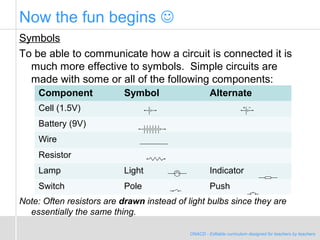
ONACD - Editable curriculum designed for teachers by teachers
Simple Circuits
Symbols and Devices
ONACD –Editable Curriculum designed for teachers by teachers
A vacuum salesman appeared at the door of an old lady's cottage
and, without allowing the woman to speak, rushed into the living
room and threw a large bag of dirt all over her clean carpet. He
said, "If this new vacuum doesn't pick up every bit of dirt then I'll
eat all the dirt."
The woman, who by this time was losing her patience, said, "Sir, if
I had enough money to buy that thing, I would have paid my
electricity bill before they cut it off. Now, what would you prefer, a
spoon or a knife and fork?"
ONACD - Editable curriculum designed for teachers by teachers
Now the fun begins 
Symbols
To be able to communicate how a circuit is connected it is
much more effective to symbols. Simple circuits are
made with some or all of the following components:
Note: Often resistors are drawn instead of light bulbs since they are
essentially the same thing.
Component Symbol Alternate
Cell (1.5V)
Battery (9V)
Wire
Resistor
Lamp Light Indicator
Switch Pole Push
ONACD - Editable curriculum designed for teachers by teachers
More fun
Since we can calculate resistance (R) we only need to be
able to measure voltage (V) and current (I). To measure
voltage we use a Voltmeter. To measure current we use
an Ammeter.
Aside: A meter is a device for measuring. A metre is a unit of length.
So a “metre meter” is a stick that measures the unit length of distance.
Component Symbol
Voltmeter
Ammeter
ONACD - Editable curriculum designed for teachers by teachers
Consider the following simple circuit with a 1.5 V dry cell and a
light bulb (or resistor).
How should an Ammeter be connected to measure current
going into the resistor?
In order to measure current the device has to actually be part
of the circuit. Think back to the analogy of water flow. The
current is based on flowing charge.
Note: it doesn’t matter where in the circuit as the current will be the same.
ONACD - Editable curriculum designed for teachers by teachers
How should a Voltmeter be connected to measure
voltage across the resistor?
In order to measure the voltage the device compares the
difference between two points on the circuit. So the
voltmeter connects at each end of the resistor to
measure the amount of electric attraction from one end
of the resistor to the other.

L08 c7 - notes - teacher master - simple circuits - pp

  • 1.
    ONACD - Editablecurriculum designed for teachers by teachers Simple Circuits Symbols and Devices ONACD –Editable Curriculum designed for teachers by teachers A vacuum salesman appeared at the door of an old lady's cottage and, without allowing the woman to speak, rushed into the living room and threw a large bag of dirt all over her clean carpet. He said, "If this new vacuum doesn't pick up every bit of dirt then I'll eat all the dirt." The woman, who by this time was losing her patience, said, "Sir, if I had enough money to buy that thing, I would have paid my electricity bill before they cut it off. Now, what would you prefer, a spoon or a knife and fork?"
  • 2.
    ONACD - Editablecurriculum designed for teachers by teachers Now the fun begins  Symbols To be able to communicate how a circuit is connected it is much more effective to symbols. Simple circuits are made with some or all of the following components: Note: Often resistors are drawn instead of light bulbs since they are essentially the same thing. Component Symbol Alternate Cell (1.5V) Battery (9V) Wire Resistor Lamp Light Indicator Switch Pole Push
  • 3.
    ONACD - Editablecurriculum designed for teachers by teachers More fun Since we can calculate resistance (R) we only need to be able to measure voltage (V) and current (I). To measure voltage we use a Voltmeter. To measure current we use an Ammeter. Aside: A meter is a device for measuring. A metre is a unit of length. So a “metre meter” is a stick that measures the unit length of distance. Component Symbol Voltmeter Ammeter
  • 4.
    ONACD - Editablecurriculum designed for teachers by teachers Consider the following simple circuit with a 1.5 V dry cell and a light bulb (or resistor). How should an Ammeter be connected to measure current going into the resistor? In order to measure current the device has to actually be part of the circuit. Think back to the analogy of water flow. The current is based on flowing charge. Note: it doesn’t matter where in the circuit as the current will be the same.
  • 5.
    ONACD - Editablecurriculum designed for teachers by teachers How should a Voltmeter be connected to measure voltage across the resistor? In order to measure the voltage the device compares the difference between two points on the circuit. So the voltmeter connects at each end of the resistor to measure the amount of electric attraction from one end of the resistor to the other.
  • 6.
    ONACD - Editablecurriculum designed for teachers by teachers How should a Voltmeter be connected to measure voltage across the resistor? In order to measure the voltage the device compares the difference between two points on the circuit. So the voltmeter connects at each end of the resistor to measure the amount of electric attraction from one end of the resistor to the other.