Kikusui ac power_supply_pcr-le_le2
•
0 likes•8 views

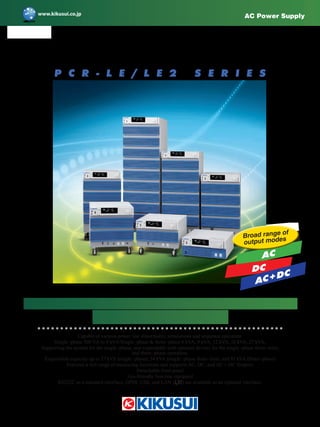
The PCR-LE2 Series are designed based on the PCR-LE Series that supports single-phase output, single-phase 3-wire output, and three-phase output within the rated capacity by selecting the switch from the front panel operation. The PCR-LE2 series offer the same basic performance, using the common power unit of the PCR-LE Series, with providing easier installation and saving the space more efficiently compare to the individual allocation of the system for a single phase, single-phase 3-wire, and three phase systems. The lineup of PCR-LE2 Series are available in 5 models:6 kVA, 9 kVA, 12kVA, 18kVA, and 27 kVA model.

Recommended
Recommended
More Related Content
What's hot
What's hot (20)
Similar to Kikusui ac power_supply_pcr-le_le2
Similar to Kikusui ac power_supply_pcr-le_le2 (20)
More from NIHON DENKEI SINGAPORE
More from NIHON DENKEI SINGAPORE (20)
Recently uploaded
Recently uploaded (20)
Kikusui ac power_supply_pcr-le_le2
- 1. Capable of various power line abnormality simulations and sequence operation. Single–phase 500 VA to 9 kVA/Single–phase & three–phase 6 kVA, 9 kVA, 12 kVA, 18 kVA, 27 kVA, Supporting the system for the single–phase, and expandable with optional drivers for the single–phase three–wire, and three–phase operation. Expandable capacity up to 27 kVA (single–phase), 54 kVA (single–phase three–line), and 81 kVA (three–phase) Features a full range of measuring functions and supports AC, DC, and AC + DC Outputs Detachable front panel Eco-friendly function equipped RS232C as a standard interface, GPIB, USB, and LAN ( ) are available as an optional interface. High-performance multifunctional AC Power Supplies PCR-LE/LE2 Series AC Power Supply P C R - L E / L E 2 S E R I E S AC Broad range of output modes DC AC+DC
- 3. AC Power Supply PCR-LE series 3
- 4. 4 The PCR-LE Series is a new line of advanced multifunctional AC power supply that has been developed from our PCR-L/LA Series (linear amplifier type). The PCR-LE Series provides high reliability and can be applied to various applications, by taking advantage of the features that can control broadband waveform freely. Moreover, the PCR- LE Series can be configured as a core device of a test system combined with E-loads and Power Analyzers for “Grid Connection Testing” in regard to dispersed power generation, such as Solar Power, Wind Power, Fuel Cell, and Gas Engine referred to as “New Energy Field”. With various options, the low frequency immunity test and various power enviroment tests are supported. The options for parallel operation and three-phase operation enable you to expand a single-phase system up-to 27 kVA, single-phase three wires up-to 54 kVA, and a three- phase system up to 81 kVA. The system can be applied to a large-scale EMC site for testing of industrial high-capacity air conditioners. New stage of AC power supply supporting new energy field 6 kVA 9 kVA [Applications] ▼ Research & Development Proof evaluation for power supply abnormality, EMC testing ▼ Adjustment & Inspection Lines Power supply voltage margin check, Automated inspection system ▼ Production Lines For stabilizing the line power supply, Automated testing system ▼ Quality Assurance IE ard Testing ▼ After-Sales Service As power supply for repair and calibration To reproduce power line abnormalities High-performance AC Power Supplies PCR-LE SERIES
- 5. AC Power Supply PCR-LE series 5 ● Lineup Model PCR500LE PCR1000LE PCR2000LE PCR3000LE PCR4000LE PCR6000LE PCR9000LE Output capacity Single-phase 500 VA Single-phase 1 kVA Single-phase 2 kVA Single-phase 3 kVA Single-phase 4 kVA Single-phase 6 kVA Single-phase 9 kVA Maximum output current 5 A / 2.5 A 10 A / 5 A 20 A / 10 A 30 A / 15 A 40 A / 20 A 60 A / 30 A 90 A / 45 A AC mode (L/H range) 1 V to 150 V / 2 V to 300 V 5 A / 2.5 A 10 A / 5 A 20 A / 10 A 30 A / 15 A 40 A / 20 A 60 A / 30 A 90 A / 45 A DC mode (L/H range) ±1.4 V to ±212 V / ±2.8 V to ±424 V 3.5 A / 1.75 A 7 A / 3.5 A 14 A / 7 A 21 A / 10.5 A 28 A / 14 A 42 A / 21 A 63 A / 31.5 A Dimensions (mm(inches)) (Maximum dimensions) 430 (16.93") W 430 (16.93") W 430 (16.93") W 430 (16.93") (445 (17.52")) W 430 (16.93") (445 (17.52")) W 430 (16.93") (445 (17.52")) W 430 (16.93") (445 (17.52")) W 173 (6.81") (195 (7.68")) H 262 (10.31") (345 (13.58")) H 389 (15.31") (475 (18.70")) H 690 (27.17") (785 (30.91")) H 690 (27.17") (785 (30.91")) H 944 (36.17") (1040 (40.94")) H 1325 (52.17") (1420 (55.91")) H 550 (21.65") (600 (23.62")) D 550 (21.65") (595 (23.43")) D 550 (21.65") (595 (23.43")) D 550 (21.65") (595 (23.43")) D 550 (21.65") (595 (23.43")) D 550 (21.65") (595 (23.43")) D 550 (21.65") (595 (23.43")) D Weight Approx. 17 kg (37.4 lbs) Approx. 35 kg (77.1 lbs) Approx. 55 kg (121.2 lbs) Approx. 82 kg (180.7 lbs) Approx. 96 kg (211.6 lbs) Approx. 140 kg (308.6 lbs) Approx. 190 kg (418.8 lbs) Appearance 500 VA 1 kVA 2 kVA 4 kVA 3 kVA
- 6. R&D Production Inspection QA Service Service R&D Inspection Production Service Service QA Production Inspection R&D Service R&D Safety Satisfy Reliability 6 Mode Category Tested device Test contents Refer to page AC Product tests Home electronics, office equipment, industrial equipment Power fluctuation tests 12 to 14 IEC61000 standard low-frequency immunity tests Reproduction and evaluation of voltage abnormalities in the market Component tests Power conditioners Power regeneration tests 12 to 13 AC/DC converters Power fluctuation tests AC + DC DC Component tests DC/DC converters Tests of conversion from high voltage to low voltage Simulations of voltage fluctuations in EV and HEV high-voltage batteries 14 Capacitors Ripple current tests of high-voltage capacitors AC,AC + DC,DC Component tests EV charging systems Tests of requirements for IEC61851 and ECE R10.04 standards advantage List by PCR-LE applications The linear amplifier type realizes high stability and high quality output and supports a wide range of functions from R&D to manufacturing/inspection lines and servicing. What is a PWM inverter? This type uses a PWM (Pulse Width Modulation) switching-type DC/ AC inverter which is placed as a part instead of the linear amplifier. Because this is a switching type, it cannot provide feedback over a wide range while the linear amplifier can. As a result, the output quality and response gets inferior, and noise becomes larger, compared to the linear amplifier type. However it has the advantages of being smaller and more efficient than the linear amplifier type, and is also pulling attention as a high- performance AC power supply for energy-saving purposes. What is a linear amplifier type? Firstly, the input power is converted to DC power by a rectifier circuit, then it supplies the power as the linear amplifier. A sine wave reference voltage is created by such a crystal oscillator, and it is used as input into the linear amplifier, where the power amplification is performed to generate the output power. In addition to its high-speed response characteristics, because the output voltage and frequency can be changed whenever necessary, this system can be used to conduct simulations of power line abnormalities (such as instantaneous power interruption tests), and also it can be applied to the testing of ATE and other purposes.
- 7. AC Power Supply PCR-LE series 7 ● Evaluation for the immunity of power abnormalities. ● Capable of DC output. ● Easily conducting power measurement. ● Can be used in anechoic chambers and shield rooms. The PCR-LE Series has equipped with the measurement functions built into the main unit, it can be used not only for voltage and cur- rent measurement, but also for convenient measurement of appar- ent and effective power, inrush (peak) current, power factor, high- frequency current, and other values. Furthermore,it is capable to conduct such as power line abnormality simulations, sequencing functions, and arbitrary waveform generation also provide a dramat- ic improvement in data reproducibility and reliability when evaluating immunity to instantaneous power interruptions, voltage fluctuations, frequency fluctuations, missing phase, and other power line abnormali- ties. In addition, the PCR-LE has maximum DC output of ±424 V. This is extremely convenient when a slight DC output is required in case driving a DC/DC converter. The PCR-LE Series can also be used as AC power sources in various EMC test sites (anechoic chambers, shield rooms, etc.). * Use of the arbitrary waveform generation function and other functions requires separate application software SD011-PCR-LE (Wavy for PCR-LE). ● To confirm the power voltage margin. ● Use in automated inspection systems. The PCR-LE Series can be used for operation checks of the power voltage range, and as a power supply for aging. Multiple units of the PCR-LE Series can be connected in parallel to boost capacity, and can also be connected in 3 phases, allowing flexible adaptation to line changes or the number of aging units. Remote control and monitoring from a PC is also supported using the GPIB or RS-232C communication or USB or LAN interface, and it can be used for management of inspection records and other quality data as well. * The GPIB, USB, and LAN are available as an interface option. ● Use as a standard room power supply. ● Conducting of IEC standard tests. The PCR-LE Series can be used as a power supply in standard rooms and measurement device management rooms. ● Use as a power supply for repairs and calibration. ● Reproduction of power abnormalities. The PCR-LE Series can also make a large contribution to repairs, inspections, calibration, and other servicing work. For example, the PCR500LE (output capacity 500 VA) allows worldwide commercial power (100 V - 240 V) to be supplied from a household electrical outlet (100 V, 15 A). This is highly recommended for servicing sites where large equipment cannot be installed and it also can be used for the field service. Since the PCR-LE Series can supply clean power that is free of fluctuation or distortion for inspection and cali- bration work, it can help to maintain and improve quality of service. ● Use as a CVCF power supply. ● Stabilization of the power line. With the PCR-LE Series, it can be used as a CVCF power supply to handle worldwide commercial power (100 V - 240 V), as well as for marine and aircraft power (400 Hz). It can supply a maximum out- put peak current up to 4 times the rating (rms) with a capacitor input load (both peak value and continuous supply), or approximately 2 times the rating (rms) for motors and other loads with large in-rush currents (peak value, approximately 10 seconds*, when power fac- tor is 1). The PCR-LE Series is also recommended for power sta- bilization when using precision machining systems, measurement systems, and others where the voltage abnormalities becomes an issue. With an output voltage response speed of 30 μs (standard value) and a waveform distortion factor of 0.3 % or less, the PCR- LE Series provides extremely high speed and high quality that are particularly effective with systems such as welders and semicon- ductor manufacturing equipment where even slight power fluctua- tions or load fluctuations can affect quality and accuracy. *Output shuts off after 10 seconds. Waveform distortion occurs if the current exceeds the rating anytime during the period of 10 seconds. ■ For R&D: ■ For Adjustment and Inspection lines: ■ For Quality Assurance: ■ For Manufacturing lines: ■ For After-sales service:
- 8. 8 ■ Parallel operation *The separately-sold expansion operation driver is required. Can be expanded to 54 kVA (single phase 3-wire) or 81 kVA (three phase) when used in combination with the single phase 3-wire option or three phase option. ★ Combinations of different models are possible! Example: PCR2000LE + PCR4000LE + PCR6000LE = Single phase 12 kVA ■ Single phase 3-wire, three phase operation * The separately-sold expansion operation driver is required. All models / Max. expanded capacity: 54 kVA (single phase 3-wire), 81 kVA (three phase) When used in combination with the parallel operation option ★ Combinations of different models are possible! Example:PCR2000LE + PCR2000LE + PCR4000LE = 6kVA "Three-phase" or 8kVA "Unbalanced Three-phase" features It is possible to expand to 27 kVA (single phase), 54 kVA (single phase 3-wire), and 81 kVA (three phase) by using the parallel, single phase 3-wire, and three phase operation options (expansion operation drivers). This allows the system to be used for large-scale EMC site power or as test power for large-capacity industrial air conditioners. Conforming to the guideline of the Japanese standard requirements of system interconnection technologies 2kVA 4kVA 6kVA 12 kVA Single phase + + 2kVA 2kVA 4kVA 6 kVA * Three phases + + *8kVA when used in the "Unbalanced Three-phase" AC Power supply PCR-LE Series HarmonicAnalyzer KHA3000 AC Power supply PAT-T Series etc Power conditioner LCR Load 0- V POWER POWER POWER MEMORY F1 F1 F2 F2 F3 F3 F4 F4 F5 F5 F6 F6 KHA3000 HARMO NIC /FLICKER A NALYZER REMOTE USB BACKLIGHT FILE HARDCOPY STOP START HA Vf OTHER EXTCONT 9 6 1 2 3 0 . - ESC ENTER ASSIST SYSTEM REMOTE KEYLOCK UTILITY GPIB MODE VIEW HOLD SHIFT ENTRY V RANGE V RANGE I RANGE I RANGE 7 8 4 5 BUZZER BUZZER LOCAL Oscilloscope Rotary plane load Solar cell 負荷 *All the simulated reverse load flow power is consumed internally, thus, there will be no reverse load flow to the system. LIN Series Simulating reverse load flow* Line impedance network Load System DC Frequency AC Frequency PCR9000LE × 9 Rack Standard specification! 9kVA 9kVA 9kVA 9kVA 9kVA 9kVA 9kVA 9kVA 27 kVA 27 kVA 18 kVA Single phase Single phase 3-wire Three phase ■ Extensive configuration of the system. Each unit can be used as either a master or slave, allowing units to be individual or system depends on the requirement. ■ Extended system for large capacity applications. Flexible configuration in models. ■ For testing of the“Grid connected system” with reverse load flow
- 9. AC Power Supply PCR-LE series 9 ■ Sleep function The power unit goes into the sleep mode when no output is detected for a specified period to save the power consumption. PCR4000LA PCR4000LE Existing model % Size: Downsized by approx. 20% Mass: Decreased by approx. 20 Comparison with the former model PCR-LA (4 kVA) PCR4000LE PCR4000LE ON OFF OFF OFF SLEEP ■ Energy-saving operation function* You can utilize the energy-saving function to operate only the number of power unit(s) depending on the required supply load. PCR4000LE PCR4000LE ON OFF OFF OFF SLEEP [Example] Operation with a 4 kVA model when 1 kVA is necessary Model Dimensions (mm(inches)) Weight PCR4000LE 445 (17.52") W×785 (30.91") H ×595 (23.43") D mm 96 kg (211.64 lbs) PCR4000LA 455 (17.91") W×920 (36.22") H ×605 (23.82") D mm 120 kg (264.55 lbs) Unit structure allows easy maintenance. Maintenance (replacement or other work) on the power unit can be performed in 1 KVA units. *Excepting PCR500LE Item Rating Voltage (AC) *1 1 V to 150 V (L range), 2 V to 300 V(H range) Frequency 1 Hz to 999.9 Hz *2 Voltage (DC/AC+DC) *1 ±1.4 V to ±212 V (L range), ±2.8 V to ±424 V (H range) *1: Settings available from 0 V. *2: The frequency is limited to the range from 1 Hz to 500.0 Hz when the 3P05-PCR-LE (500Hz LMT) is installed in the PCR-LE series. ln addition, the system supports a DC output mode and AC + DC output mode. The system can be useful in a wider range of fields such as chemistry- and physics-related areas. In AC mode, it is possible to simulate power line abnormalities by setting the output of the PCR-LE series system to the state of a power outage, voltage drop (dip), or voltage increase (pop). This allows the ability to test switching power supplies and electronic equipment. power outage voltage increase (pop) voltage drop (dip) Allows select of a response mode for the internal amplifier system depending on the load condition and application. Item Application High-speed response (FAST)*3 for requesting a rate of power rise/fall Normal response (MEDIUM) for testing various power supply environments Highly stable response (SLOW) for power supply for EMC testing sites *3 : Excluding PCR6000LE, PCR9000LE, PCR6000LE2, PCR9000LE2, PCR12000LE2, PCR18000LE2,PCR27000LE2, three phase operation, parallel operation ● Various measuring functions ● Sequence function ● Sensing ● Regulation adjustment ● Output current control RS232C (equipped as a standard). Remote control available with GPIB, USB, and LAN as options. Using LAN makes it possible to configure highly cost-effective systems, as LXI standard is supported. ● Setting output impedance ● Measuring harmonics current ● Soft start (Rise time control) ● Internally fixed Vcc ● Control panel angle adjustment ■ Eco-friendly function (Energy-saving function) ■ Wide-ranging specs DC output also supported ■ Selectable response mode ■ Power line abnormality simulation ■ External communication interface. Complied to LXI. ■ Other functions ■ Downsizing ■ Input/output terminal block tray for easy connections The rear input/output terminal block tray is a slide-out type, allowing input/output cables to be connected easily. (Excepting the PCR500LE and PCR12000LE2 and PCR18000LE2 and PCR27000LE2) Normal use When terminal block tray slides out The control panel angle can be adjusted according to the position where it is used. The optional control panel extension cable is also available. (See P. 18.) *In case the terminal block tray is not returned into the storage compartment, the PCR-LE2 can not be operated even if the power switch is turned on.
- 10. 10 performance ● Example of single phase 3-wire system configuration Capacity Model Qty Single-phase three-wire driver Qty Single phase 3-wire 1 kVA PCR500LE 2 2P05-PCR-LE 1 Single phase 3-wire 2 kVA PCR1000LE 2 2P05-PCR-LE 1 Single phase 3-wire 4 kVA PCR2000LE 2 2P05-PCR-LE 1 Single phase 3-wire 6 kVA PCR3000LE 2 2P05-PCR-LE 1 Single phase 3-wire 8 kVA PCR4000LE 2 2P05-PCR-LE 1 Single phase 3-wire 12 kVA PCR6000LE 2 2P05-PCR-LE 1 Single phase 3-wire 18 kVA PCR9000LE 2 2P05-PCR-LE 1 ● Example of PCR2000LE parallel operation system configuration Capacity Model Qty Parallel operation driver (Master) Qty Parallel operation driver (Slave) Qty Single phase 4 kVA PCR2000LE 2 PD05M-PCR-LE 1 PD05S-PCR-LE 1 Single phase 6 kVA PCR2000LE 3 PD05M-PCR-LE 1 PD05S-PCR-LE 2 Single phase 8 kVA PCR2000LE 4 PD05M-PCR-LE 1 PD05S-PCR-LE 3 Single phase 10 kVA PCR2000LE 5 PD05M-PCR-LE 1 PD05S-PCR-LE 4 ● Example of PCR9000LE parallel operation system configuration Capacity Model Qty Parallel operation driver (Master) Qty Parallel operation driver (Slave) Qty Single phase 18 kVA PCR9000LE 2 PD05M-PCR-LE 1 PD05S-PCR-LE 1 Single phase 27 kVA PCR9000LE 3 PD05M-PCR-LE 1 PD05S-PCR-LE 2 2P05-PCR-LE V-phase board 2P05-PCR-LE U-phase board Power-sync cable (Accessories 1m) J4 J2 J1 J3 J4 J2 J1 J3 Connecting cable (Accessories 75cm) V U PD05S-PCR-LE PD05M-PCR-LE Connecting cable (Accessories 75cm) Power signal cable (Accessories 0.3m) J4 J2 J1 J3 J4 J2 J1 J3 Slave Master [Example of single phase 3-wire 4 kVA system] [Example of parallel operation 4 kVA system] [Example of parallel operation 6 kVA system] ● Example of three-phase system configuration Capacity Model Qty Three-phase output driver Qty Three phase 1.5 kVA PCR500LE 3 3P05-PCR-LE 1 Three phase 3 kVA PCR1000LE 3 3P05-PCR-LE 1 Three phase 6 kVA PCR2000LE 3 3P05-PCR-LE 1 Three phase 9 kVA PCR3000LE 3 3P05-PCR-LE 1 Three phase 12 kVA PCR4000LE 3 3P05-PCR-LE 1 Three phase 18 kVA PCR6000LE 3 3P05-PCR-LE 1 Three phase 27 kVA PCR9000LE 3 3P05-PCR-LE 1 J4 J2 J1 J3 J4 J2 J1 J3 J4 J2 J1 J3 Power-sync cable (Accessories 1m) Power-sync cable (Accessories 1m) V U W Connecting cable (Accessories 75cm) Connecting cable (Accessories 75cm) 3P05-PCR-LE V-phase board 3P05-PCR-LE U-phase board 3P05-PCR-LE W-phase board *1: An optional extension cable (CC01-PCR-LE or CC02-PCR-LE) is available as needed according to the unit layout. * It is not possible to configure the system combined with the parallel operation and the three-phase operation system. Please install the U-phase between the V-phase and the W-phase. * The Master unit for power interlink in order to start up the equipment and the Master unit controlling the system may differ when using the system configuration illustrated above. * Illustration above is all rear panel. [Example of PCR2000LE Three phase 6 kVA system] J4 J2 J1 J3 J4 J2 J1 J3 J4 J2 J1 J3 Extension cable (CC02-PCR-LE 2.8m) Power-sync cable (Accessories 1m) Power-sync cable (Accessories 1m) W V U Connecting cable (Accessories 75cm) 3P05-PCR-LE W-phase board 3P05-PCR-LE V-phase board 3P05-PCR-LE U-phase board *1 PD05S-PCR-LE PD05M-PCR-LE Connecting cable (Accessories 75cm) Extension connection cable (PC01-PCR-LE, 1.3m) Extension power signal cable (CC11-PCR-LE,1m) Extension power signal cable (CC11-PCR-LE, 1m) Extension power signal cable (CC11-PCR-LE, 1m) J4 J2 J1 J3 J4 J2 J1 J3 Connecting cable (Accessories 75cm) PD05S-PCR-LE Slave2 J4 J2 J1 J3 Slave1 Master PD05M-PCR-LE PD05S-PCR-LE J4 J2 J1 J3 Master J4 J2 J1 J3 Slave1 * Input power cord, load cable, terminal block, etc are also required for system build up. Please make prior arrangements or consult your local Kikusui distributor. (Additional fee)
- 11. AC Power Supply PCR-LE series 11 * Illustration above is all rear panel. ● Example of parallel operation + Three-phase operation system configuration Capacity Model Qty Part 18 kVA PCR2000LE 9 AC Power Supplies (2 kVA) 3P05-PCR-LE 1 Three-phase output driver PD05M-PCR-LE 3 Parallel operation driver (Master) PD05S-PCR-LE 6 Parallel operation driver (Slave) CC02-PCR-LE 2 Extension cable for 2P05·3P05 2.8 m Capacity Model Qty Part 81 kVA PCR9000LE 9 AC Power Supplies (9kVA) 3P05-PCR-LE 1 Three-phase output driver PD05M-PCR-LE 3 Parallel operation driver (Master) PD05S-PCR-LE 6 Parallel operation driver (Slave) CC02-PCR-LE 2 Extension cable for 2P05·3P05 2.8 m ➋Power signal cable (0.3m) ➌Power-sync cable (Accessories 1m) *equivalent to the LC01-PCR-LE ➊Connecting cable (0.7m) Accessories for three-phase driver and parallel operation driver J4 Slave Slave Master J2 J1J3 J4 J2 J1 J3 J4 J2 J1J3 J4 Slave Slave Master J2 J1J3 J4 J2 J1J3 J4 J2 J1J3 J4 Slave Slave Master J2 J1J3 J4 J2 J1J3 J4 J2 J1J3 V-phase U-phase W-phase ➊ ➋ ➋ ➋ ➋ ➋ ➋ ➊ ➊ ➊ ➊ ➊ PD05S PD05S PD05M PD05S PD05S PD05M PD05S PD05S PD05M Extension connection cable (CC02-PCR-LE 2.8m) Extension connection cable (CC02-PCR-LE 2.8m) 3P05-PCR-LE ➌ ➌ [PCR2000LE 18 kVA example (Paralleled three-phase operation system)] ● Example of the combined system using different models Capacity Model Qty Part 15 kVA Parallel operation system PCR2000LE 1 AC Power Supplies (2 kVA) PCR4000LE 1 AC Power Supplies (4 kVA) PCR9000LE 1 AC Power Supplies (9 kVA) PD05M-PCR-LE 1 Parallel operation driver (Master) PD05S-PCR-LE 2 Parallel operation driver (Slave) PC01-PCR-LE 1 Extension connection cable (for parallel operation) 1.3 m CC11-PCR-LE 2 Extension power signal cable (for parallel operation) 1 m Capacity Model Qty Part 1.5 kVA Three phases expended system (11.5 kVA when using in three-phase unbalanced) PCR500LE 1 AC Power Supplies (500 VA) PCR2000LE 1 AC Power Supplies (2 kVA) PCR9000LE 1 AC Power Supplies (9 kVA) 3P05-PCR-LE 1 Three-phase output driver CC01-PCR-LE 2 Extension cable for 2P05·3P05 1.5 m [Example of 3 different-model units in parallel] [Example of the three-phase unbalanced system] PCR9000LE PCR2000LE PCR500LE Connecting cable (Accessories 0.75m) Extension connection cable (CC01-PCR-LE, 1.5m) 3P05-PCR-LE Power-sync cable (Accessories 1m) *equivalent to the LC01-PCR-LE W U V PCR9000LE PCR4000LE Master Slave J1 J3 J1 J3 J4 J2 PCR2000LE PD05M-PCR-LE Slave PD05S-PCR-LE J4 J2 J1 J3 J4 J2 Extension power signal cable (CC11-PCR-LE, 1m) Extension connection cable (PC01-PCR-LE, 1.3m) Connecting cable (PD05S Accessories 0.7m) PD05S-PCR-LE
- 12. 12 applications ● Power conditioner (DUT) ● Storage Battery for Residential use (DUT) KPM PCR-LE Battey power conditioner Switch BOX Storage Battery for residential use (DUT) AC PCZ System Indoor Communication interface(LAN, USB, RS-232C, GPIB) Simulated system AC power supply Line impedance network Power meter Simulated AC load Fixed resistors ● EV charge and discharge station (DUT) EV PCZ KPM PCR-LE EV simulated power supply PCR-LE etc EV charge and discharge station (DUT) AC DC Communication interface(LAN, USB, RS-232C, GPIB) System Indoor Power meter Simulated AC load Fixed resistors Simulated system AC power supply Line impedance network Load switch (route switch) System Indoor Simulated AC load PAT-T PCZ Communication interface(LAN, USB, RS-232C, GPIB) PWR、PWX Power meter KPM PCR-LE Load switch (route switch) Line impedance network Applied to reverse load flow! Fixed resistors AC Power conditioner (DUT) Simulated power supply for solar panels Power supply voltage for detector circuit tests Simulated system AC power supply ■ For testing of the Smart Grid related applications
- 13. AC Power Supply PCR-LE series 13 ● Smart meter (DUT) KPM PCR-LE PCR-LE PCZ Applied to reverse load flow! Resist BOX Smart meter (DUT) AC AC Power meter Simulated load Communication interface (LAN, USB, RS-232C, GPIB) Line impedance network System Indoor Simulated system AC power supply Regenerative simulated AC power supply * * ● Heat pump (DUT) Compressor section Heat pump unit Compressor AC100V AC or DC Input fluctuation test Load variation test Drive test AC Power Supply DC Power Supply PCR-LE Electronic Load PLZ、PCZ PAT-T AC Motor Inverter Use as a simulated load for a power conditioner grid connection test system. ● Maximum input load power: 1000 W ● Input voltage range: 14 V to 280 V(rms) ● Input current range: 0 A to 10 A(rms) ● Input frequency range: 45 Hz to 65 Hz ● Equipped with constant current, constant resistance, and constant power modes. ● Parallel operation function (Max. 5 units, up to 5 kW/50 A rms) ● Equipped with tracking operation function ● Crest factor function ● RS232C equipped as a standard ● Application software(option) PCZ1000A AC Electronic Load ■ For testing of the Smart Grid related applications DUT AC power PCZ1000A As simulated load Example: In-home alternatingcurrent loads TV Refrigerator Air conditioner Solar panel Power conditioner *Single-phase 3-wire driver Requires the 2P05-PCR-LE
- 14. 14 applications This system can simulate various conditions of phenomena occurring in AC power environments. It can be used for immunity tests of electrical and electronic devices which are connected to a low-voltage distribution system, or which have DC power input ports, under the standard conditions as specified on the right. The test conditions can be set outside the standard range, allowing the system to be used for preliminary tests prior to standard tests, immunity margin tests, and stress tests. The KHA3000 harmonic/flicker analyzer combines a PCR- LE Series AC power supply, LIN Series line impedance network, and application software*, allowing tests which conform to IEC standards and JIS standards. *SD009-PCR-LE/WE [Quick Immunity Sequencer 2] is required. (See P. 16.) ● IEC61000-4-11....................Voltage dipping, instantaneous power failure and voltage variation ● IEC61000-4-13...................Higher harmonics wave/interharmonic wave ● IEC61000-4-14....................Voltage swing ● IEC61000-4-27...................Unbalance in units ● IEC61000-4-28...................Variation in power supply frequency for units with 16 A/phase ● IEC61000-4-34...................Voltage drop (dip), instantaneous power failure and voltage variation for units with input current exceeding 16 A/phase* ● IEC61000-4-17....................Ripple at the DC input power terminal ● IEC61000-4-29...................Voltage drop (dip), instantaneous power failure and voltage variation in DC* ● IEC61000-3-2,12.................Harmonic electric current limit level ● IEC61000-3-3,11.................Voltage fluctuation,Flicka limit level DC400V Low voltage battery Power suppy line interference Quick lmmunity sequencer SD009-PCR-LE/WE Electronic load PLZ-4WH Series AC100V/200V High voltage battery system High-performance AC Power Supply PCR-LE Series High-performance AC Power Supply PCR-LE Series DC AC EV charging system controller IEC dip simulator Quick charge Residential charge ● EV charging system (Item under test) AC Power supply PCR-LE Harmonic/Flicker Analyzer IEC dip simulator Line impedance network Harmonic/Flicker Analyzer IEC dip simulator Line impedance network LINE IMPEDANCE NETWORK LIN3060J POWER T C E L E S E C N A D E P M I M R A L A REMOTE POWER POWER POWER MEMORY F1 F1 F2 F2 F3 F3 F4 F4 F5 F5 F6 F6 KHA3000 HARMONIC / FLICKER ANALYZER REMOTE USB BACKLIGHT FILE HARD COPY STOP START HA Vf OTHER EXT CONT 9 6 1 2 3 0 . - ESC ENTER ASSIST SYSTEM REMOTE KEY LOCK UTILITY GPIB MODE VIEW HOLD SHIFT ENTRY V RANGE V RANGE I RANGE I RANGE 7 8 4 5 BUZZER BUZZER LOCAL PCR-LE AC Power supply LINE IMPEDANCE NETWORK LIN3060J POWER T C E L E S E C N A D E P M I M R A L A REMOTE POWER POWER POWER MEMORY F1 F1 F2 F2 F3 F3 F4 F4 F5 F5 F6 F6 KHA3000 HARMONIC / FLICKER ANALYZER REMOTE USB BACKLIGHT FILE HARD COPY STOP START HA Vf OTHER EXT CONT 9 6 1 2 3 0 . - ESC ENTER ASSIST SYSTEM REMOTE KEY LOCK UTILITY GPIB MODE VIEW HOLD SHIFT ENTRY V RANGE V RANGE I RANGE I RANGE 7 8 4 5 BUZZER BUZZER LOCAL ● Sihgle phase system ● Three phase system ■ For Standard Compliance testing ■ For testing of the EV charging system Three phase Single phase * Designed for preliminary test purposes. For details, please refer to page 15 and 16.
- 15. AC Power Supply PCR-LE series It is equipped with the IEC/JIS standard impedance. It supports voltage fluctuation and flicker tests. Line Impedance Network LIN Series [LIN1020JF/LIN3020JF/LIN3060J/OP01-LIN1020JF] IEC Dip·Simulator DSI Series [DSI1020/DSI3020] ■ LIN1020JF LIN1020JF is equipped with the impedance determined by the IEC flicker test (IEC61000-3-3) and JIS harmonics (JIS C61000-3-2), which can be configured via the USB interface (standard feature) or the contact signal interface from the application software. The single-phase two-wire IEC flicker/harmonics test system can be configured in combination with AC power supply PCR-LE/LE2 and harmonic flicker analyzer KHA1000/KHA3000. ■ LIN3020JF LIN3020JF is equipped with the impedance determined by the IEC flicker test (IEC61000-3-3) and JIS harmonics (JIS C61000-3-2), which can be configured via the USB interface (standard feature) or the contact signal interface from the application software. The single-phase two-wire/three-wire/three-phase IEC flicker/harmonics test systems can be configured in combination with AC power supply PCR-LE/LE2 and harmonics flicker analyzer KHA1000/KHA3000. ■ OP01-LIN1020JF OP01-LIN1020JF is an additional unit that is used to expand LIN1020JF in three phases (addition of V phase and W phase). ■ LIN3060J The LIN3060J is an essential reference impedance unit for building grid-connected power conditioner test systems. * Note that this is not applicable to the IEC flicker test. Contact us for a product that is compliant with IEC61000-3-11. ▲ LIN3020JF Model Maximum current (per phase) Wiring configuration Complied standard Remarks IEC 61000-3-3 230 V 50 Hz JIS C61000-3-2 *1 100 V 50/60 Hz 200 V 50/60 Hz LIN1020JF 20 A Single phase 2-wire ✔ ✔ ✔ Product for IEC flicker / voltage fluctuation test *1 Insertion of the impedance is optional in the JIS harmonics test. (Normally applied for bypass.) *2 OP01-LIN1020JF does not work solely. LIN3020JF Single phase 2-wire/3-wire Three phase 3-wire/4-wire ✔ ✔ ✔ LIN1020JF + OP01-LIN1020JF *2 Single phase 2-wire/3-wire Three phase 3-wire/4-wire ✔ ✔ ✔ LIN3060J 60 A Single phase 2-wire/3-wire Three phase 3-wire/4-wire ✔ ✔ Product for grid connection test Impedance Value Single phase 2-wire 0.4 Ω + Jn0.25 Ω(Z3) 0.4 Ω + 0.37 mH(Z1) 0.38 Ω + 0.46 mH(Z2) Single phase 3-wire Three phase 3-wire Three phase 4-wire 0.24 Ω + Jn0.15 Ω (0.16 Ω+Jn0.1 Ω for N phase) 0.19 Ω + 0.23 mH (0.21 Ω + Jn0.14 mH for N phase) 0.19 Ω+0.23 mH (0.19 Ω + Jn0.23 mH for N phase) For the Voltage dips, short interruptions and voltage variations immunity test system, complied to the IEC61000-4-11 (2004) ▼ Fast Votage rise/fall time (1 µs to 5 µs) ▼ Applied to the voltage dips (0 %, 40 %, 70 %, and 80 %) ▼ Applied to the Line Voltage-dip* and the Phase Voltage-dip ▼ Maximum Line Input voltage 500 V (rms) * The Line Voltage-dip applied to only the "DSI3020". The DSI Series is an option unit used to configure the test system complying with the “Voltage Dips, Short Interruptions and Voltage Variations Immunity Tests” as defined in the IEC61000-4-11 (2004) standard. It can be used in combination with the Kikusui AC power supplies (PCR-LE/LE2 series). It meets the test requirement of : high-speed voltage switching (rise time: 1 μs to 5 μs), voltage dips (0 %, 40 %, 70 %, and 80 %), and phase-voltage and line-voltage tests. Model Maximum current (per phase) Wiring configuration DIP level Complied standard Remarks Single phase Three phase DSI1020 16 A ✔ 0/40/70/80 % IEC61000-4-11 (2004) For Single Phase only DSI3020 16 A ✔ ✔ 0/40/70/80 % IEC61000-4-11 (2004) For Single Phase or Three Phase ■ DSI1020 : Applied to the Single-phase two-wire system ■ DSI3020 : Applied to the Single-phase two-wire, Single-phase three-wire, Three-phase three-wire, and Three-phase four-wire system. ▲ DSI3020 15 When connecting the DSI Series with the PCR-LE Series, the output capacity of the AC power supply of each phase will be limited. For details, please refer to the individual product brochure or contact our local distributor.
- 16. The Windows tablet can be used as a remote controller ! Remote Control Software for the Windows Tablet SD021-PCR-LE/WE[ RMT CONT SOFTWARE FOR PCR-LE/WE ] Screen lock Output mode Voltage range Voltage value Frequency value Monitor Output Communication Screen display (main screen) The SD021-PCR-LE/WE is the software that can control the PCR-LE/LE2 Series. It is capable to change the setting condition of the "wiring method", "output mode", "voltage range", "voltage value", and "frequency value". And these settings changed by the remote controller can be saved and recalled. Moreover, it can display the measurement value of the AC power supply. The remote operation and control of the AC power supply from the distance can be easily realized. ● Operating Environment : Intel Core i5 or better / Windows 10 or Windows 8.1 / Memory 4GB / 10 GB or more free hard disk space / Display resolution 1366×768 dots or better / USB port *The LAN cable, LAN adaptor (micro USB to the wired LAN), the optional LAN board (LN05-PCR- LE) are required. Wiring method 16 options [Caution] For customers using the former PCR-L/LA Series Please be aware that the PCR-LE Series is not interchangeable with the former PCR-L/LA Series of products. Therefore it is not possible to upgrade a system with a combination of products from the two different series'. In general (with some exceptions) the options from one series cannot be used in the other. If there are any unclear points or for other details, please contact a Kikusui sales office. SD009-PCR-LE/WE[ Quick Immunity Sequencer 2 ] Power Line Disturbance Immunity Testing Software The latest standards for IEC61000-4 supported! “Quick Immunity Sequencer 2” (model name: SD009-PCR-LE/WE) is an application software for immunity testing with the AC power supply PCR-LE series system, based on the power line disturbance standard (IEC61000-4 Series) for the immunity testing of the EMC standard. Not only can it be used for compliance testing based on the latest standards or for some types of preliminary testing, but the software can be also employed for advance checking in development phases and for immunity margin tests, because it allows extended testing conditions to be set as needed. * For details, please see the Kikusui homepage. Standard Item Conforming Single-phase Three-phase IEC61000-4-11 Voltage dips, short interruptions, and voltage variations Voltage dip ✔ *1 ✔ *1 Short interruption ✔ *1 ✔ *1 Voltage variation ✔ ✔ IEC61000-4-13 Harmonics and interharmonics Flat curve ✔ ✔ Over swing ✔ ✔ Sweep in frequency ✔ ✔ Odd, non multiple of 3 ✔ ✔ Odd, multiple of 3 ✔ ✔ Even harmonics ✔ ✔ Interharmonics ✔ ✔ Meister curve ✔ ✔ IEC61000-4-14 Voltage fluctuation Voltage fluctuation ✔ ✔ Interval ✔ ✔ IEC61000-4-17 Ripple on d.c. input power port Single-phase rectifier circuit ✔ – Three-phase rectifier circuit ✔ – IEC61000-4-27 Unbalance Unbalance – ▲*2 IEC61000-4-28 Variation of power frequency Frequency variations ✔ ✔ IEC61000-4-29 Voltage dips, short interruptions, and voltage variations on d.c. input power port Voltage dips ✔ – Short interruptions ▲*3 – Voltage variations ✔ – IEC61000-4-34 Voltage dips, short interruptions, and voltage variations Voltage dips ▲*4 ▲*4 Short interruptions ▲*4 ▲*4 Voltage variations ✔ ✔ List of conformance to the EMCstandard tests ✔ : Conforming as standard ▲ : Partially non-conforming – : Function not available * Immunity testing for units with 16 A/phase except for those required by IEC61000-4-34 *1 Conforms to the standard when used in combination with DIP Simulator. If using the PCR-LE/LE2 alone, the voltage dips and short interruptions are preliminary tests. *2 Capability of rapid change with 1 µs to 5 µs is required for 110 %, 95.2 %, 93.5 %, 90 %, 87 %, 80 %, 74 %, 71 %, 66 %. Preliminary test is capable since the voltage response of the PCR-LE/LE2 is 20 µs in FAST mode and 30 µs in MEDIUM mode. *3 Must support output impedance greater than 100 kΩ. The PCR-LE/LE2 output impedance is less than 100 kΩ and therefore designed for preliminary testing purposes. *4 The device between the range of 16 A to 75 A requires to have the capability of rapid change with 1 μs to 5 μs. The device exceeding 75 A does not require to have the capability of rapid change with 1 μs to 5 μs. (It is relaxed to 1 µs to 50 µs for the device exceeding 75 A.) ■ Application software IEC61000-4 EMC
- 17. AC Power Supply PCR-LE series 17 n It makes you easier to create or edit the test condition file required for the sequence operation. n By using the storage function of test condition data file, it enables you to manage the test condition of the standard routine test. n The progress of execution sequence will be displayed on the "practical dialogue" with the setting value and the cursor. n It is possible to observe the intuitionistic output through by the "monitor graph" that plots the ongoing monitor value. n You can save the acquired monitor data as a test result. n Added the "waveform image" window. You can easily keep track of the AC signal. n Allows you to edit and create the new arbitrary waveform easily. You can instantly write then output the created arbitrary waveform. n Supports the status of description of sequence step for "selected" or "not selected". It enables you to select depends on the requirement such as the "pausing function", "trigger function", or "AC waveform". n Newly added features of "Sequence Pre-view Dialog" enables you to confirm the waveform before executing the sequence operation. The software extends the feature of waveform generation and sequence functions. Easy sequence control without programming knowledge. ▲ Graph viewer/Configuration Wavy is an application software that supports sequence creation and the operation for Kikusui power supplies and electronic loads. Wavy allows you to create and edit sequences visually with a mouse without programming knowledge. Real- time monitor function is added to the Ver. 4.0 or later, that enables monitoring and logging values of voltage and current. The Ver.5.0 equips Remote Control Panel function that enables you to control power supplies as if you were using a remote controller. ▲Direct control ▲Commandcontrol “Wavy” Sequence Creation Software Avionics Test Software SD011-PCR-LE[ Wavy for PCR-LE ] SD012-PCR-LE/WE Trial version is available on our web!! http://www.kikusui.co.jp/ en/download/index.html Download ! Supporting to the compliance testing of the avionics test standard. The test pattern can be conducted from the Library. [Test Details (Step List) Editing Screen] [Main Screen] Standard Selection Test Selection Test Run PCR-LE Output Setting Output Monitor Step List Status Step List Editing Screen Click Button to Run Step Test standards have been established that electrical components and parts installed on aircraft must meet. All electrical components and parts installed on the fuselage must comply with these standards, but the applicable test standards vary according to the intended use and purpose. Test standards can be largely divided into two types: military standards and civilian standards. In addition, aircraft manufacturers sometimes apply their own set of private standards.Avionics Test Software [SD012-PCR-LE/ WE] is a software application that support to the aircraft test standards, and is used to control the PCR-LE/LE2 Series that enables you to conduct the test standards for the MIL-STD-704, RTCA/D0-160 and JIS W0812 standards. Test patterns are library-based, which enables tests to be easily run by simply selecting the wiring configuration and the type of test.In general, the 400 Hz AC power supply is used for the large aircraft, and the 28 V DC power supply is used for the small aircraft Supported Standards Military Standard:MIL-STD-704A/E/F Civilian Standard:RTCA DO-160F/G Civilian Standard:JIS W0812:2004 n Easy configuration - just select standard from library n Test step editing and saving - convenient for development and evaluation required with marginal testing n Test condition reporting function - enables test history logging n Remote control via LAN ■ Application software Wavy
- 18. 18 GPIB Interface IB05-PCR-LE USB Interface US05-PCR-LE LAN Interface (LXI) LN05-PCR-LE For PCR1000LE 3-core cabtire cables 5.5 mm2 /3 m M4 AC5.5-3P3M-M4C For PCR2000LE 3 single-core cables 8 mm2 /3 m M5 AC8-1P3M-M5C-3S For PCR3000LE/PCR6000LE/PCR6000LE2 3 single-core cables 14 mm2 /3 m M8 AC14-1P3M-M8C-3S For PCR4000LE 3 single-core cables 22 mm2 /3 m M8 AC22-1P3M-M8C-3S For PCR9000LE/PCR9000LE2 4 single-core cables 14 mm2 /3 m M5 AC14-1P3M-M5C-4S Power-sync cable,1 m Multiple units of the PCR-LE Series can be connected and turned ON/OFF. LC01-PCR-LE Extension cable for control panel EC05-PCR (cable's length: 2 m) 475 mm 430 mm PCR2000LE Desk EC05-PCR Neatly stored under the desk *Depth: 595 mm Use image GPIB USB LAN ■ Analog signal interface boards ■ Control panel cable * Any one of the following can be installed. * indicates the available option for the multi-output models, "PCR-LE2 Series". ■ Interface boards ■ Input power cord/Power-sync cable Image of using EC05-PCR LE2 * Any one of the following can be installed. * indicates the available option for the multi-output models, "PCR-LE2 Series". LE2 LE2 * indicates the available option for the multi-output models, "PCR-LE2 Series". LE2 * indicates the available option for the multi-output models, "PCR-LE2 Series". LE2 LE2 LE2 LE2 LE2 LE2 options EXT-DC mode The input waveform is directly amplified and output. Amplifier Output Input 100 Vrms AC Sine wave or 200 Vrms AC Sine wave 1 Vrms AC Sine wave Example: Voltage amplification rate: 100-times or 200-times EXT-AC mode The voltage of the output alternating current can be changed based on the level input DC signal. Voltage amplification rate: 13.5-times or 27-times Amplifier Sine wave 10 V Input Output 0 V to 135 V AC or 0 V to 270 V AC Input DC voltage 0 to 10 V Example: EX05-PCR-LE* (An Amplifier type) Amplifies the input waveform without changing it. By using this interface board, you can control the PCR-LE with an external contact for (output ON/OFF, sequence start/ stop, alarm clear, forced power OFF) and operation status monitoring (output status, alarm status, busy status, current peak limit and overload status). Note: If the input waveform will be amplified and used in a multi- phase system, one of these interface board is required for each phase.PCR6000LE2 and PCR9000LE2 cannot amplify the input waveform in multi-phase output mode. *The PCR6000LE2 and PCR9000LE2 do not have a feature to amplitude the input waveform in the multiple output mode. EX06-PCR-LE (Amplitude control type) The output AC voltage value can be varied according to the input voltage signal.By using this interface board, you can control the PCR-LE with an external contact for (output ON/OFF, sequence start/stop, alarm clear, forced power OFF) and operation status monitoring (output status, alarm status, busy status, current peak limit and overload status). EX05-PCR-LE EX06-PCR-LE Model Output Wirings Required Quantity PCR-LE Series PCR-LE2 Series EX05-PCR-LE Single-phase two-wire 1 PCR-LE Series PCR-LE2 Series Single-phase three-wire 2 U-phase,V-phase U-phase,V-phase * Single-phase three-wire /four-wire 3 U-phase,V-phase, W-phase U-phase,V-phase, W-phase * EX06-PCR-LE Single-phase two-wire 1 PCR-LE Series PCR-LE2 Series Single-phase three-wire 1 U-phase U-phase Single-phase three-wire /four-wire 1 LE2 LE2
- 19. AC Power Supply PCR-LE series 19 Single-phase 3-wire output driver 2P05-PCR-LE Accessories : Connecting cable (0.75m), Power-sync cable (LC01-PCR-LE, 1 m) Three-phase output driver/Three-phase output driver (500 Hz limit type) 3P05-PCR-LE/3P05-PCR-LE (500Hz LMT) Accessories : Connecting cable (0.75 m)×2, Power-sync cable (LC01-PCR-LE, 1 m) ×2 Extension cable This extension cable is used if the provided connection cable (0.75 m) is too short when connecting different models together or when using the parallel operation driver. Extension connection cable (1.5 m) CC01-PCR-LE *Used between models with a power difference of 2 kVA or more, as well as in cases where two units are paralleled per phase for paralleled three-phase operation. CC02-PCR-LE is required in cases where a model smaller than the PCR2000LE is used for a three-phase operation system with PCR9000LE. Extension connection cable (2.8 m) CC02-PCR-LE *Used for paralleled three-phase operation system where three units or more are in parallel per phase. Parallel operation driver (Master) PD05M-PCR-LE Parallel operation driver (Slave) PD05S-PCR-LE Accessories: Connecting cable (0.7 m), Power signal cable (0.3 m) Extension cable This extension cable is used if the provided connection cable (0.7 m) or power signal cable is too short when the master unit layout is changed or when connecting different models together. Extension connection cable (1.3 m) PC01-PCR-LE *Used between models with a power difference of 4 kVA or more. Extension power signal cable (1 m) CC11-PCR-LE *Used when the placement of Master and Slave devices are reversed. For PCR500LE Brakets KRB4 (For EIA inch size) KRB200 (For JIS metric size) For PCR1000LE Brakets KRB6 (For EIA inch size) KRB300 (For JIS metric size) For PCR2000LE Brakets KRB9 (For EIA inch size) KRB400 (For JIS metric size) Note: When using this product, a PCR-LE Series unit with firmware version 3.01 or later is required. If the firmware of your product is 1.X or earlier, modifications and other changes will be required. Please consult with your local distributor. This option cannot be used with PCR500LE or PCR1000LE. PD05M-PCR-LE PD05S-PCR-LE Note: When using this product, the PCR-LE Series unit with firmware version 2.0 or later is required. If the firmware of your product is 1.X or earlier, modifications and other changes will be required. Please consult with your local distributor. 2P05-PCR-LE 3P05-PCR-LE Base holding angle OP03-KRC Residual charge measurement SPEC40414A This unit is applied to the residual charge measurement in conformance with the Electric Appliance Safety Law, IEC60950-1, IEC60335-1, IEC60065, and other regulations. It allows residual charge to be measured easily and accurately without unplugging work. ■ Parallel operation driver ■ Single-phase 3-wire output /Three-phase output driver ■ Rack mount/Prodout about standard * A single-phase 3-wire output driver and three-phase operation output driver cannot be used in combination.
- 20. 20 exterior design POWER SWITCH Power ON/OFF switch POWER UNITS AND AIR INLET Contains the intake port and dust filter for internal cooling of the power unit. * The eco-friendly function (energy-saving operation function) is not applied with PCR500LE or PCR1000LE. CONTROL PANEL Adjustable angle, removable * Can be used as a remote controller when the optional extension cable is used. (See P. 18.) RS232C CONNECTOR USB CONNECTOR USB memory connector * Not used for control. OUTPUT PCR500LE POWER SWITCH Power ON/OFF switch PCR2000LE OUTPUT CONTROL PANEL Adjustable angle, removable * Can be used as a remote controller when the optional extension cable is used. (See P. 18.) USB CONNECTOR USB memory connector * Not used for control. RS232C CONNECTOR POWER UNITS AND AIR INLET Contains the intake port and dust filter for internal cooling of the power unit. * The eco-friendly function (energy-saving operation function) is applied with PCR2000LE (2 kVA) or more.(See P. 9.) ■ Front panel POWER SELECTOR SWITCH CIRCUIT BREAKER Outlet breaker reset button This switch is used to select between the master unit and the slave unit operation when multiple PCR-LE units are used.
- 21. AC Power Supply PCR-LE series 21 PCR9000LE PCR6000LE PCR3000LE PCR4000LE PCR2000LE ■ Rear panel Normal use When the terminal block tray slides out Photo : PCR1000LE SEQ TRIG OUT CONNECTOR For a trigger output(BNC) SEQ STAT OUT CONNECTOR For a status output(BNC) SEQ TRIG IN CONNECTOR For a trigger input(BNC) EXPANSION SLOT For a multipul-phase operation EXPANSION SLOT For a master-slave parallel operation (Not available for PCR500LE.) EXPANSION SLOT For a communication interface AC INPUT VENT HOLE POWER SELECTOR SWITCH SENSING TERMINAL BLOCK Connect the sensing cable OUTPUT TERMINAL BLOCK (With cover) EXPANSION SLOT For an analog signal interface PCR500LE Input/output terminal block tray (Excluding the PCR500LE) Slide-out structure allows wiring easily. EXPANSION SLOT For a multipul-phase operation EXPANSION SLOT For an analog signal interface EXPANSION SLOT For a master-slave parallel operation (Not avalable for PCR500LE.) EXPANSION SLOT For a communication interface SENSING TERMINAL BLOCK Connect the sensing cable OUTPUT TERMINAL BLOCK INPUT TERMINAL BLOCK PCR1000LE *In case the terminal block tray is not returned to the position in the storage compartment, the PCR-LE can not be operated even if the power switch is turned on.
- 22. 22 40 (1.57) 200 (7.87) 40 (1.57) 140.2 (5.52) 26 (1.02) 690 (27.17) 76.5(3.01) 195(7.68) MAX 785 (30.91) 508.5 (20.02) 22 (0.87) 550 (21.65) 430 (16.93) MAX 20 (0.79) MAX 595 (23.43) MAX 445 (17.52) 16 M6 screw holes, max. depth 10 mm (0.39 ”) A-arrow caster screw position diagram 16 M4 screw holes, max. depth 10 mm (0.39 ”) M12 screw hole, max. depth 35 mm (1.38 ”) A arrow 59.2 8 M10 screw holes, max. depth 10 mm (0.39 ”) (2.33) 440 (17.32) 50 (1.97) 342 (13.46) 61.2 (2.41) 50 (1.97) 176.5(6.95) 195 (7.68) dimensions PCR500LE PCR1000LE PCR2000LE PCR3000LE PCR4000LE 173 (6.81) MAX 195 (7.68) 27.5 (1.08) 115 (4.53) 23.2 (0.91) 85 (3.35) 390 (15.35) 4 M4 screw holes, max. depth 10 mm (0.39 ”) 4 M4 screw holes, max. depth 10 mm (0.39 ”) 385 (15.16) 430 (16.93) 550 (21.65) MAX 20 (0.79) MAX 600 (23.62) 262 (10.31) MAX 345 (13.58) 26 (1.02) 37 (1.46) 50 (1.97) 84 (3.31) 50 (1.97) 8 M4 screw holes, max. depth 10 mm (0.39 ”) A arrow 550 (21.65) 430 (16.93) MAX 20 (0.79) MAX 595 (23.43) 340 (13.39) 51.2 (2.02) 12 M6 screw holes, max. depth 10 mm (0.39 ”) 457 (17.99) 1 2 0 ° 1 2 0 ° 48 (1.89) A-arrow caster screw position diagram 45.5 (1.79) 100 (3.94) 100 (3.94) 100 (3.94) 389 (15.31) MAX 475 (18.70) 26 (1.02) 8 M4 screw holes, max. depth 10 mm (0.39 ”) A arrow 1 2 0 ° 48 (1.89) 51.2 (2.02) 457 (17.99) 340 (13.39) 12 M6 screw holes, max. depth 10 mm (0.39 ”) 1 2 0 ° A-arrow caster screw position diagram 550 (21.65) 430 (16.93) MAX 20 (0.79) MAX 595 (23.43)
- 23. AC Power Supply PCR-LE series 23 M12 screw hole, max. depth 35 mm (1.38 ”) 250 (9.84) 257.5(10.14) 250 (9.84) 76.5 (3.01) MAX1040 (40.94) 26 (1.02) 508.5 (20.02) 40 (1.57) 200 (7.87) 40 (1.57) 140.2 (5.52) 22 (0.87) 16 M4 screw holes, max. depth 10 mm (0.39 ”) 50 8 M10 screw holes, max. depth 10 mm (0.39 ”) (1.97) 50 (1.97) 61.2 (2.41) 440 (17.32) 59.2 (2.33) 342 (13.46) A-arrow caster screw position diagram 16 M6 screw holes, max. depth 10 mm (0.39 ”) 550 (21.65) 430 (16.93) MAX 20 (0.79) MAX 595 (23.43) MAX 445 (17.52) 944 (36.17) A arrow PCR6000LE PCR9000LE 22 M12 screw hole, max. depth 35 mm (1.38 ”) (0.87) 76.5 (3.01) 195 (7.68) MAX 1420 (55.91) 1325 (52.17) (1.57) 40 140.2 (5.52) 200 (7.87) 40 (1.57) 508.5 (20.02) 26 (1.02) 8 M10 screw holes, max. depth 10 mm (0.39 ”) A arrow 50 MAX 595 (23.43) 28 M4 screw holes, max. depth 10 mm (0.39 ”) (1.97) (1.97) 50 61.2 (2.41) 440 (17.32) 59.2 16 M6 screw holes, max. depth 10 mm (0.39 ”) (2.33) 342 (13.46) A-arrow caster screw position diagram 430 (16.93) 550 (21.65) MAX 20 (0.79) MAX 445 (17.52) 195 (7.68) 195 (7.68) 195 (7.68) 195 (7.68) 195 (7.68)
- 24. 24 Item/Model PCR500LE PCR1000LE PCR2000LE PCR3000LE PCR4000LE PCR6000LE PCR9000LE Input ratings (AC rms) 1P2W 3P3W200V 3P4W400V 3P3W200V 3P4W400V Voltage 85 V to 132 V /170 V to 250 V *1 170 V to 250 V 170 V to 250 V Phases Single phase Three phase 3-wires Three phase 4-wires Three phase 3-wires Three phase 4-wires Frequency 47Hz to 63Hz Apparent power Approx. 0.93 kVA Approx. 1.8 kVA Approx. 3.6 kVA Approx. 5.5 kVA Approx. 7.3 kVA Approx. 10.6 kVA Approx. 15.7 kVA Power factor *2 0.97 (TYP) Max. current *1 11.3 A, 5.5 A 22 A, 10.8 A 44 A, 21.5 A 66 A, 32 A 88 A, 43 A 64 A 38 A 21 A 55 A 30 A AC mode output ratings (AC rms) Voltage (output L range, output H range) 1 V to 150 V / 2 V to 300 V Resolution 0.1V Voltage setting range 0 V to 152.5 V / 0 V to 305.0 V Voltage setting accuracy (output L range, output H range) *3 ± (0.3 % of set + 0.6 V) Max. current (output L range, output H range) *4 5 A, 2.5 A 10 A, 5 A 20 A, 10 A 30 A, 15 A 40 A, 20 A 60 A, 30 A 90 A, 45 A Phase Single phase Power capacity 500 VA 1 kVA 2 kVA 3 kVA 4 kVA 6 kVA 9 kVA Maximum peak current *5 Max. current (rms) × 4 (TYP) Max. reverse current *6 30 % of the max. current (rms) Load power factor 0 to 1 (leading or lagging) *4 Frequency *4 1 Hz to 999.9 Hz Resolution 0.01 Hz (1.00 Hz to 100.0 Hz), 0.1 Hz (100.0 Hz to 999.9 Hz) DC mode output ratings Voltage ±1.4 V to ±212 V / ±2.8 V to ±424 V Resolution 0.1 V Voltage setting range -215.0 V to +215.5 V / -431.0 V to +431.0 V Voltage setting accuracy (output L range, output H range) *7 ±(0.05 % of set + 0.05/0.1 V) Max. current *8 3.5 A, 1.75 A 7 A, 3.5 A 14 A, 7 A 21 A, 10.5 A 28 A, 14 A 42 A, 21 A 63 A, 31.5 A Max. instantaneous current *9 Max. current (rms) × 3.6 Power capacity 350 W 700 W 1.4 kW 2.1 kW 2.8 kW 4.2 kW 6.3 kW Output voltage stability Line regulation *10 Within ±0.1 % Load regulation (output L range, output H range) *11 Within ±0.1 V, within ±0.2 V Output frequency variation *12 FAST Within ±0.2 % – MEDIUM Within ±0.3 % Ripple noise in DC mode (5 Hz to 1 MHz components) 0.15 Vrms or less 0.2 Vrms or less 0.25 Vrms or less Ambient temperature variation *13 100 ppm/°C (TYP) Output frequency stability, output voltage waveform distortion ratio, output voltage response speed, efficiency Output frequency stability *14 Within ±5×10- 5 Setting accuracy Within ±1×10- 4 Output voltage waveform distortion ratio *15 FAST ±0.2 % or less – MEDIUM ±0.3 % or less Output voltage response speed *16 FAST 20 μs (TYP) – MEDIUM 30 μs (TYP) Efficiency *17 54 % or more, 56 % or more 55 % or more, 57 % or more 58 % or more Meters (fluorescent display) Voltmeter *18 Resolution 0.1 V Accuracy ± (1 % of rdng + 2 digits) (10 V to 424 V and at room temperature) Ammeter *18 Resolution 0.01 A 0.1 A Resolution ±(1 % of rdng + 2 digits) (5 % of the max. rated current to max. rated current and at room temperature) Wattmeter *19 Resolution 0.1 W / 1W 1 W Resolution ±(1 % of rdng +3 digits) (10 % of the rated power capacity to the rated power capacity, when the load power factor is 1, and at room temperature.) specifications *1 100 V input type or 200 V input type *2 When the input voltage is 100 V or 200 V, the output voltage is 100 V or 200 V, the output current is the rated value, the load power factor is 1, and the output frequency is between 40 Hz and 999.9 Hz. *3 When the output frequency is between 45 Hz and 65 Hz, with no load, and at room temperature. *4 When the maximum voltage is between 1 V and 100 V (L range) or 2 V and 200 V (H range) and the load power factor is between 0.8 and 1. When the output voltage is between 100 V and 150 V (L range) or 200 V and 300 V (H range), the output current is reduced by the output voltage. When the load power factor is between 0 and 0.8, the output current is reduced by the load power factor. When the output frequency is between 1 Hz and 40 Hz, the output current is reduced by the output frequency. *5 For capacitor-input rectifier loads (however, this is limited by the rated output current’s rms value). *6 When the output voltage is 100 V or 200 V and the output frequency is between 40 Hz and 999.9 Hz (reverse current is -180 deg out of phase with the output voltage). *7 With no load at room temperature *8 When the output voltage is between ±100 V and ±212 V (L range) or ±200 V and ±424 V (H range), the output current is reduced by the output voltage. *9 Limited by the rated output current’s rms value *10 With respect to changes in the rated range *11 With respect to 0 % to 100 % changes in the rating When the output voltage is between 80 V and 150 V (L range) or 160 V and 300 V (H range) and the load power factor is 1. At the output terminal block. When the response mode is set to FAST or MEDIUM. *12 Between 40 Hz and 999.9 Hz. When the output voltage is between 80 V and 150 V (L range) or 160 V and 300 V (H range) and the load power factor is 1. This is the output line regulation with 200 Hz as the reference. *13 With respect to changes in the rated range When the output voltage range is 100 V or 200 V and the output current is 0 A. *14 With respect to changes in all rated ranges *15 When the output voltage is between 80 V and 150 V (L range) or 160 V and 300 V (H range) and the load power factor is 1. *16 When the output voltage is 100 V or 200 V, the load power factor is 1, and the output current changes from 0 A to the rated value and from the rated value to 0 A. *17 When the input voltage is 100 V or 200 V, the output voltage is 100 V or 200 V, the output current is the rated value, the load power factor is 1, and the output frequency is between 40 Hz and 999.9 Hz. *18 With the true rms display, a waveform with a crest factor of 3 or less, DC, output frequency between 40 Hz and 999.9 Hz, RMS, and AVE. *19 When the output frequency is between 45 Hz and 65 Hz. Line voltage 324 V to 440 V Line voltage 324 V to 440 V (Phasevoltage187Vto254V) (Phasevoltage187Vto254V)
- 25. AC Power Supply PCR-LE series 25 Voltage AC voltage upper limit AC voltage lower limit 0.0 V to 305.0 V DC voltage upper limit DC voltage lower limit -431.0 V to +431.0 V Output overvoltage protection AC/AC+DC mode 0.0 V to 474.1 V Output overvoltage protection DC mode -474.1 V to +474.1 V Outputundervoltageprotection AC/AC+DCmode 0.0 V to 474.1 V Outputundervoltageprotection DCmode -474.1 V to +474.1 V Resolution 0.1 V Frequency Upper limit Lower limit 1 Hz to 999.9 Hz *2 Resolution 0.01 Hz (1.00 Hz to 100.0 Hz), 0.1 Hz (100.0 Hz to 999.9 Hz) Current Current limit*3 AC mode 0.50 A to 5.50 A 1.00 A to 11.00 A 2.00 A to 22.00 A 3.00 A to 33.00 A 4.00 A to 44.00 A 6.00 A to 66.00 A 9.00 A to 99.00 A Currentlimit*3DC/AC+DCmode 0.35 A to 3.85 A 0.70 A to 7.70 A 1.40 A to 15.40 A 2.10 A to 23.10 A 2.80 A to 30.80 A 4.20 A to 46.20 A 6.30 A to 69.30 A Positive peak current limit*4 0.50 A to 22.00 A 1.00 A to 44.00 A 2.00 A to 88.00 A 3.00 A to 132.0 A 4.00 A to 176.0 A 6.00 A to 264.0 A 9.00 A to 396.0 A Negative peak current limit*4 -0.50 A to -22.00 A -1.00 A to -44.00 A -2.00 A to -88.00 A -3.00 A to -132.0 A -4.00 A to -176.0 A -6.00 A to -264.0 A -9.00 A to -396.0 A Resolution*5 0.01 A (0.35 A to 100.0 A), 0.1 A (100.0 A to 396.0 A) General Insulation resistance Between input and chassis, output and chassis, and input and output 500 Vdc, 30 MΩ or more 500 Vdc, 10 MΩ or more Withstand voltage Between input and chassis, output and chassis, and input and output 1.5 kVAC for 1 minute Circuit method Linear amplifier system Environmental conditions Operating environment Indoor use, overvoltage category II Operating temperature range 0 °C to +50 °C Storage temperature range -10 °C to +60 °C Operating humidity range 20 % rh to 80 % rh (no condensation) Storage humidity range 90 % rh or less (no condensation) Altitude Up to 2000 m Weight Approx.17 kg (37.4 Ibs) Approx. 35 kg (77.1 Ibs) Approx. 55 kg (121.2 Ibs) Approx. 82 kg (180.7 Ibs) Approx. 96 kg (211.6 Ibs) Approx. 140 kg (308.6 Ibs) Approx. 140 kg (308.6 Ibs) Approx. 140 kg (308.6 Ibs) Approx. 190 kg (418.8 Ibs) Approx. 190 kg (418.8 Ibs) Input terminal Inlet M4 M5 M8 M8 M8 M5 M5 M5 M5 Output terminal M4 M4 M4 M5 M5 M8 M8 M8 M8 M8 Accessories Power cord 1 pc. With plug Length: 3 m The input power cable is not included. Please refer to the list of ordering information specified on the last page. Setup guide 1 copy Quick Reference 1 each for English and Japanese Safety information 1 copy CD-ROM (User's manual) 1 disc Electromagnetic compatibility (EMC) *6, 7 Complies with the requirements of the following directive and standards. EMC Directive 2014/30/EU EN61326-1(ClassA *8), EN55011(ClassA *8, Group1 *9) EN61000-3-2 *10, EN61000-3-3 *10 The maximum length of all cables and wires connected to the PCR-LE Series must be less than 3 m. Complies with the requirements of the following directive and standards. EMC Directive 2014/30/EU EN61326-1(ClassA *8), EN55011(ClassA *8, Group1 *9) The maximum length of all cables and wires connected to the PCR-LE Series must be less than 3 m. Safety *6 Complies with the requirements of the following directive and standard. Low Voltage Directive 2014/35/EU *7 EN 61010-1 Class I *11, Pollution Degree 2 *1 Although signals are insulated with output terminals, each signal is common. Logic setting is also possible. *2 The frequency is limited to the range from 1 Hz to 500.0 Hz when the 3P05-PCR-LE(500HZ LMT) is installed in the PCR-LE series. *3 The current that can actually be supplied is 1.1 times the rated current or the current limit, whichever is less. *4 The current that can actually be supplied is the maximum peak current or the current limit, whichever is less. *5 You can set the current in 0.01 A/ 0.1 A steps, but it may not change at this resolution depending on the relationship with the internal D/A resolution. *6 Does not apply to specially ordered or modified PCR-LEs. *7 Only on models that have the CE marking on the panel. *8 This is a Class A equipment. This product is intended for use in an industrial environment. This product may cause interference if used in residential areas. Such use must be avoided unless the user takes special measures to reduce electromagnetic emissions to prevent interference to the reception of radio and television broadcasts. *9 This is a Group 1 equipment. This product does not generate and/or use intentionally radio-frequency energy, in the form of electromagnetic radiation, inductive and/or capacitive coupling, for the treatment of material or inspection/analysis purpose. *10 PCR500LE, PCR1000LE, PCR2000LE only. *11 This is a Class I equipment. Be sure to ground this product’s protective conductor terminal. The safety of this product is only guaranteed when the product is properly grounded. Item/Model PCR500LE PCR1000LE PCR2000LE PCR3000LE PCR4000LE PCR6000LE PCR9000LE BNC terminals 1P2W 3P3W200V 3P4W400V 3P3W200V 3P4W400V SEQ TRIG OUT *1 Pulse width approx. 10 μs, open collector output, pullup at +5 V and approx. 10 kΩ serial resistance approx. 220 Ω, maximum sink current 10 mA, BNC connector SEQ STAT OUT *1 Step time output, open collector output, pullup at +5 V and approx. 10 kΩ serial resistance approx. 220 Ω, maximum sink current 10 mA, BNC connector SEQ TRIG IN *1 Operating pulse width 10 μs or greater, photo-coupler input, driving voltage 5 V, serial resistance approx. 470 Ω, active with 7 mA source, BNC connector Limit Values and Protection Functions
- 26. 26 The PCR-LE2 Series are designed based on the PCR-LE Series that supports single-phase output, single-phase 3-wire output *, and three-phase output within the rated capacity by selecting the switch from the front panel operation. The PCR-LE2 series offer the same basic performance, using the common power unit of the PCR-LE Series, with providing easier installation and saving the space more efficiently compare to the individual allocation of the system for a single- phase, single-phase 3-wire, and three- phase systems. The lineup of PCR- LE2 Series are available in 5 models: 6 kVA, 9 kVA, 12 kVA, 18 kVA, and 27 kVA model. *2/3 of the rated output power Output single-phase, single-phase 3-wire, Convenient multiple output supports a wide AC power supply offering superior space factor High-performance AC Power Supplies PCR-LE2 SERIES * PCR6000LE2 PCR27000LE2 PCR9000LE2 Single-phase output display screen Three phase output display screen Single-phase 3-wire output display screen
- 27. AC Power Supply PCR-LE2 series 27 and three-phase power with a single unit. range of industrial devices. and cost performance. ● Lineup Model PCR6000LE2 PCR9000LE2 PCR12000LE2 PCR18000LE2 PCR27000LE2 Output capacity Single-phase, Three phase 4-wire 6 kVA 9 kVA 12 kVA 18 kVA 27 kVA Single phase 3-wire 4 kVA 6 kVA 9 kVA 12 kVA 18 kVA Maximum output current Single-phase 60 A / 30 A 90 A / 45 A 120 A / 60 A 180 A / 90 A 270 A / 135 A Single phase 3-wire 20 A / 10 A 30 A / 10 A 40 A / 20 A 60 A / 30 A 90 A / 45 A ACmode (L/H range) 1 V to 150 V / 2 V to 300 V Single-phase 60 A / 30 A 90 A / 45 A 120 A / 60 A 180 A / 90 A 270 A / 135 A Three phase 4-wire 20 A / 10A 30 A / 15 A 40 A / 20 A 60 A / 30 A 90 A / 45 A DC mode (L/H range) ±1.4 V to ±212 V / ±2.8 V to ±424 V Single-phase 42 A / 21 A 63 A / 31.5 A 84 A / 42 A 126 A / 63 A 189 A / 94.5 A Single phase 3-wire 14 A / 7A 21 A / 10.5 A 28 A / 14 A 42 A / 21 A 63 A / 31.5 A Dimensions (mm(inches)) (Maximum dimensions) 430 (16.93") (445 (17.52")) W 430 (16.93") (445 (17.52")) W (1585 (62.40")) W *OP03-KRC included. (1585 (62.40")) W *OP03-KRC included. (1585 (62.40")) W *OP03-KRC included. 944 (36.17") (1040 (40.94")) H 1325 (52.17") (1420 (55.91")) H (790 (31.10")) H (1045 (41.14")) H (1425 (56.10")) H 550 (21.65") (595 (23.43")) D 550 (21.65") (595 (23.43")) D (835 (32.87")) D (835 (32.87")) D (835 (32.87")) D Weight Approx. 140 kg (308.6 Ibs) Approx. 190 kg (418.8 Ibs) Approx. 350 kg (771.6 Ibs) Approx. 480 kg (1058.2 Ibs) Approx. 630 kg (1388.9 Ibs) ● Rear panel *: The Output power with single-phase 3-wire limits 2/3 of the rated output. PCR6000LE2 PCR27000LE2 PCR9000LE2
- 28. 28 22 M12 screw hole, max. depth 35 mm (1.38 ”) (0.87) 76.5 (3.01) 195 (7.68) MAX 1420 (55.91) 1325 (52.17) (1.57) 40 140.2 (5.52) 200 (7.87) 40 (1.57) 508.5 (20.02) 26 (1.02) 8 M10 screw holes, max. depth 10 mm (0.39 ”) A arrow 50 MAX 595 (23.43) 28 M4 screw holes, max. depth 10 mm (0.39 ”) (1.97) (1.97) 50 61.2 (2.41) 440 (17.32) 59.2 16 M6 screw holes, max. depth 10 mm (0.39 ”) (2.33) 342 (13.46) A-arrow caster screw position diagram 430 (16.93) 550 (21.65) MAX 20 (0.79) MAX 445 (17.52) 195 (7.68) 195 (7.68) 195 (7.68) 195 (7.68) 195 (7.68) M12 screw hole, max. depth 35 mm (1.38 ”) 250 (9.84) 257.5 (10.14) 250 (9.84) 76.5 (3.01) MAX1040 (40.94) 26 (1.02) 508.5 (20.02) 40 (1.57) 200 (7.87) 40 (1.57) 140.2 (5.52) 22 (0.87) 16 M4 screw holes, max. depth 10 mm (0.39 ”) 50 8 M10 screw holes, max. depth 10 mm (0.39 ”) (1.97) 50 (1.97) 61.2 (2.41) 440 (17.32) 59.2 (2.33) 342 (13.46) A-arrow caster screw position diagram 16 M6 screw holes, max. depth 10 mm (0.39 ”) 550 (21.65) 430 (16.93) MAX 20 (0.79) MAX 595 (23.43) MAX 445 (17.52) 944 (36.17) A arrow PCR9000LE2 PCR6000LE2 dimensions PCR12000LE2 240 (9.45) MAX 1485 (58.46) MAX 1405 (55.31) (2.76) 70 MAX 180 (7.09) MAX 835 (32.87) 1497 (58.94) MAX 1585 (62.40) MAX 790 (31.10) ! Concerning installation & relocation PCR12000LE2, 18000LE2, 27000LE2 ! Please use caution when installing or moving the system. ●The PCR12000LE2,18000LE2,27000LE2 requires for the installation work. Please consult with your local Kikusui distributor. ●The PCR12000LE2,18000LE2,27000LE2 cannot be relocated after it is installed. If relocation becomes necessary, please consult with your local Kikusui distributor. Unit:mm(inches)
- 29. AC Power Supply PCR-LE2 series 29 PCR27000LE2 PCR18000LE2 MAX 1485 (58.46) MAX 1405 (55.31) 240 (9.45) MAX 180 (7.09) 70 (2.76) 1497 (58.94) MAX 1585 (62.40) MAX 835 (32.87) MAX 1045 (41.14) MAX 1485 (58.46) MAX 1405 (55.31) 70 1497 (58.94) MAX 1585 (62.40) (2.76) 240 (9.45) MAX 180 (7.09) MAX 835 (32.87) MAX 1425 (56.10) ! Please use caution when installing or moving the system. ! Please use caution when installing or moving the system.
- 30. 30 *1 When the output phase voltage is 100 V or 200 V, the output current is the rated value, the load power factor is 1, and the output frequency is between 40 Hz and 999.9 Hz. *2 L/H range can be changed by means of a switch on the front panel. Resolution: 0.1V *3 When the output frequency is between 45 Hz and 65 Hz, with no load, and at room temperature. *4 When the maximum voltage is between 1 V and 100 V (L range) or 2 V and 200 V (H range) and the load power factor is between 0.8 and 1.When the output phase voltage is between 100 V and 150 V or 200 V and 300 V (AC mode) or ±100 V and ±212 V or ±200 V and ±424 V (DC mode), the output current is reduced by the output phase voltage. When the load power factor is between 0 and 0.8, the output current is reduced by the load power factor. (AC mode) When the output frequency is between 1 Hz and 40 Hz, the output current is reduced by the output frequency. (AC mode) *5 The output phase mode can be changed by means of a key on the operation panel. "Poly" in the table indicates single- phase three-wire mode and three-phase four-wire mode. *6 When the output phase voltage is in the vicinity of the peak (±15 deg) (However, this is limited by the rated output current’s rms value). *7 When the output phase voltage is 100 V or 200 V and the output frequency is between 40 Hz and 999.9 Hz (reverse current is −90 deg to −180 deg / 90 deg to 180 deg out of phase with the output voltage). *8 Resolution : 0.01Hz (1.00 Hz to 100.0 Hz), 0.1Hz(100.0 Hz to 999.9 Hz) *9 The "500Hz Limit Model" limits the maximum frequency up to 500Hz under the "Three-phase output". *10 With no load at room temperature *11 Limited by the rated output current's rms value *12 When the output phase voltage is between 80 V and 150 V (L range) or 160 V and 300 V (H range) and the load power factor is 1. At the output terminal block. When the response mode is set to MEDIUM.(There is no F mode) *13 When the output phase voltage is between 80 V and 150 V (L range) or 160 V and 300 V (H range) and the load power factor is 1. This is the output line regulation with 200 Hz as the reference. When the response mode is set to MEDIUM.(There is no F mode) *14 When the output phase voltage is 100 V or 200 V and the output current is 0 A. *15 When the output phase voltage is between 80 V and 150 V (L range) or 160 V and 300 V (H range) and the load power factor is 1. When the response mode is set to MEDIUM.(There is no F mode) *16 When the output phase voltage is 100 V or 200 V, the load power factor is 1, and the output current changes from 0 A to the rated value and from the rated value to 0 A. *17 Phase difference between output voltages (phase voltages) when each phase is considered along with the neutral point. *18 The following show the angles obtained by calculating the expression with the specified frequency. When phase difference is 120 deg. Within 120 ± 0.5 deg(when generating 60 Hz output) Within 120 ± 1.2 deg(when generating 400 Hz output) *19 With the true rms display, a waveform with a crest factor of 3 or less. *20 When the output frequency is between 45 Hz and 65 Hz. *21 Displays the output frequency setting (frequency of the internal reference voltage) specifications ★ PCR-LE2 Series 500Hz Limit Model The PCR-LE Series offers the type on each model that limits the maximum output frequency up to 500 Hz. Item/Model PCR6000LE2 PCR9000LE2 Input ratings (AC rms) 1P2W 3P3W200V 3P4W400V 3P3W200V 3P4W400V Voltage Line voltage 170 V to 250 V Line voltage 324 V to 440 V (Phase voltage 187 V to 254 V) Line voltage 170 V to 250 V Line voltage 324 V to 440 V (Phase voltage 187 V to 254 V) Phases Single phase Three phase 3-wire Three phase 4-wire Three phase 3-wire Three phase 4-wire Frequency 47 Hz to 63 Hz Apparent power Approx. 10.6 kVA Approx. 15.7 kVA Power factor *1 0.97 (TYP) Max. current 64 A or less 38 A or less 21 A or less 55 A or less 30 A or less AC mode output ratings (AC rms) Phase voltage (output L range, output H range)*2 1 V to 150 V / 2 V to 300 V Voltage setting range 0 V to 152.5 V / 0 V to 305.0 V Voltage setting accuracy (output L range, output H range)*3 ±(0.3 % of set + 0.6 V) Max. current*4 Single phase, poly phase, L range, H range 60 A, 30 A · 20 A, 10 A 90 A, 45 A · 30 A, 15 A Phase*5 Single phase · Single phase3-wire · Three phase 4-wire Power capacity Singlephase,Three-phase4-wire,Singlephase3-wire 6 kVA · 4 kVA 9 kVA · 6 kVA Maximum peak current*6 Max. current (rms) × 4 (TYP) Max. reverse current*7 30 % of the max. current (rms) Load power factor*4 0 to 1 (leading or lagging) Frequency*4 *8 *9 1 Hz to 999.9 Hz ★ DC mode output ratings, AC+DC mode (for Single-phase and Single-phase Three-wire output only) Phase voltage (output L range, output H range)*2 ±1.4 V to ±212 V / ±2.8 V to ±424 V Voltage setting range -215.5 V to +215.5 V / -431.0 V to +431.0 V Voltage setting accuracy (output L range, output H range) *10 ± (0.05 % of set + 0.05 V / 0.1 V) Max. current*4 Singlephase,Singlephase3-wireandThree-phase, Lrange, Hrange 42 A, 21 A · 14 A, 7 A 63 A, 31.5 A · 21 A, 10.5 A Max. instantaneous current*11 Max. current (rms) × 3.6 Power capacity Single phase, Single phase 3-wire, Three-phase 4.2 kW · 2.8 kW 6.3 kW · 4.2 kW Output voltage stability Line regulation(With respect to changes in the rated range) Within ±0.1 % Line regulation(With respect to 0 % to 100 % changes in the rating)*12 ±0.3 V Output frequency variation in AC mode(Between 40 Hz and 999.9 Hz)*13 Within ±0.5 % Ripple noise in DC mode(5 Hz to 1 MHz components) 0.25 Vrms or less Ambient temperature variation(With respect to changes in the rated range)*14 100 ppm/ °C (TYP) Output frequency stability, output voltage waveform distortion ratio, output voltage response speed, efficiency Output frequency stability(With respect to changes in all rated ranges) Within ±5×10- 5 , Setting accuracy : Within ±1×10- 4 Output voltage waveform distortion ratio*15 0.3 % or less Output voltage response speed*16 30 µs (TYP) Efficiency*1 58 % or more Phase difference of the output phase voltage *17 Resolution 1 deg Accuracy Within ± (0.4° + f0×1.8×10- 3 ) deg f0 is the output frequency *18 Meters (fluorescent display) Voltmeter *19 *20 Resolution RMS,AVE Display mode 0.1 V Accuracy RMS,AVE Display mode Within ± (1 % of rdng + 2 digits) (10 V to 848 V and at room temperature) Ammeter *19 *20 Resolution RMS,AVEDisplaymode Singlephase·Polyphase 0.1A · 0.01 A 0.1 A Accuracy RMS Display mode Within ± (1% of reading + 2digits) (5 % of the max. rated current to max. rated current and at room temperature) Wattmeter*20 Resolution Single phase · Poly phase 1 W · 0.1 W / 1 W 1 W Accuracy Within ± (1 % of reading + 3digits) (10 % of the rated power capacity to the rated power capacity, when the load power factor is 1, and at room temperature.) Frequency meter*21 Resolution 0.01 Hz / 0.1 Hz General Insulation resistance Between input and chassis, output and chassis, and input and output 500 V, 10 MΩ or more Withstand voltage 1.5 kVAC for 1 minute Circuit method Linear amplifier system Environmental conditions Operating temperature range / Storage temperature range 0 °C to +50 °C / -10 °C to +60 °C Operating humidity range / Storage humidity range 20 % rh to 80 % rh (no condensation) / 90 % rh or less (no condensation) Weight Approx.140 kg (308.6 Ibs) Approx.190kg (418.8 Ibs) Input terminal Input terminal board [3φ] M8 M5 M5 Output terminal Output terminal board Single phase · Single phase 3-wire,Three-phase 4-wire M8 · M5 Input power cord [Sold separately option] Shape single-core cable The number 3 pc 4 pc 5 pc 4 pc 5 pc Conductor cross section/Length 14 mm2 / 3 m 8 mm2 / 3 m 5.5 mm2 / 3 m 14 mm2 / 3 m 5.5 mm2 / 3 m Accessories Setup guide 1 copy Quick Reference 1 each for English and Japanese Safety information 1 copy CD-ROM(User's manual) 1 disc Other Electromagnetic compatibility (EMC) EMC Directive 2014/30/EU. EN61326-1. EN 55011 The maximum length of all cables and wires connected to the PCR-LE Series must be less than 3 m. Safety Low Voltage Directive 2014/35/EU, EN61010-1 (Class I, Pollution Degree2)
- 31. AC Power Supply PCR-LE2 series 31 PCR12000LE2 PCR18000LE2 PCR27000LE2 3P3W200V 3P4W400V 3P3W200V 3P4W400V 3P3W200V 3P4W400V Line voltage 170 V to 250 V Line voltage 324 V to 440 V (Phase voltage 187 V to 254 V) Line voltage 170 V to 250 V Line voltage 324 V to 440 V (Phase voltage 187 V to 254 V) Line voltage 170 V to 250 V Line voltage 324 V to 440 V (Phase voltage 187 V to 254 V) Three phase 3-wire Three phase 4-wire Three phase 3-wire Three phase 4-wire Three phase 3-wire Three phase 4-wire 47 Hz to 63 Hz Approx. 23 kVA Approx. 33 kVA Approx. 48 kVA 0.97 (TYP) 75 A or less 39 A or less 111 A or less 59 A or less 165 A or less 91 A or less 1 V to 150 V / 2 V to 300 V 0 V to 152.5 V / 0 V to 305.0 V ±(0.3 % of set + 0.6 V) 120 A, 60 A · 40 A, 20 A 180 A, 90 A · 60 A, 30 A 270 A, 135 A · 90 A, 45 A Single phase · Single phase 3-wire · Three phase 4-wire 12 kVA · 8 kVA 18 kVA · 12 kVA 27 kVA · 18 kVA Max. current (rms) × 4 (TYP) 30 % of the max. current (rms) 0 to 1 (leading or lagging) 1 Hz to 999.9 Hz ★ ±1.4 V to ±212 V / ±2.8 V to ±424 V -215.5 V to +215.5 V / -431.0 V to +431.0 V ± (0.05 % of set + 0.05 V / 0.1 V) 84 A, 42 A · 28 A, 14 A 126 A, 63 A · 42 A, 21 A 189 A, 94.5 A · 63 A, 31.5 A Max. current (rms) × 3.6 8.4 kW · 5.6 kW 12.6 kW · 8.4 kW 18.9 kW · 12.6 kW Within ±0.1 % ±0.5 V Within ±1 % 0.5 Vrms or less 100 ppm/ °C (TYP) Within ±5×10- 5 , Setting accuracy : Within ±1×10- 4 0.5 % or less 50 µs (TYP) 58 % or more 1 deg Within ± (0.4° + f0 × 1.8 × 10- 3 ) deg f0 is the output frequency *18 0.1 V Within ± (1 % of rdng + 2 digits) (10 V to 848 V and at room temperature) 0.1 A 0.1 A / 1 A · 0.1 A Within ± (1% of reading + 2digits) (5 % of the max. rated current to max. rated current and at room temperature) 1 W / 10 W Within ± (1 % of reading + 3digits) (10 % of the rated power capacity to the rated power capacity, when the load power factor is 1, and at room temperature.) 0.01 Hz / 0.1 Hz 500 V, 10 MΩ or more 1.5 kVAC for 1 minute Linear amplifier system 0 °C to +50 °C / -10 °C to +60 °C 20 % rh to 80 % rh (no condensation) / 90 % rh or less (no condensation) Approx.350 kg (771.6 Ibs) Approx.480 kg (1058.2 Ibs) Approx.630 kg (1388.9 Ibs) M8 M8 M8 M8 · M8 Required for the installation work, contact local distributor. 1 copy 1 each for English and Japanese 1 copy 1 disc — IEC 61010-1 (Class I, Pollution Degree2)
- 32. 32 specifications Item/Model PCR6000LE2 PCR9000LE2 PCR12000LE2 PCR18000LE2 PCR27000LE2 Limit Values and Protection Functions Voltage AC voltage upper limit AC voltage lower limit 0.0 V to 305.0 V DC voltage upper limit DC voltage lower limit -431.0 V to +431.0 V Output overvoltage protection AC/AC+DC mode 0.0 V to 474.1 V Output overvoltage protection DC mode -474.1 V to +474.1 V Output undervoltage protection AC/AC+DC mode 0.0 V to 474.1 V Output undervoltage protection DC mode -474.1 V to +474.1 V Resolution 0.1 V Frequency Upper limit Lower limit 1 Hz to 999.9 Hz, 500 Hz LMT model: 1 Hz to 500 Hz (Three-phase output) Resolution 0.01 Hz (1.00 Hz to 100.0 Hz), 0.1 Hz (100.0 Hz to 999.9 Hz) Current Current limit *1 AC mode Single-phase output 6.00 A to 66.00 A 9.00 A to 99.00 A 12.00 A to 132.0 A 18.00 A to 198.0 A 27.00 A to 297.0 A Single-phase three-wire output Three-phase output 2.00 A to 22.00A 3.00 A to 33.00 A 4.00 A to 44.00 A 6.00 A to 66.00 A 9.00 A to 99.00 A Current limit *1 DC/AC+DC mode Single-phase output 4.20A to 46.20A 6.30 A to 69.30 A 8.40 A to 92.40 A 12.60 A to 138.6 A 18.90 A to 207.9 A Single-phase three-wire output Three-phase output 1.40A to 15.40A 2.10 A to 23.10 A 2.80 A to 30.80 A 4.20 A to 46.20 A 6.30 A to 69.30 A Positive peak current limit *2 Single-phase output 6.00A to 264.0A 9.00 A to 396.0 A 12.00 A to 528.0 A 18.00 A to 792.0 A 27.00 A to 1188 A Single-phase three-wire output Three-phase output 2.00A to 88.00A 3.00 A to 132.0 A 4.00 A to 176.0 A 6.00 A to 264.0 A 9.00 A to 396.0 A Negative peak current limit *2 Single-phase output -6.00A to -264.0A -9.00 A to -396.0 A -12.00 A to -528.0 A -18.00 A to -792.0 A -27.00 A to -1188 A Single-phase three-wire output Three-phase output -2.00A to -88.00A -3.00 A to -132.0 A -4.00 A to -176.0 A -6.00 A to -264.0 A -9.00 A to -396.0 A Resolution *3 0.01 A (0.35 A to 100.0 A) , 0.1A (100.0 A to 1000 A) , 1 A (1000 A to 1188 A) *1 The current that can actually be supplied is 1.1 times the rated current or the current limit, whichever is less. *2 The current that can actually be supplied is the maximum peak current or the current limit, whichever is less. *3 You can set the current in 0.01 A/ 0.1 A/ 1 A steps, but it may not change at this resolution depending on the relationship with the internal D/A resolution.
- 33. 33 Output voltage ratio versus rated output current characteristics (AC mode) Output voltage ratio versus rated output current characteristics (DC mode) Load power factor versus rated output current characteristics Output frequency versus rated output current characteristics 1 10 20 30 40 50 999.9 100 80 60 40 20 0 Output current ratio [%] 100 80 60 40 20 0 0 20 40 60 80 100 120 140150 Output current ratio [%] AC mode Output voltage ratio [%] Output frequency [Hz] For the “Output voltage ratio versus rated output current characteristics (AC mode)” and “Load power factor versus rated output current characteristics” graphs, the rated output current is the product of the output current ratios shown in both graphs. The output current ratio shown in the “Output frequency versus rated output current characteristics” graph is given priority if it is less than the product of the output current ratios described above. (This only applies to AC mode.) 出力電圧率 [%] 率 ] [ % 100 80 60 40 20 0 -20 -40 -60 -80 -100 0 40 80 120 160 220 -220 -160 -120 -80 -40 The first quadrant The fourth quadrant The second quadrant The third quadrant Output voltage ratio [%] Output current ratio [%] 0 20 40 60 80 100 0 0.2 0.2 0.4 0.4 0.6 0.6 0.8 0.8 1 1 Tidal current Reverse current Output current ratio [%] Load power factor ■ Rated output current characteristics (Derating) The output voltage ratio is a percentage where 100 % represents an output voltage of 100 V (output L range) or 200 V (output H range) in AC mode or DC mode. The output current ratio is a percentage where 100 % represents the maximum rated output current in AC mode or DC mode. common specifications
- 34. 34 Single-phase Single phase 3-wire Three-phase Single-phase Three-phase PCR-LE PCR-LE2 PCR-LE PCR-LE PCR-LE2 ■ Extended system for large capacity applications. Flexible configuration in models. 0.5 Max. output capacity 1K 2K 3K 4K 6K 9K 10K 12K 27K 18K 81K 54K 1K 2K 0.5 3K 4K 6K 9K 6K 9K 12K 18K 27K PCR-LE PCR-LE2 To 27kVA To 54kVA To 18kVA To 27kVA Model Part Model Dimensions (Maximum dimensions) Weight Power cable High-performance AC Power Supplies (Single phase) PCR500LE (430(16.93"))W×173(6.81"(195(7.68")))H×550(21.65(600(23.62")))Dmm Approx. 17 kg(37.4 lbs) Included as a standard accessory PCR1000LE (430)W×262(345)H×550(595)Dmm Approx. 35 kg(77.1 lbs) AC5.5-3P3M-M4C PCR2000LE (430)W×389(475)H×550(595)Dmm Approx. 55 kg(121.2 lbs) AC8-1P3M-M5C-3S PCR3000LE 430(445)W×690(785)H×550(595)Dmm Approx. 82 kg(180.7 lbs) AC14-1P3M-M8C-3S PCR4000LE 430(445)W×690(785)H×550(595)Dmm Approx. 96 kg(211.6 lbs) AC22-1P3M-M8C-3S PCR6000LE 430(445)W×944(1040)H×550(595)Dmm Approx. 140 kg (308.6 Ibs) AC14-1P3M-M8C-3S PCR6000LE (3P3W 200V) 430(445)W×944(1040)H×550(595)Dmm Approx. 140 kg (308.6 Ibs) AC14-1P3M-M5C-4S PCR6000LE (3P4W 400V) 430(445)W×944(1040)H×550(595)Dmm Approx. 140 kg (308.6 Ibs) AC5.5-1P3M-M5C-5S PCR9000LE (3P3W 200V) 430(445)W×1325(1420)H×550(595)Dmm Approx. 190 kg(418.8 Ibs) AC14-1P3M-M5C-4S PCR9000LE (3P4W 400V) 430(445)W×1325(1420)H×550(595)Dmm Approx. 190 kg(418.8 Ibs) AC5.5-1P3M-M5C-5S High-performance AC Power Supplies (Single phase / Single phase three wire / Three-phase switchable type) PCR6000LE2 430(445)W×944(1040)H×550(595)Dmm Approx. 140 kg (308.6 Ibs) AC14-1P3M-M8C-3S PCR6000LE2 (3P3W 200V) 430(445)W×944(1040)H×550(595)Dmm Approx. 140 kg (308.6 Ibs) AC14-1P3M-M5C-4S PCR6000LE2 (3P4W 400V) 430(445)W×944(1040)H×550(595)Dmm Approx. 140 kg (308.6 Ibs) AC5.5-1P3M-M5C-5S PCR9000LE2 (3P3W 200V) 430(445)W×1325(1420)H×550(595)Dmm Approx. 190 kg(418.8 Ibs) AC14-1P3M-M5C-4S PCR9000LE2 (3P4W 400V) 430(445)W×1325(1420)H×550(595)Dmm Approx. 190 kg(418.8 Ibs) AC5.5-1P3M-M5C-5S PCR12000LE2 (3P3W 200V) (1585)W×(790)H×(835)Dmm Approx. 350 kg(771.6 Ibs) Included in the installation fee. (The installation fee is required as an additional cost) *Please consult with your local distributor. PCR12000LE2 (3P4W 400V) (1585)W×(790)H×(835)Dmm Approx. 350 kg(771.6 Ibs) PCR18000LE2 (3P3W 200V) (1585)W×(1045)H×(835)Dmm Approx. 480 kg(1058.2 Ibs) PCR18000LE2 (3P4W 400V) (1585)W×(1045)H×(835)Dmm Approx. 480 kg(1058.2 Ibs) PCR27000LE2 (3P3W 200V) (1585)W×(1425)H×(835)Dmm Approx. 630 kg(1388.9 Ibs) PCR27000LE2 (3P4W 400V) (1585)W×(1425)H×(835)Dmm Approx. 630 kg(1388.9 Ibs) Ordering information The system configuration (Model and Options) ★ ★ ★ • • • • • • • • • • • • • • • • • • • • • • • • • • • • • High-performance multifunctional PCR-LE/ LE2 SERIES SELECTION Flexible configuration in models. Flexible configuration in models. Flexible configuration in models. Single phase 3-wire *Load cable is not included. Please make prior arrangements or consult your local Kikusui distributor. *The Output power with single-phase 3-wire limits 2/3 of the rated output. ■ Three-phase operation : All models ★Combinations of different models are possible! ■ Single phase 3-wire operation : All models ★Combinations of different models are possible! ■ Parallel operation : 2 kVA or higher model / Max. connectable units: 5 / Max. expansion ★Combinations of different models are possible!
- 35. 35 The PCR-LE Series is a high performance and multifunctional AC power supply. It can be used as a high quality and stability of the regulated power supply and it controls the waveform freely of the broadband frequency by taking the advantage characteristics of the linear amplifier method. Furthermore, it supports the low frequency immunity test and various power environment tests combined with various options. The options are available for the Parallel Operation, Single-phase Three-wires Operation, and Three-phase Operation that enables you to expand the system for the Single-phase Operation up to 27 kVA, Single-phase Three- wires Operation up to 54 kVA, and Three-phase Operation up to 81kVA for which systems can be applied to the large-scale EMC testing site. The PCR-LE Series are available in total of 7 models for 0.5 kVA, 1 kVA, 2 kVA, 3 kVA, 4 kVA, 6 kVA, and 9 kVA model. The PCR-LE2 Series are designed based on the PCR-LE Series that supports single-phase output, single-phase 3-wire output *, and three-phase output within the rated capacity by selecting the switch from the front panel operation. The PCR-LE2 series offer the same basic performance, using the common power unit of the PCR-LE Series, with providing easier installation and saving the space more efficiently compare to the individual allocation of the system for a single-phase, single-phase 3-wire, and three-phase systems. The lineup of PCR-LE2 Series are available in 3 models: 6 kVA, 9 kVA, 12 kVA, 18 kVA, and 27 kVA model. *2/3 of the rated output power Option Parallel operation driver Single-phase three-wire output driver Three-phase output driver Extension cable Extension connection cable Extension power signal cable Power-sync cable Rack mount Interface Analog control panel – 2P05-PCR-LE 3P05-PCR-LE 3P05-PCR-LE (500Hz LMT) *Overseas export CC01-PCR-LE (1.5m) CC02-PCR-LE (2.8m) *2P05/3P05 PC01-PCR-LE (1.3m) CC11-PCR-LE (1m) LC01-PCR-LE (1m) KRB4 KRB200 (PCR500LE) KRB6 KRB300 (PCR1000LE) KRB9 KRB400-PCR-LE (PCR2000LE) IB05-PCR-LE (GPIB Interface) US05-PCR-LE (USB Interface) LN05-PCR-LE (LAN Interface) EX05-PCR-LE EX06-PCR-LE EC05-PCR (2m) PD05M-PCR-LE (Master) PD05S-PCR-LE (Slave) – – – – – – – – New stage of AC power supply supporting new energy field To 81kVA *Applied to 108kVA,135kVA! *Any one of the following can be installed. *Any one of the following can be installed. *Single-phase operation only for the PCR6000LE2, PCR9000LE2 PCR-LE2 Series PCR-LE Series ■High-quality/high-stability output with a high-speed linear amp ■Capable of various power line abnormality simulations and the sequence operation ■Single-phase 6 kVA to 27 kVA, Capable of the Single-phase output, Single-phase 3-wire output, and Three-phase output. ■Equipped with various measuring functions ■Features a full range of measuring functions and supports AC, DC, and AC + DC Outputs ■Detachable front panel ■Eco-friendly function equipped AC Power Supplies GUIDE ■High-quality/high-stability output with a high-speed linear amp ■Capable of various power line abnormality simulations and the sequence operation ■Single phase 500 VA to 9 kVA, supporting the system for the single-phase, and expandable with optional drivers for the single-phase three-wire, and three-phase operation ■Expandable capacity up to 27 kVA (single-phase), 54 kVA (single-phase three-wires), and 81 kVA (three-phase) ■Equipped with various measuring functions ■Features a full range of measuring functions and supports AC, DC, and AC + DC Outputs ■Detachable front panel ■Eco-friendly function equipped *Subject to the costom products *Please consult us for system power exceeding 108 kVA. AC Power Supply PCR-LE2 series
- 36. Part Model Remarks High-performance AC Power Supplies (Single phase) PCR500LE Single phase 500 VA PCR1000LE Single phase 1 kVA PCR2000LE Single phase 2 kVA PCR3000LE Single phase 3 kVA PCR4000LE Single phase 4 kVA PCR6000LE Single phase 6 kVA PCR9000LE Single phase 9 kVA High-performance AC Power Supplies (Single phase/Single phase three wire/Three-phase switchable type) PCR6000LE2 Single phase / Three-phase 6 kVA, Single phase three wire 4 kVA PCR9000LE2 Single phase / Three-phase 9 kVA, Single phase three wire 6 kVA PCR12000LE2 Single phase / Three-phase 12 kVA, Single phase three wire 8 kVA PCR18000LE2 Single phase / Three-phase 18 kVA, Single phase three wire 12 kVA PCR27000LE2 Single phase / Three-phase 27 kVA, Single phase three wire 18 kVA GPIB interface IB05-PCR-LE USB interface US05-PCR-LE LAN interface LN05-PCR-LE Analog interface EX05-PCR-LE An amplifier type EX06-PCR-LE Amplitude control type Input power cable For PCR1000LE AC5.5-3P3M-M4C 3-core cabtire cables 5.5 mm2 /3 m M4 For PCR2000LE AC8-1P3M-M5C-3S 3 single-core cables 8 mm2 /3 m M5 For PCR3000LE/6000LE AC14-1P3M-M8C-3S 3 single-core cables 14 mm2 /3 m M8 For PCR4000LE AC22-1P3M-M8C-3S 3 single-core cables 22 mm2 /3 m M8 For PCR6000LE (Three-phase 200V)/9000LE (Three-phase 200V) AC14-1P3M-M5C-4S 4 single-core cables 14 mm2 /3 m M5 For PCR6000LE (Three-phase 400V)/9000LE (Three-phase 400V) AC5.5-1P3M-M5C-5S 5 single-core cables 5.5 mm2 /3 m M5 For PCR6000LE2 AC14-1P3M-M8C-3S 3 single-core cables 14 mm2 /3 m M8 For PCR6000LE2 (Three-phase 200V)/9000LE2 (Three-phase 200V) AC14-1P3M-M5C-4S 4 single-core cables 14 mm2 /3 m M5 For PCR6000LE2 (Three-phase 400V)/9000LE2 (Three-phase 400V) AC5.5-1P3M-M5C-5S 5 single-core cables 5.5 mm2 /3 m M5 Extension cable for control panel EC05-PCR 2 m Parallel operation driver (Master) PD05M-PCR-LE Cannot be used with PCR500LE or PCR1000LE. Parallel operation driver (Slave) PD05S-PCR-LE Cannot be used with PCR500LE or PCR1000LE. Single-phase three-wire output driver 2P05-PCR-LE Three-phase output driver 3P05-PCR-LE 3P05-PCR-LE (500 Hz LMT) Overseas export Extension cable CC01-PCR-LE For 2P05 and 3P05, 1.5 m CC02-PCR-LE For 2P05 and 3P05, 2.8 m Extension connection cable (For parallel operation) PC01-PCR-LE 1.3 m Extension power signal cable (For parallel operation) CC11-PCR-LE 1 m Power-sync cable LC01-PCR-LE 1 m Rack mount Brakets For PCR500LE KRB4 For EIA inch size KRB200 For JIS metric size For PCR1000LE KRB6 For EIA inch size KRB300 For JIS metric size For PCR2000LE KRB9 For EIA inch size KRB400-PCR-LE For JIS metric size Base holding angle OP03-KRC For fixing PCR3000LE/4000LE/6000LE/9000LE/6000LE2/9000LE2 to the floor. Standard accessories for the PCR12000LE2/PCR18000LE2/PCR27000LE2. IEC dip simulator DSI1020 Single phase 20 A DSI3020 Single phase / Three-phase 20 A USB GPIB Line impedance network LIN1020JF Single phase 20 A LIN3020JF Single phase / Three-phase 20 A LIN3060J Single phase / Three-phase 60 A exclusive for the JIS standard OP01-LIN1020JF LIN1020JF for the "Three-phase" expansion Quick Immunity Sequencer 2 SD009-PCR-LE/WE Software for creating sequences SD011-PCR-LE (Wavy for PCR-LE) Avionics Test Software SD012-PCR-LE/WE Remote control software for the Windows tablet SD021-PCR-LE/WE ordering information ● Distributor/Representative ■ All products contained in this catalogue are equipment and devices that are premised on use under the supervision of qualified personnel, and are not designed or produced for home-use or use by general consumers. ■ Specifications, design and so forth are subject to change without prior notice to improve the quality. ■ Product names and prices are subject to change and production may be discontinued when necessary. ■ Product names, company names and brand names contained in this catalogue represent the respective registered trade name or trade mark.■ Colors, textures and so forth of photographs shown in this catalogue may differ from actual products due to a limited fidelity in printing. ■ Although every effort has been made to provide the information as accurate as possible for this catalogue, certain details have unavoidably been omitted due to limitations in space. ■ If you find any misprints or errors in this catalogue, it would be appreciated if you would inform us. ■ Please contact our distributors to confirm specifications, price, accessories or anything that may be unclear when placing an order or concluding a purchasing agreement. Issue:Apr.2021 202104PDFEC71 www.kikusui.cn Room 305,Shenggao Building , No.137,Xianxia Road, Shanghai City, China Phone : 021-5887-9067 Facsimile : 021-5887-9069 www.kikusuiamerica.com 1-310-214-0000 3625 Del Amo Blvd, Suite 160, Torrance, CA 90503 Phone : 310-214-0000 Facsimile : 310-214-0014 Southwood 4F,6-1 Chigasaki-chuo,Tsuzuki-ku,Yokohama,224-0032,Japan Phone: (+81)45-482-6353,Facsimile: (+81)45-482-6261,www.kikusui.co.jp For our local sales distributors and representatives, please refer to “sales network” on our website.