Nf ac power_supply_e_kp3000_s_gs_denkei
•
0 likes•40 views

NF Programmable AC power supply KP3000S https://www.n-denkei.com/singapore/inquiry/

Recommended
Recommended
More Related Content
What's hot
What's hot (20)
Similar to Nf ac power_supply_e_kp3000_s_gs_denkei
Similar to Nf ac power_supply_e_kp3000_s_gs_denkei (20)
More from NIHON DENKEI SINGAPORE
More from NIHON DENKEI SINGAPORE (20)
Recently uploaded
Recently uploaded (20)
Nf ac power_supply_e_kp3000_s_gs_denkei
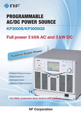
- 1. • The contents of this catalog are current as of February 10, 2012. • External view and specifications are subject to change without prior notice. • Please check the latest specifications, prices, and lead time for purchase. • The company names and product names described here are trademarks or registered trademarks of respective owners. REPRESENTATIVE Head Office 6-3-20 Tsunashima Higashi, Kohoku-ku, Yokohama 223-8508, Japan Phone: +81-45-545-8128 Fax: +81-45-545-8187 http://www.nfcorp.co.jp/english/ PU12_P-P76-1A5 Printed in Japan, Feb. 2012 Conversion of Voltage and Frequency Voltage Fluctuation Test Power Supply Simulation Stabilization of Voltage and Frequency KP3000S/KP3000GS PROGRAMMABLE AC/DC POWER SOURCE Full power 3 kVA AC and 3 kW DC Supplies Stable Power Supplies Stable Power For R&D, production lines, built-in ATE systems Model Name Description Accessories AC: 3 kVA, DC: 3 kW Connects multiple KP3000Ss by the optional system cable to configure a polyphase output system. (2 units: single-phase three-wire 6kVA; 3 units: three-phase four-wire system ) Selects the foot type or caster type on order. For KP3000S For KP3000GS The option to change foot type to caster type after purchase. KP3000S Programmable AC/DC Power Source KP3000GS Programmable AC/DC Power Source AC: 3 kVA, DC: 3 kW Equipped with sequence and simulation function, external signal input (EXT and ADD modes) and GPIB interface as standard. Not available for a polyphase system Caster type Main Unit KP3000GS KP3000S PA-001-1723 PA-001-1724 PA-001-1725 PA-001-1963 PA-001-1964 PA-001-1965 PA-001-2052 PA-001-1720 PA-001-1721 DP008 PA-001-1966 PA-001-1728 PA-001-1732 PA-001-1973 PA-001-1974 Sequence and Simulation Adds EXT and ADD modes GPIB Outlet Caster Control software for KP series Control software for KP-G series System Cable (for single-phase three-wire) System Cable (for 3-phase) Remote Controller Replacement Air Filter Rack Mount Adapter EIA (inch) Rack Mount Adapter JIS (millimeter) Additional Power Cable for 100 V input Additional Power Cable for 200 V input Adds sequence and simulation function. Adds EXT and ADD as the signal source. Adds GPIB interface Two AC outlets (NEMA 5-15: for Japan/North America) are added to the bottom of the front panel. Attaches the casters with the freely movable front-wheels and fixed rear-wheels and an an adjustable foot, instead of feet. Panel operation, editing/transferring the arbitrary waveforms, and editing/exporting/ performing sequence and simulation Single-phase three-wired 6kVA system can be configured by connecting two KP3000Ss Three-phase 9kVA system can be configured by connecting three KP3000Ss Remote controller equipped with ten key and jog dial Replacement air filters. Two types, double filters. A set of brackets to mount the product on the EIA standard compliant rack A set of brackets to mount the product on the JIS standard compliant rack When you need two or more calbles, or you change the power environment , and so on, additional purchase is possible. Ordering Information : Standard equipped : On order : On order or after purchase Notes The permission for exportation of the Japanese Administration is necessary for export outside Japan. (KP3000S corresponds to Clause 2 (8) Frequency converter, Appendix 1 of Export Trade Control Ordinance.) Option Instruction manual Power cable (Select 100 V input or 200 V input on order.) Inglish instruction manual Power cable (200 V input) Product Name Model Name Description Remarks
- 2. 1 2 PROGRAMMABLE AC POWER SOURCE KP3000S/KP3000GS For prototype evalution in the stage of development, various tests in the production and inspection lines, and the stabiliz- ation of power lines at the laboratories... Test of Power Circuits Test of DC-DC Converters Efficiency test of Airconditioners Evalution of Transformers Power Supply Voltage Test In-rush current test Voltage fulctuation test Measurement of Comsumption Power Measurement of Standby Power Stabilization Voltage and Frequency . . . . . . . Configuration of Polyphase System 3-phase 9 kVA System (A rack cabinet is sold separately.) KP3000S Multifunctional Single-phase Model KP3000GS The KP3000GS incluedes sequence and simulation function, GPIB interface, and external signal inputs (EXT and ADD) as standard. This model is suitable for Introdcution into production lines, such as household appliances KP3000GS As a Power Source for Production Lines High stability for various types of loads such as inductive and capacitive loads, low-distortion and low-noise output, and a design for ease of operability and maintainability make this power source ideal for various types of production lines. Since the 3 kVA output capacity adapts to almost all household electrical products, this single unit can flexibly support mixed production lines for various products from small to large sizes. With the addition of sequence and simulation functions tailor- ed to the line requirements, this unit powerfully supports improved production line effi- ciency and automation. For use as a built-in power source for ATE systems, this unit is equipped USB, RS-232, and GPIB* interfaces for external control input and output. External control with analog signals, contacts and status output is possible. Also external control of output range, voltage, frequency, etc. is supported. In addition, the sequence function in the main unit enables high-speed control that is not available with control software applica- tions. This power source is also equipped with a current limiter function that protects the equipment being tested in the event of emergencies to always maintain a stable supply of power. This unit is ideal for use as a built-in power source for various types of ATE systems for R&D and in production lines. As a Built-in Power Source for Automated Test Equipment By connecting multiple KP3000Ss*, a polyphase system can be configured. - Single-phase thee-wire 6 kVA (2 cabinets) - Three-phase 9 kVA (3 cabinets) * Using an optional system cable; PA-001-1720: for 1P3W PA-001-1721: for 3P4W *Option for KP3000S; Standard equipment for KP3000GS Output capacity AC : Single-phase 3 kVA, DC : 3 kW Output voltage AC : 0 to 155 V/ 310 V DC: -220 V to +220 V/ -440 V to +440 V Maximum current AC : 30 A/15 A (100 Vrms/ 200 Vrms output) DC: 30 A/ 15 A (100 Vdc /200 Vdc output) Peak current : 4 times Output Waveform : Sine, arbitrary, clipped sine AC/DC Power Source Main Specifications Measurement functions Voltage (rms value, average DC value, peak value), Current (rms value, average DC value, peak value, peak hold value), Power (active power, apparent power, reactive power), Load power factor, Crest factor, Sync frequency, Harmonic current (up to 40th order), CO2 emissions Current limiter : peak value and RMS value Remote sensing, AGC, Auto Cal Sequence function* and simulation fucntion* Functions for Various Applications A Wide Range of Interfaces to Support Automation and System Building Stable AC/DC Output for Optimal Performance. KP3000S/KP3000GS Programmable AC/DC Power Source with three output modes, AC, DC, and AC+DC for wide applications. Advanced output control ensures constant high stability for various types of loads. Various functions enable improved testing efficiency and automation as well as increased operability. For production lines manufacturing household electrical appliances in ever larger sizes, for mixed lines composed of both AC and DC equipment, and for testing of DC-DC converters, this unit provides 3 kVA/3 kW power at a reasonable price. Improved production efficiency Improved quality Reduced cost Reasonable price Reliable performance Selectable functions Rear-top side (KP3000S) RS-232, USB, GPIB*, external control I/O * Option for KP3000S; Standard equipment for KP3000GS KP3000S (Foot type, optional outlets are equipped.) Variable Current Limiter Function Stable Output Low distortion, low noise, and stable output are achieved. This power source can supply stable power to various types of loads such as inductive and capacitive loads for low power-factor loads such as equipment with large-capacity noise filters and large power output transformers. Also, with its high-quality waveform output, this unit can be used as an AC stabilized power source for precision measurements such as the power consumption and standby power of electronic equipment. Output Voltage Correction There are cases where a voltage drop occurs at the load end due to wiring. The DP Series is equipped with functions to always supply the set voltage. Remote Sensing Switches the voltage detection point used for measurement and output voltage correction to either output terminal or sensing input terminal. Output is corrected by using this together with AGC and Auto Cal. AGC This function performs continuous correction to ensure equality between the RMS values of the detection point voltage and the output voltage setting value. Even if the load fluctuates, correction is performed automatically to maintain the same value as the setting value. Auto Cal (Auto Calibration) Each time Auto Cal is turned on, this function measures the detection point voltage and performs correction to ensure that the output voltage RMS value is equal to the voltage setting value. Protection Function The KP3000S/KP3000GS has a built-in function for protecting the power source itself if a problem occurs due to issues such as output overvoltage or overcurrent, power unit trouble, internal control problems in areas such as the operation panel or communication, a rise in ambient temperature, or a drop in AC line voltage. If a problem occurs, it is displayed on the panel and output is turned off. This is used together with the current limiter function for protection against overcurrent, and it is possible to select either self-recovery after elimination of the problem, or output off after a designated time. Various Types of Output With AC 3 kVA, full-power 3kW output is also available for DC. The capacity is not reduced in DC mode. Since the AC+DC mode is also available, this power source can be used for a variety of applications. A high S/N ratio is achieved in each mode. Use of the current limiter function in DC mode enables the high performance use of the unit as a DC power source. In addition, in AC+DC mode, simulations can be performed in which the DC component is generated temporarily, such as a sudden change in voltage. AC mode DC mode AC+DC mode Low distortion Low output noise 4 times the maximum current Current RMS value Positive/negative current peak value AGC Remote Sensing Auto Cal 100 V range 0 V to155 V 30 A AC : 40 Hz to 550 Hz, AC+DC : 1 Hz to 550 Hz -220 V to +220 V 30 A 0 V to 310 V 15A -440 V to +440 V 15 A 0.1 V − 0.1 Hz 0.1 V − Output voltage Maximum current Frequency Output voltage Maximum current AC DC 200 V range Resolution Feature Output current limiting can be set with positive and negative peak values and effective value. After the activation of the limiter, the output can be automatically restored or turned off after a set time. This function is effec- tive for limiting the rush current of motors, large-capacity capac- itors, etc. and protecting against abnormal current caused when prototype operations fail. Peak value setting Example of Output Waveform <Capacitive Load 1000 µF> Current Voltage
- 3. 3 4 PROGRAMMABLE AC POWER SOURCE KP3000S/KP3000GS External Signal Input SYNC (synchronization of signal source frequency with exter- nal signals), VCA (control of output voltage with DC signals), EXT*(amplification of external signals) and ADD*(addition of external signals to internal signals) are provided. PA-001-1965 (KP3000S) Option PA-001-2052 (KP3000GS) Option for KP3000S PA-001-1723 Option for KP3000S PA-001-1964 Option for KP3000S PA-001-1723 Option DP008 Option PA-001-1963 Memory Function Store and recall settings from nonvolatile memory. USB Memory USB memory is useful for storing and making the same setting for many power sources in a production line and reading data created by the control software. Setting Range Limit Function This prevents load malfunction due to mis-operation or other problems by limiting the setting range for the output voltage upper limit and the frequency upper and lower limits. Output Relay Control A semiconductor switch can be selected for switching output on and off at high speed. Turning Output on When Powering Up This power source can be set so that the output is automatically turned on when the unit is powered up. Output On/Off Phase Setting The phase can be set from 0° to 359° at output on/off. This function is useful for the inrush current measurement. Power Unit Energization Setting The power section is modularized in 1.5 kVA units. Power units can be set on or off to suit the load capacity. This enables efficient operation while reducing power consumption. Output Waveform Monitor The waveform of the output voltage and current can be monitored (only one terminal). The current waveform can be monitored by the oscilloscope without the current clamp. Interface / External Control I/O Output Waveforms In addition to sine waves, clipped sine waves and arbitrary waves can be output. A power source test is supported that can simulate a fault in a commercial line. A clipped sine wave can be set with a crest factor or clipping ratio. An arbitrary wave can be easily created by using the optional control software and can be saved for reuse in the main unit memory through an external interface or in USB memory. Interfaces and an external control I/O provide support for system integration and automation. Interfaces RS-232, USB, GPIB*1 External control I/O Control input: Output on/off, sequence control, memory recall (basic setting memory, sequence, simulation) Status output: Power on/off, output on/off, protection operation, limiter operation, output range, step synchronization of sequence and simulation, etc. High Maintainability With its various protection functions and the current limiter function, this power source is designed to prevent damage to the load and damage to the main unit itself. If a failure occurs in one power unit, the power supply to the affected unit is interrupted and 1.5 kVA operation can be continued temporarily. With such functions to respond to operating accidents, this power source can be used with confidence for production lines. Sine wave Clipped sine wave Power Unit Modularization Arbitrary waveform Power Supply Input Flexibility Measurement Functions Abundant measurement functions comparable to those of a wattmeter are provided. Three measurement values can be selected for enlarged display to improve working efficiency in production lines. Measurement items Voltage (rms value, average DC value, peak value), Current (rms value, average DC value, peak value, peak hold value), Power (active power, apparent power, reactive power), Load power factor, Crest factor, Sync frequency, Harmonic current (up to 40th order), CO2 emissions This power source can be used regardless of the power supply environment. Top of the rear panel (KP3000S) Bottom of the rear panel Abundant useful functions tailored to the needs of power source users are provided. Setting basic parameters in multiple units Power input (AC90 V to 250 V) Output Sensing input (Using for the output voltage correction; refer to P. 2) Clipped sine wave Arbitrary waveform CONTROL I/O USB RS-232 GPIB*1 SYSTEM I/O*2 *Option for KP3000S; standard equipment for KP3000GS *1 Option for KP3000S; Standard equipment for KP3000GS *2 KP3000S only Abandant Functions for Improving the Efficiency of Power Supply Testing Programmable Sequences Voltage Fluctuation Testing Example of AC line simulation Example of output pattern Voltage drops to 70 V Voltage rises 0.02 s 0.5 s 10 s Normal voltage 100 V Step1 Step2 Step3 Step0 Step0 Sweep Keep Const Hold Time Output voltage Sweep Sequence setting Logging of measured values Programming of various test patterns such as test repetition, combinations of complex test conditions, and long- term testing enable automated test sequences. Power source tests for each destina- tion can be performed efficiently. When purchased with the optional control software, this power source can be freely programmed with very long and complex output patterns. AC line simulation Simulates a problem in the power AC line such as blackout, voltage rise, voltage drop, abrupt phase changes, or abrupt frequency change, thereby enabling all types of AC line simulation such as prototype evaluation and product inspection. When purchased with the optional control software, this power source can be easily programmed with various test conditions. Remote Controller A remote controller is provided that allows users to remotely perform operations and settings. The remote controller features a numeric keypad and jog dial that enable operations and settings similar to those on the operation panel of the main unit to be performed. Outlet Two AC outlets (NEMA 5-15: for Japan/North America) are provided at the bottom of the front panel. Control Software The optional control software enables basic parameter opera- tions, data logging, arbitrary wave editing and transmission, and editing and control of sequences and simulations on a PC. Complex programs can be easily created to automate various types of tests in production lines. AC outlet Caster The casters with the freely movable front-wheels and fixed rear- wheels are attached insted of foot type. You can select foot type or caster type on order. KP3000GS is not available for the foot type. Number of steps: Max. 255 (in 1 sequence) Setting items: Step time, output range, AC/DC mode, DC voltage, AC voltage, frequency, waveform, start phase, stop phase, phase angle, step termination, jump count, etc. Sequence control: Start, stop, hold, resume, branch 1, branch 2 Number of memories: 5 (nonvolatile) Number of steps: 6 (Initial, Normal 1, Trans 1, Abnormal, Trans 2, Normal 2) Setting items: Step time, output range, AC voltage, frequency, start phase, stop phase, trigger output, etc. Waveform: Sine wave Number of memories: 5 (nonvolatile) Editing for simulation Arbitrary waveform editing Sequence editing
- 4. 5 6 KP3000S/KP3000GS PROGRAMMABLE AC/DC POWER SOURCE Voltage Frequency, Phase Power Factor *14 Efficiency *14 Max. Power Consumption 100 V to 230 V±10% (Max. voltage 250 V) 50 Hz ±2 Hz or 6 0Hz ±2 Hz, single phase 0.95 or more (typ., at AC100 V input) , 0.90 or more (typ., at AC200 V input) 77% or more (typ., at AC200 V input) 4.5 kVA *14: In the case of AC-INT, the rated output voltage, the resistance load at the maximum current, 45 Hz to 65 Hz output. Display RMS Value DC Average (avg) (only single phase) Peak Value (pk) Max/Min Individual RMS Value DC Average (avg) (only single phase) Peak Value (pk) Max/Min Individual Display Active (W) *17 Apparent (VA) *18 Reactive (var) *18 *19 Normal Simple Load Power Factor *18 Load Crest Factor Synchronization Frequency (only sync mode) Harmonic Current *20 rms/% display CO2 Emissions Display Displays almost all measured and setting values (except harmonic current value) Displays three measurement values (except harmonic current value) enlarged. Full scale: 250.0 V/500.0 V, Resolution: 0.1 V Full scale: ±250.0 V/±500.0 V Resolution: 0.1 V Full scale: ±250.0 V/±500.0 V Resolution: 0.1 V Full scale: 40 A/20 A, Resolution: 0.01 A Full scale: ±40 A/±20 A Resolution: 0.01 A Full scale: ±160 A/±80 A, Resolution: 0.01 A Hold the maximum values of | max | and | min | with the polarity (with the clear function) Full scale: 3600 W Resolution: 0.1 W/1 W(1000 W or higher) Full scale: 4500 VA Resolution: 0.1 VA/1 VA(1000 VA or higher) Full scale: 4500 var Resolution: 0.1 var/ 1var(1000 var or higher) Measurement range: 0.00 to 1.00, Resolution: 0.01 Measurement range: 0.00 to 50.00, Resolution: 0.01 Display range: 38.0 Hz to 525.0 Hz Resolution: 0.1 Hz Measurement range: Up to 40th order. Full scale: 40 A/20 A, 100% Resolution: 0.01 A, 0.1% Instantaneous, integration value for internal loss or output power. CO2 emissions coefficient: variable Peak Current limiter *21 RMS Current limiter *21 Positive current Negative current Resolution Limiter operation Setting range (RMS) Resolution Limiter operation +15.0 Apk to +126.0 Apk/+7.5 Apk to +63.0 Apk -126.0 Apk to -15.0A pk/-63.0 Apk to -7.5 Apk 0.1 Apk Automatic recovery or output turn-off when the limited state continues over the specified time 1.5 A to 31.5 A/1.5 A to 15.8 A 0.1 A Automatic recovery or output turn-off when the limited state continues over the specified time *21: When you set the number of units by the power unit energization setting to 1, the setting range becomes half. Power Output Output Power Output Mode Rated Output Voltage Output Range Rated Output Voltage Voltage Setting Range *2 Max. Current *3 Max. Peak Current *4 Load Power Factor Frequency Setting Range Frequency Stability *5 Output Waveform Output On Phase Output Off Phase DC Offset *6 Output Power Output Mode Rated Output Voltage Voltage Setting Range Max. Current *9 Max. Instantaneous Current *10 3 kVA 1P2W Floating output, it can be used with grounding of Lo terminal. 100 V/200 V 100 V range/200 V range 0.0 V to 155.0 V/0.0 V to 310.0 V, 0.0 Vp-p to 440.0 Vp-p/0.0 Vp-p to 880.0 Vp-p (Arbitrary waveform) 0.1 V ±(0.5% of set + 0.6 V/1.2 V) 30 A/15 A 4 times value of maximum current (Apk) 0 to 1 (lead or lag, at 45 Hz to 65 Hz, external power injection and regeneration are not available.) AC mode: 40 Hz to 550 Hz, AC+DC mode: 1 Hz to 550 Hz 0.1 Hz ±0.01% of set (23˚C±5˚C) ±0.005% Sine, arbitrary (16 types), clipped sine (3 types) 0.0 deg. to 359.9 deg. variable (resolution 0.1 deg.) 0.0 deg. to 359.9 deg. variable (resolution 0.1 deg. selectable between active or inactive) Within ±20 mV (typ., fine adjustment available) 3 kW Floating output, it can be used with grounding of Lo terminal. 100 V/200 V -220 V to +220 V/-440 V to +440 V 0.1 V ± (|1% of set | +0.6 V/1.2 V) 30 A/15 A 4 times value of maximum current (Apk) Fluctuation with input voltage *11: within ±0.15% Fluctuation with output current *12: within ±0.15 V/±0.30 V (DC), within ±0.15 V/±0.30 V (45 Hz to 65 Hz), within ±0.5 V/±1.0 V (40 Hz to 550 Hz) Fluctuation with ambient temperature *13: within ±0.01%/˚C 0.5% or lower (40 Hz to 550 Hz, 50% or more of rated output voltage, maximum output current or below, AC and AC+DC modes Resolution Resolution Accuracy Resolution Accuracy *8 Output Voltage Stability Output Voltage Distortion Factor AC/DC Mode, Signal Source Power Input Measurement Function Current Limiter Sequence Function Other Functions Simulation Control Software (Option) Generals Dimension Drawings Single-phase Polyphase System (KP3000S only) AC, AC+DC, DC AC, AC+DC INT, VCA, SYNC INT, VCA, SYNC, EXT*, ADD* Specifications Configuration of Polyphase System By connecting multiple KP3000Ss, a polyphase system can be configured. (KP3000S only) 2 cabinets Single-phase thee-wire 6 kVA Using a system cable for 1P3W (PA-001-1720) Using a system cable for 3P4W (PA-001-1721) 3 cabinets Thee-phase 9 kVA * Option for KP3000S The following settings and conditions are provided unless otherwise noted. • Load: resistance load for power factor 1 • AGC/Auto Cal: OFF • Signal source: INT (internal signal source) • Current limiter: factory default setting • Output voltage waveform: sine wave • Output terminal: rear panel output terminal block [set] indicates a setting value. When two values are indicated with a slash, this means that specifications vary depending on the output range. The value before the slash is for 100 V specifications, and the value after the slash is for 200 V specifications. AC/DC Mode Signal Source AC Output * 1 DC Output * 7 Voltage Current * 15 Power * 16 *1: [V] = Vrms, [A] = Arms, and power supply input voltage is 200 V, unless otherwise specified. *2: In the case of 10 V to 150 V/20 V to 300 V, sine wave, no load, 45 Hz to 65 Hz, DC voltage setting 0 V, 23˚C ± 5˚C *3: If the output voltage is higher than the rated value, this is limited (lowered) to satisfy the power capacity. If there is the DC superimposition, the RMS current of AC+DC satisfies the maximum current. In the case of 40 Hz or lower or 400 Hz or higher, and the ambient temperature is 40˚C or higher, the maximum current may decrease. *4: For the capacitor input type rectified load (crest factor=4), the rated output voltage, and 45 Hz to 65 Hz. *5: For 45 Hz to 65 Hz, the rated output voltage, no load and the resistance load for the maximum current, and the operating temperature. *6: In the case of AC mode and 23˚C ±5˚C *7: [V]=Vdc, [A]=Adc, the power input voltage is 200 V, and the polarity is relative to Lo terminal, unless otherwise specified. *8: In the case of -212 V to -10 V, +10 V to +212 V/-424 V to -20 V, +20 V to +424 V, no load, AC setting 0 V, 23˚C ±5˚C. *9: If the output voltage is higher than the rated value, this is limited (lowered) to satisfy the power capacity. If there is the AC superimposition, the RMS current of DC+AC satisfies the maximum current. In the case that the ambient temperature is 40˚C or higher, the maximum current may decrease. *10: Instantaneous = within 2 ms, at the rated output voltage *11: For power input 90 V to 250 V, power input 200 V reference, the resistance load at maximum current, the rated output *12: In the case that the output current is changed from 0% to 100% of maximum output current. For output voltage 75 V to 150 V/150 V to 300 V, no load reference. However, if the output voltage is higher than the rated value, the maximum current is limited to satisfy the power capacity. *13: For power input 200 V, no load, the rated output voltage, DC or 45 Hz to 65 Hz. *15: In the case that output current is 5% to 100% of maximum current. *16: In the case of sine wave, 50 V or higher output voltage, and that output current is 10% or higher of maximum current. *17: For the load with power factor 1 *18: Excluding DC mode *19: For the load with power factor 0.5 or lower *20: AC-INT mode, fundamental wave 50 Hz/60 Hz only Withstanding Voltage Insulation Resistance Operating Temperature/Humidity Dimensions (W×H×D) mm Weight (approx.) Accessories AC 1500 V or DC 2130 V (inputs vs. outputs/chassis, inputs/chassis vs. outputs) 30 MΩ or higher (DC 500 V), (inputs vs. outputs/chassis, inputs/chassis vs. outputs) 0˚C to + 50˚C, 5% to 85% RH (absolute humidity 1 to 25 g/m3 , no condensation) 430×398×562 50 kg Instruction manual, power cable (KP3000S: for 100 V or 200 V AC input (Select on order); KP3000GS: for 200 V AC input) Number of Memories Number of Steps Setting Range of Step Time Operation within Step Parameters Sequence Control 5 (nonvolatile) 255 max. (for each sequence) 0.0010 s to 999.9999 s Constant, keep, linear sweep Output range , AC/DC mode, AC phase voltage, frequency, waveform, DC voltage, start phase, stop phase, phase angle, step termination, jump count (1 to 9999, or infinite), specification of the jump-to step, synchronous step output (2 bit), specification of the branch step, trigger output Start, stop, hold, resume, branch 1, branch 2 Sequence function works with AC-INT, AC+DC-INT and DC-INT. AC voltage, frequency, waveform, start phase and stop phase cannot be set with DC-INT. Number of Memories Number of Steps Step Time Setting Range Parameters Simulation Control 5 (nonvolatile). 6 (initial, normal 1, transition 1, abnormal, transition 2, normal 2). 0.0010 s to 999.9999 s (0 s can be set for transition steps only). Output range, AC voltage, frequency, waveform (sine wave only), start phase (excluding transition steps), stop phase (excluding transition steps), synchronous step (2 bit), trigger output, repeat count (1-9999 times or infinite). Start, stop. In simulation function, only AC and sine wave, fixed for AC+DC-INT. Remote Control Status Monitor Logging Arbitrary Waveform Sequence and Simulation CPU Memory Free Hard Disk Space Display OS Disk Drive Interface Parameter setting, saving, loading, and others. Monitors and displays status of connected equipment. Reads and saves measured values. Waveform creation and edit, transfer, display and file operations Sequence data creation, edit, save, transfer, preview, execution control, monitor/display during execution, and others. 300 MHz min. (1 GHz min. recommended) 256 MB min. (512 MB min. recommended) 50 MB min. Can display 1024 × 768 pixels or more, and 256 colors or more Windows 2000/XP/Vista (made by Microsoft) CD-ROM drive USB 1.1 or higher Setting range limit function Remote Sensing AGC Autocal (Automatic Calibration) Clipped Sine Wave Arbitrary Wave Memory Function Protections External Control I/O Interface USB Memory Output Waveform Monitor LCD Display Others AC mode: Voltage (RMS), AC+DC mode: Positive voltage, negative voltage (peak value) Upper limit or lower limit. Voltage detection point is output terminal or sensing input terminal. (switchable) Function for continuously performing automatic correction so that the RMS value of the detection point is equal to the voltage setting value. Response time less than 100 ms (typ.) (At DC/50 Hz/60 Hz, rated output voltage) When the Autocal is on, the detection point is always measured, and the output voltage is continuously corrected so that its RMS value is equal to the output setting value. Number of memories: 3 (nonvolatile) CF variable range: 1.10 to 1.41; setting resolution: 0.01; RMS value correction: yes Clip ratio variable range: 40.0% to 100.0%; setting resolution: 0.1%; RMS value correction: no Number of memories: 16 (nonvolatile) Waveform length: 4096 words Amplitude resolution: 16bit Sync signal source switching: external sync signal (EXT) or power input (LINE) Sync frequency range: 40Hz to 500Hz Gain setting range: 0.0 to 220.0 times/ 0.0 to 440.0 times, Resolution: 0.1, Input voltage range: ±2.2 V Gain setting range: 0.0 to 220.0 times / 0.0 to 440.0 times, Resolution: 0.1 Input voltage range: ±2.2 V Input frequency range: DC to 550 Hz (sine wave), DC to 100 Hz (other than sine wave) Store and recall settings from nonvolatile memory Number of Memories: Basic settings: 30 Protective operation for abnormal output (output overvoltage, output over current, etc.), power unit error, and internal control error (internal communication error, etc.) Enables control of the system using external signals (or no-voltage contacts) Control input, state output USB interface [USB1.1, USBTMC] RS-232 interface (not capable of binary transfer) GPIB interface (IEEE 488.1 std 1987) (not capable of binary transfer or serial polling) Usable memory: conforms to USB 1.1 or USB 2.0, Connector: USB-A (front panel) Readable/writable content: basic setting memory, sequence, AC line simulation, arbitrary wave. Monitors waveform of output voltage or output current. (switchable) 5.7 inch, contrast 0 to 99, blue or white base color. Power unit energization setting, beep, key lock, output setting at power-on, trigger output setting, time unit setting, reset function. Voltage Frequency KP3000S (Foot type) KP3000GS Option for KP3000S Option for KP3000S Option for KP3000S Option for KP3000S External Signal Input External Sync Input (Sync mode) VCA Input (VCA mode) External Signal Input (EXT/ADD mode) Functions Operating Environment Refer to the dimension of KP3000GS for the caster. KP3000S (Caster type) Rear View Rear View
- 5. • The contents of this catalog are current as of February 10, 2012. • External view and specifications are subject to change without prior notice. • Please check the latest specifications, prices, and lead time for purchase. • The company names and product names described here are trademarks or registered trademarks of respective owners. REPRESENTATIVE Head Office 6-3-20 Tsunashima Higashi, Kohoku-ku, Yokohama 223-8508, Japan Phone: +81-45-545-8128 Fax: +81-45-545-8187 http://www.nfcorp.co.jp/english/ PU12_P-P76-1A5 Printed in Japan, Feb. 2012 Conversion of Voltage and Frequency Voltage Fluctuation Test Power Supply Simulation Stabilization of Voltage and Frequency KP3000S/KP3000GS PROGRAMMABLE AC/DC POWER SOURCE Full power 3 kVA AC and 3 kW DC Supplies Stable Power Supplies Stable Power For R&D, production lines, built-in ATE systems Model Name Description Accessories AC: 3 kVA, DC: 3 kW Connects multiple KP3000Ss by the optional system cable to configure a polyphase output system. (2 units: single-phase three-wire 6kVA; 3 units: three-phase four-wire system ) Selects the foot type or caster type on order. For KP3000S For KP3000GS The option to change foot type to caster type after purchase. KP3000S Programmable AC/DC Power Source KP3000GS Programmable AC/DC Power Source AC: 3 kVA, DC: 3 kW Equipped with sequence and simulation function, external signal input (EXT and ADD modes) and GPIB interface as standard. Not available for a polyphase system Caster type Main Unit KP3000GS KP3000S PA-001-1723 PA-001-1724 PA-001-1725 PA-001-1963 PA-001-1964 PA-001-1965 PA-001-2052 PA-001-1720 PA-001-1721 DP008 PA-001-1966 PA-001-1728 PA-001-1732 PA-001-1973 PA-001-1974 Sequence and Simulation Adds EXT and ADD modes GPIB Outlet Caster Control software for KP series Control software for KP-G series System Cable (for single-phase three-wire) System Cable (for 3-phase) Remote Controller Replacement Air Filter Rack Mount Adapter EIA (inch) Rack Mount Adapter JIS (millimeter) Additional Power Cable for 100 V input Additional Power Cable for 200 V input Adds sequence and simulation function. Adds EXT and ADD as the signal source. Adds GPIB interface Two AC outlets (NEMA 5-15: for Japan/North America) are added to the bottom of the front panel. Attaches the casters with the freely movable front-wheels and fixed rear-wheels and an an adjustable foot, instead of feet. Panel operation, editing/transferring the arbitrary waveforms, and editing/exporting/ performing sequence and simulation Single-phase three-wired 6kVA system can be configured by connecting two KP3000Ss Three-phase 9kVA system can be configured by connecting three KP3000Ss Remote controller equipped with ten key and jog dial Replacement air filters. Two types, double filters. A set of brackets to mount the product on the EIA standard compliant rack A set of brackets to mount the product on the JIS standard compliant rack When you need two or more calbles, or you change the power environment , and so on, additional purchase is possible. Ordering Information : Standard equipped : On order : On order or after purchase Notes The permission for exportation of the Japanese Administration is necessary for export outside Japan. (KP3000S corresponds to Clause 2 (8) Frequency converter, Appendix 1 of Export Trade Control Ordinance.) Option Instruction manual Power cable (Select 100 V input or 200 V input on order.) Inglish instruction manual Power cable (200 V input) Product Name Model Name Description Remarks