Test High-Voltage Devices up to +250V and ±320mA
•
0 likes•47 views

This document summarizes a DC voltage current source/monitor device that is suitable for testing high-voltage semiconductors and LED luminaires. The device can output voltages up to +250V and currents up to ±320mA with high accuracy of ±0.02%. It has various measurement and sweep functions including pulse measurement with a minimum pulse width of 50μs. The device also has a suspend function to control the output status and prevent transient currents when connecting voltage sources.

Recommended
Recommended
More Related Content
What's hot
What's hot (20)
Similar to Test High-Voltage Devices up to +250V and ±320mA
Similar to Test High-Voltage Devices up to +250V and ±320mA (20)
More from NIHON DENKEI SINGAPORE
More from NIHON DENKEI SINGAPORE (20)
Recently uploaded
Recently uploaded (20)
Test High-Voltage Devices up to +250V and ±320mA
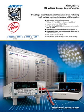
- 1. 6247C/6247G DC Voltage Current Source/Monitor DC voltage current source/monitor suitable for evaluating high-voltage semiconductors and LED luminaires http://www.adcmt-e.com RS232 6247G 6247C l Wide ranging source and measurement Voltage: -15 V to +250 V Current: 0 to ±320 mA l Source resolution of 100 μV/100 pA l 5½-digit display (±320999) with measurement resolution of 10 μV/10 pA l Basic source and measurement accuracy of ±0.02% l Pulse measurement with minimum pulse width of 50 μs and resolution of 1 μs l Sink-enabled bipolar output l GPIB (6247G), RS232 (6247C) and USB (6247G/6247C)
- 2. Source Measure Unit Capable of Testing High-Voltage Devices Output Voltage Up to +250 V and Output Current Up to ±320 mA High Voltage I-V Characteristics −Sink +Sink −Source Voltage: -15V to +250V, Current: 0 to ±320mA +Source +320mA +250V –15V –320mA VSIM、VSVM、VSRM、ISVM、ISIM、ISRM Hi-OUTPUT Hi-SENSE Lo-SENSE Lo-OUTPUT OPR/STBY Im Is Vs Vm A V 2 The 6247C/6247G is a DC voltage current source/moni- tor designed for evaluating high voltage semiconductors and LED luminaires that demand high efficiency and low power consumption, capable of outputting volt- age up to +250 V and current up to ±320 mA. It pro- vides high accuracy of ± 0.02% with 4½-digit display for source and 5½-digit display for measurement. The source resolution of 100 µV and the measurement reso- lution of 10 µV in the 5 V range enables high-precision evaluation at +3 V to +5 V necessary for LEDs or lithi- um-ion batteries. In addition, the 6247C/6247G is equipped with the various types of sweep functions such as linear, fixed, random and two slope linear sweep functions, the pulse measurement function with the minimum pulse width of 50 μs, the micro voltage and current measure- ment function with the minimum resolution of 10 μV or 10 pA, and the suspend function that controls the optimized output status. By using these functions, the 6247C/6247G can be widely used for evaluating or test- ing semiconductor and other electronic components in R&D fields and production lines. RS232 and USB are installed as standard interface for the 6247C and GPIB and USB for the 6247G, allowing easy construction of automated production lines. Source and Measurement Functions Output Range Voltage source, current source, voltage measurement, current mea- surement and resistance measurement are available by specifying the source and measurement functions. Easy setting with rotary knob Switching between voltage source (VS) and current source (IS) by one-touch operation Easy-to-read fluorescent display Parallel display of source and measurement values Output: +250V/±320mA Micro voltage/current measurement: 10µV/10pA Minimum pulse output: 50µs Source mode selectable from DC, pulse, sweep and pulse sweep Measurement function (monitor) easy selectable from voltage, current and resistance Suspend function that extends relay service life and achieves high throughput
- 3. Measurement DC Continuous stop Fixed sweep Linear sweep Random sweep Two slope linear sweep PULSE OPERATE Vsus OV LOVL (Conventional) LO VL HI VL CV CC CV CC Charge Discharge Caution! For IS, applying external voltage above the voltage limiter will set overload. Reducing transient current at output ON DUT 6247C/6247G OPR/STBY LoZ/HiZ (Semiconductor relay image) Vsus Output OFF status Output relay Output status Current limiter setting value IS: 30 digits in the setting current range (100 digits in 3μA range) HiZ ON Vsus, high resistance 100nA STBY OFF Open ー Vsus: Setting suspend voltage (default: 0V) VS: Setting current limiter (IL) LoZ ON Vsus, low resistance SUS SWEEP SUS PULSE SUS DC SUS SWEEP SUS 3 HI/LO Limiters Separate Setting Voltage and Current Source Mode Suspend Function In voltage or current source, the HI/LO limiter settings are very im- portant. For current source, the limiter voltage must be higher than the applied voltage. When voltage higher than the limiter voltage is applied from the out- side, the instrument detects overload and sets standby. When a capac- itor is discharged after being charged at a constant current with the positive and negative limiters being set to the same value, overload occurs if the limiter voltage is lowered. In addition, it is discharged down to negative voltage when applying reverse polarity current. However, the 6247C/6247G has a function that can set the HI and LO limiters individually. Furthermore, for the voltage-limiter, both HI and LO limiters can be set homo-polar. This prevents a capaci- tor or a battery from being over-discharged. Also, it is suitable for evaluating devices such as LDs that are used at a constant current and do not tolerate reverse voltage application. There are four source modes; DC, pulse, DC sweep, pulse sweep. Then, the sweep modes are classified into four sweep types: fixed sweep, linear sweep, random sweep (any type of waveform genera- tion by user's programming), two slope linear sweep (linear sweep with step value switching). The minimum pulse width is 50 μs. The minimum cycle is 2 ms, or 500 μs without measurement. The 6247C/6247G can select from three output OFF statuses; STBY (output relay OFF), HiZ (output relay ON and high resis- tance), and LoZ (output relay ON and low resistance). Using this function can omit unnecessary relay ON/OFF operations, which extends the relay lifetime and improves the system throughout. In addition, the setting of a suspend voltage (voltage in HiZ and LoZ status) can prevent transient current from being generated when connecting voltage sourcing devices such as batteries. When a conventional generator or electronic load is connected with a battery, the output voltage is 0V, and then the setting cur- rent starts flowing. In this case, the moment that it is connected, transient current sink occurs, causing unnecessary battery dis- charge. On the other hand, by setting the suspend voltage, the 6247C/6247G is connected in high-impedance state at the speci- fied voltage and then the setting current flows. This prevents un- necessary discharge at the connection to the battery. For the 6247C/6247G, the source modes can be switched in such suspend status, which improves the throughput. (Continuous testing is possible without disconnecting DUTs.)
- 4. Wide ranging applications for high-voltage semiconductors and LEDs by pulse application test with low power consumption Wide Use of DC Voltage Current A/D conversion (100µs) Sampling Sampling Hold T d s Voltage Time Tw Rising edge 175V/250μs Falling edge 175V/250μs Connection Diagram Connection Diagram Measurement Waveform HI LO LO HI 6247C/6247G 2W/4W 2W/4W V I IF V IF TW TP VF Current (IF) Volteage (VF) VF temperature dependence by pulse(Tw) variation 6247C/6247G I V IR I V −100μA 4 Diode Temperature Dependence Evaluation Diode Leak Current Measurement Current Application Response Sample Hold Measurement In I-V characteristic test on devices that generate heat when current flows, applying pulse current is effective for avoiding the influence of the self-heating. By using the current pulse sweep function and voltage measurement in synchronous with pulses, precise VF characteristic test with large current is available. ● Pulse sweep function ● Current setting range: 0 mA to ±320 mA ● Voltage measurement resolution: 10 µA ● Pulse measurement with minimum pulse width of 50 µs and minimum cycle of 2 ms The 6247C/6247G is capable of ISVM (current source voltage mea- surement) and VSIM (voltage source current measurement). Diode I-V characteristics are measured by ISVM. In addition, micro leak current up to 10 pA can be measured by applying reverse volt- age to diodes by VSIM. Also, automatic PASS/FAIL judgment is available by using com- parison operation of the measurement calculating function. ● Sweep function ● Maximum setting range: -15 V to +250 V/±320 mA ● Current measurement resolution: 10 pA ● Measurement calculating function LED evaluation is done by ISVM (current source voltage measure- ment). When constant current is applied to a LED between 0 A and +IS, the output current becomes the setting current at the rising edge, but 0 A at the falling edge and the response time is very slow to dis- charge the device. To avoid this problem, current is applied between -IS and +IS. At this time, +VL is set to the forward voltage or higher and -VL to 0 V or minus several V to prevent reverse voltage application. The response when fifty white LEDs are connected in series is as follows: +IS = +30 mA, -IS = -30 mA, +VL = +200 V, -VL = -5 V Sample hold measurement is available in the pulse mode and the pulse sweep mode. Measurement holds an input signal immediately before pulse falling edge, and A/D conversion is implemented for integration time of 100 μs. This function enables precise values to be measured without setting the measurement delay time.
- 5. Source/Monitor 6247C rear panel 6247G rear panel PWM Series connection example (2 units) Equivalent circuit (Total voltage of 2 units) VSIM ISVM Equivalent circuit (Total current of 2 units) Pulse source mode DUT Parallel connection example (2 units) Hi Lo Hi Lo DUT 5 LED Pulse Width Modulation Brightness Evaluation To control the LED brightness, generally the pulse width modula- tion (PWM) method is used. PWM requires the constant pulse current, the pulse width and the pulse period need to be varied. This can be easily done by using the pulse source mode of the 6247C/6247G. ● Pulse source mode ● Maximum setting range: -15 V to +250 V/±320 mA ● Pulse width: 50 µs to 59998 ms ● Pulse period: 500 µs to 60000 ms Pulse value Base value Pulse width [Tw] Pulse period [Tp] High Middle Low Tp Tw3 Tw3 Tw2 Tw2 Tw1 Tw1 Tp Higher Voltage and Larger Current Device Testing USB Interface As the 6247C/6247G adopts floating bipolar output, the voltage ca- pacity or current capacity can be increased by connecting more than two units in series or in parallel. Accordingly, it is capable of testing devices such as semiconductors that need higher voltage or larger capacity. For example, connecting two units in series outputs up to +500 V/±320 mA, or two units in parallel up to ±640 mA/+250 V. Similarly, the output level that you wish is available by connecting two units in series or more than two units in parallel as shown be- low: The 6247C/6247G is equipped with a USB interface as standard, al- lowing easy data transmission from a PC. In addition to the software to capture measurement data onto Excel sheets, the USB driver and the sample software are available from our website. Number of units connected in series 1 2 Number of units con- nected in parallel 1 +250V/ 320mA +500V/ 320mA 2 +250V/ 640mA +500V/ 640mA 3 +250V/ 960mA +500V/ 960mA … … … TRIGGER IN/SYNC OUT signal to perform synchronous operation of multi-units or synchronous control on external measuring instruments and to output comparison operation results, and INTERLOCK signal to prevent malfunction RS232 interface USB interface GPIB interface
- 6. 6 Specifications All accuracy specifications are guaranteed for one year at a temperature of 23 ±5° C and a relative humidity of 85% or less. Voltage source/measurement range: Range Source range Setting resolution Measurement range Measurement resolution 5V -1.0000 to +5.0000V 100μV -1.00999 to +5.00999V 10μV 50V -10.000 to +50.000V 1mV -10.0999 to +50.0999V 100μV 250V -15.00 to +250.00V 10mV -15.099 to +250.999V 1mV Current source/measurement range: Range Source range Setting resolution Measurement range Measurement resolution 3μA 0 to 3.2000μA 100pA 0 to 3.20999μA 10pA 30μA 0 to 32.000μA 1nA 0 to 32.0999μA 100pA 300μA 0 to 320.00μA 10nA 0 to 320.999μA 1nA 3mA 0 to 3.2000mA 100nA 0 to 3.20999mA 10nA 30mA 0 to 32.000mA 1μA 0 to 32.0999mA 100nA 300mA 0 to 320.00mA 10μA 0 to 320.999mA 1μA However, the measurement resolution with integration time of 100μs, 500μs and S/H (Sample Hold) will be as follows: Integration time 100μs 500μs S/H (100μs) Measurement resolution (digits) 10 2 10 Resistance measurement range: Range Measurement range Measurement resolution Determined by voltage range/current range calculations 0Ω to 125GΩ Minimum 30μΩ Voltage limiter (compliance) range: Setting range Setting resolution*1 -1.000V to +5.000V 1mV -10.00V to +50.00V 10mV -15.0V to +250.0V 100mV Current limiter (compliance) range: Setting range Setting resolution*1 10nA to 3.2μA 1nA 3.201μA to 32μA 10nA 32.01μA to 320μA 100nA 320.1μA to 3.2mA 1μA 3.201mA to 32mA 10μA 32.01mA to 320mA 100μA *1: Where, (Hi limiter value - Lo limiter value) ≥ 60 digits (200 digits in the 3μA range) Accuracy: Includes calibration accuracy, 1-day stability, temperature coefficient and linearity Voltage source: Range Accuracy 1-day stability Temperature coefficient (% of setting+V) (ppm of setting+V)/ºC 5V 0.02 +500μV 0.01+200μV 20 +40μV 50V 0.02 +5mV 0.01+2mV 20 +400μV 250V 0.025 +50mV 0.01+20mV 20 +4mV Voltage limiter: Range Accuracy 1-day stability Temperature coefficient (% of setting+V) (ppm of setting+V)/ºC 5V 0.05+3mV 0.01+1mV 50 +300μV 50V 0.05+30mV 0.01+10mV 50 +3mV 250V 0.05+300mV 0.01+100mV 50 +30mV Voltage limiter additional error: When Hi limiter is set to a negative value and Lo limiter is set to a positive value, an error of ±0.1% of setting is added. Current source: Range Accuracy 1-day stability Temperature coefficient (% of setting+A+A Vo/1V) (ppm of setting+A+A×Vo/1V )/ºC 3μA 0.03+5nA+30pA 0.01+3nA+10pA 30+500pA+1pA 30μA 0.03+15nA+300pA 0.01+8nA+100pA 30+1.5nA+10pA 300μA 0.03+150nA+3nA 0.01+80nA+1nA 30+15nA+100pA 3mA 0.03+1.5μA+30nA 0.01+800nA+10nA 30+150nA+1nA 30mA 0.03+15μA+300nA 0.01+8μA+100nA 30+1.5μA+10nA 300mA 0.045+150μA+3μA 0.015+80μA+1μA 45+15μA+100nA Current limiter: Range Accuracy 1-day stability Temperature coefficient (% of setting+A+A×Vo/1V) (ppm of setting+A+A Vo/1V)/ºC 3μA 0.045+8nA+30pA 0.01+5nA+10pA 40+1nA+1pA 30μA 0.045+35nA+300pA 0.01+20nA+100pA 40+3.5nA+10pA 300μA 0.045+350nA+3nA 0.01+100nA+1nA 40+35nA+100pA 3mA 0.045+3.5μA+30nA 0.01+1μA+10nA 40+350nA+1nA 30mA 0.045+35μA+300nA 0.01+10μA+100nA 40+3.5μA+10nA 300mA 0.055+350μA+3μA 0.015+100μA+1μA 45+35μA+100nA Vo: Compliance voltage (-15V to +250V) Voltage measurement: (Auto zero: ON, integration time: 1PLC to 200ms) Range Accuracy 1-day stability Temperature coefficient (% of reading+V) (ppm of reading+V )/ºC 5V 0.02 +120μV 0.008 +50μV 20 +15μV 50V 0.02 +1.2mV 0.008 +500μV 20 +150μV 250V 0.02 +10mV 0.008 + 8mV 20 + 1mV Current measurement: (Auto zero: ON, integration time: 1PLC to 200ms) Range Accuracy 1-day stability Temperature coefficient (% of reading+A+A Vo/1V) (ppm of reading+A+A Vo/1V )/ºC 3μA 0.03+4nA+30pA 0.01+2.5nA+10pA 30+450pA+1pA 30μA 0.03+12nA+300pA 0.01+7nA+100pA 30+1.5nA+10pA 300μA 0.03+120nA+3nA 0.01+70nA+1nA 30+15nA+100pA 3mA 0.03+1.2μA+30nA 0.01+700nA+10nA 30+150nA+1nA 30mA 0.03+12μA+300nA 0.01+7μA+100nA 30+1.5μA+10nA 300mA 0.045+120μA+3μA 0.015+70μA+1μA 30+15μA+100nA Resistance measurement:(Auto zero: ON, integration time: 1PLC to 200ms) Condition Accuracy ±(%of reading) ±(digits+digits+digits) Voltage source Reading item: (Voltage source setting item + Current measurement reading item) Full-scale item:(Voltage source full-scale item digit value + current measurement full-scale item digit value + CMV item digit value)*2 Current source Reading item: (Current source setting item + Voltage measurement reading item) Full-scale item:(Current source full-scale item digit value + Voltage measurement full-scale item digit value + CMV item digit value)*2 Vo: Compliance voltage (-15V to +250V) *2: CMV item = (A × Vo/1V); source or measurement current × source or measurement voltage/1V digit value The full-scale item tolerances listed below are added to the integration time 100µs to 10ms, S/H measurement accuracy and 1-day stability Measurement range Integration time Unit: digits (at 5½ digit display) 10ms 5ms 1ms 500μs 100μs S/H Voltage measurement 5V 5 15 20 30 100 120 50V 5 15 20 30 100 120 250V 5 15 20 30 100 120 Current measurement 3μA 600 1000 1500 2000 2000 3000 30μA 200 300 300 300 500 2000 300μA 40 50 60 80 200 1500 3mA 40 50 60 80 200 500 30mA 40 50 60 80 200 300 300mA 40 50 60 60 200 300 S/H: Measurement in the sample hold mode (integration time: 100µs) Source linearity: 3 digits or less Maximum output current: -15V to +250V; 320mA Maximum compliance voltage: Up to 320mA; -15V to +250V Output noise: For voltage source, within the range from no load to the maximum load [Vp-p] For current source, at the following load [Ap-p] Voltage source: Range Load resistance Low frequency noise High frequency noise DC to 100Hz DC to 10kHz DC to 20MHz 5V ─ 200μV 400μV 10mV 50V ─ 300μV 1mV 10mV 250V ─ 500μV 5mV 10mV
- 7. 7 Current source: Range Load resistance Low frequency noise High frequency noise DC to 100Hz DC to 10kHz DC to 20MHz 3μA 10kΩ 10nA 60nA 800nA 30μA 10kΩ 10nA 60nA 800nA 300μA 10kΩ 50nA 150nA 800nA 3mA 1kΩ 500nA 2μA 10μA 30mA 1kΩ 4μA 10μA 20μA 300mA 1kΩ 40μA 60μA 100μA Switching noise: Typical value [p-p] Load resistance Output ON/OFF noise Voltage source 1V At 100kΩ Current source 1V At 100kΩ Range switching noise Voltage source 100mV − Voltage limiter 100mV*3 − Voltage measurement 100mV*3 − Current source 100digits+100mV*4 − Current measurement Current limiter Power OFF noise 1V At 100kΩ *3: The Limiter is inactive. While the limiter is active, it is the same as the current source range switching noise. *4: "digits" indicates current source 4½ digit values. Settling time: Time to reach the final value ±0.1% at pure resistance load and load capacity of 2.5pF and with compliance set to full scale Voltage source: at load where the output current is 20% or less of the setting limiter in the 250V range (FAST: 600 µs, SLOW: 2.5ms at full load) (Typical value) Source range Limiter range Output response FAST SLOW Voltage source 5V 3mA to 300mA 300μs 2.2ms 50V 250V Current source Output voltage: 5V 3mA 250V 120μs 30mA 300mA Current Source Output voltage: 250V 3mA 250V 800μs 4.5ms 30mA 300mA Over shoot: ±5% or less under pure resistance load and at the standard cable end(3µA, 30µA and 300µA ranges excluded) Line regulation: ±0.003% of range or less Load regulation: Voltage source: ±0.003% of range or less (at 4-wire connection under the maximum load) Current source: Depending on the accuracy CMV (A Vo/1V) Output resistance: At 4-wire connection (Output cable not included) Maximum load capacitance: Maximum load capacitance that does not generate oscillation in voltage source or voltage limiter status Output resistance (Ω) Maximum load capacitance Current range Voltage source Current source 3μA 3Ω or less 10GΩ or higher 1μF 30μA 500mΩ or less 1000MΩ or higher 1μF 300μA 100mΩ or less 1000MΩ or higher 1μF 3mA 10mΩ or less 100MΩ or higher 100μF 30mA 10mΩ or less 10MΩ or higher 100μF 300mA 10mΩ or less 1MΩ or higher 2000μF Supplied cable resistance: 100mΩ or less Maximum inductive load: Maximum inductive load that does not generate oscillation in current source or voltage limiter status Current source range/ 3µA, 30µA 300µA 3mA to 300mA current limiter range Response Maximum inductive load FAST 100µH 200μH 1mH SLOW 500µH 1mH Effective CMRR: At unbalanced impedance 1kΩ In DC and AC 50/60 Hz ± 0.08% Integration time 100µs to 10ms 1PLC to 200ms Voltage source/current measurement 35dB 95dB Current source/voltage measurement 35dB 95dB NMRR: At AC 50/60 Hz ± 0.08% Integration time 100µs to 10ms 1PLC to 200ms Voltage source/current measurement 0dB 60dB Source and measurement function DC source and measurement: Source and measurement of DC voltage and current Pulse source and measurement: Source and measurement of pulse voltage and current (However, measurement auto range in pulse source is impossible) DC sweep source and measurement: Source and measurement by Linear, Two slope linear, Random and Fixed levels Pulse sweep source and measurement: Source and measurement by Linear, Two slope linear, Random and Fixed levels(However, measurement auto range in pulse source is impossible) Integration time: 9 types available: 100µs, 500µs, 1ms, 5ms, 10ms, 1PLC, 100ms, 200ms and S/H S/H: Sample hold (integration time: 100µs) measurement (Enabled only in the pulse source and pulse sweep source modes.) (PLC: Power Line Cycle 50Hz: 20ms, 60Hz: 16.66ms) Sweep mode: Reverse ON (round) / OFF (one way) Sweep repeat count: 1 to 1000 times or infinite Maximum number of sweep steps: 8000 steps Maximum random sweep memory: 8000 data Measurement data memory: 8000 data Measurement auto range: Available only in VSIM or ISVM Measurement function link mode: Links the source function to the measurement function. (VSIM or ISVM) ON/OFF available Limiter: The HI and LO limiters can be set individually. (However, current limiters of the same polarity are not allowed.) Calculation function: NULL calculation Comparator calculation (HI, GO, or LO) Scaling calculation MAX, MIN, AVE, TOTAL calculation Trigger style: Auto trigger, External trigger Output terminal: Front; Safety socket HI OUTPUT, HI SENSE, LO OUTPUT, and LO SENSE Maximum input: +250V/-15V peak Max (between HI-LO) 2V peak Max (between OUTPUT and SENSE) 250V Max (between LO and chassis) Maximum remote sensing voltage: ±1V Max; HI OUTPUT - HI SENSE, LO OUTPUT - LO SENSE (The voltage between HI SENSE and LO SENSE must be within the maximum output voltage range.) Voltage measurement input resistance: 10GΩ or higher Voltage measurement input leak current: ±100pA or lower Interface Function GPIB: (6247G only) Compliant with IEEE-488.2-1987 Interface function; SH1, AH1, T5, L4, SR1, RL1, PP0, DC1, DT1, C0, E2 Connector; Amphenol 24 pin RS-232: (6247C only) Compliant with EIA232C (RS-232) Baud rate; 19200, 9600, 4800, 2400, 1200, 600, 300 Parity; even, odd and none Number of data bits; 7 bits, 8 bits Number of stop bits; 1 bit, 2 bits Connector; Dsub 9 pin USB interface: USB 2.0 Full-speed Connector; Type B External control signal: TRIGGER IN, INTERLOCK, OPERATE IN, OPERATE OUT,SYNC OUT Connector; BNC
- 8. © 2013 ADC CORPORATION Printed in Japan 6247C/G-NP1E Oct. '13 A Setting Time Minimum pulse width: 50µs Minimum step (repeat) time: Under fixed source/measurement range, integration time of 100µs, the minimum measurement or source delay time, calculation function OFF, and voltage/ current measurement Measurement Memory mode Minimum step time OFF − 0.5ms ON BURST 2ms NORMAL 10ms OFF Source delay time: Setting range Resolution*5 Setting accuracy 0.030ms to 60.000ms 1μs (0.1%+10μs) 60.01ms to 600.00ms 10μs 600.1ms to 6000.0ms 100μs 6001ms to 59998 ms 1ms Period (pulse cycle): Setting range Resolution*5 Setting accuracy 0.500ms to 60.000ms 1μs (0.1%+10μs) 60.01ms to 600.00ms 10μs 600.1ms to 6000.0ms 100μs 6001ms to 60000 ms 1ms Pulse width: Setting range Resolution*5 Setting accuracy 0.050ms to 60.000ms 1μs (0.1%+10μs) 60.01ms to 600.00ms 10μs 600.1ms to 6000.0ms 100μs 6001ms to 59998 ms 1ms Measurement delay time: Setting range Resolution*5 Setting accuracy 0.050ms to 60.000ms 1μs (0.1%+10μs) 60.01ms to 600.00ms 10μs 600.1ms to 6000.0ms 100μs 6001 ms to 59998 ms 1ms *5: The setting resolution is determined by the period time resolution. Hold time: Setting range Resolution Setting accuracy 1ms to 60000 ms 1ms (2% + 3ms) Auto range delay time: Setting range Resolution Setting accuracy 0ms to 5000 ms 1ms (2% + 3ms) General Specifications Operating environment: Ambient temperature: 0ºCto +50ºC Relative humidity: 85% or less, no condensation Storage environment: Ambient temperature: -25ºC to +70ºC Relative humidity: 85% or less, no condensation Warm-up time: 60 minutes or more Display: 16 segments x 12 digits vacuum fluorescent display Power supply: AC power supply 100V/120V/220V/240V (User selectable) Option number Standard OPT. 32 OPT. 42 OPT. 44 Power voltage 100V 120V 220V 240V Specify the option when ordering. Use a power cable and a fuse that are compliant with the safety standard when changing the power supply voltage. Line frequency: 50Hz/60Hz Power consumption: 160VA or less Dimensions: Approx. 212 (W) x 88 (H) x 450 (D) mm Mass: 7.3kg or less Safety: Compliant with IEC61010-1 Ed.3 EMI: EN61326-1 class A Supplied accessories: Model Name Quantity A01402 Power cable 1 A01044 Input/output cable (red and black safety cable 1m) 1 A08532 Alligator clip adapter (red and black) 1 A08531 Banana adapter (red and black) 1 Optional accessories: Model Name 12701A Test fixture A01041 Input cable (1m) A01044 Input/output cable (red and black safety cable 1m) A08532 Alligator clip adapter (red and black) A08531 Banana adapter (red and black) A01047-01 Input/output cable (banana-banana 4-wire shielding 0.5m) A01047-02 Input/output cable (banana-banana 4-wire shielding 1m) A01047-03 Input/output cable (banana-banana 4-wire shielding 1.5m) A01047-04 Input/output cable (banana-banana 4-wire shielding 2m) A01036-1500 BNC-BNC cable (1.5m) A02263 Rack mount set (JIS 2U half) A02264 Rack mount set (JIS 2U half twin) A02463 Rack mount set (EIA 2U half) A02464 Rack mount set (EIA 2U half twin) A02039 Panel mount set (2U half) A02040 Panel mount set (2U half twin) Note: When mounting the instrument on a rack, install a shelf plate or support bar as necessary. • Please read through the operation manual carefully before using the products. • All specifications are subject to change without notice. Head Office Shoei Bldg, 3-6-12, Kyobashi, Chuo-ku, Tokyo 104-0031, Japan Phone: +81-3-6272-4433 Fax: +81-3-6272-4437 Higashimatsuyama Office (R&D Center) 77-1, Miyako Namegawa-machi, Hiki-gun, Saitama 355-0812, Japan Phone: +81-493-56-4433 Fax: +81-493-57-1092 E-mail : kcc@adcmt.com URL : http://www.adcmt-e.com