Download to read offline
![3
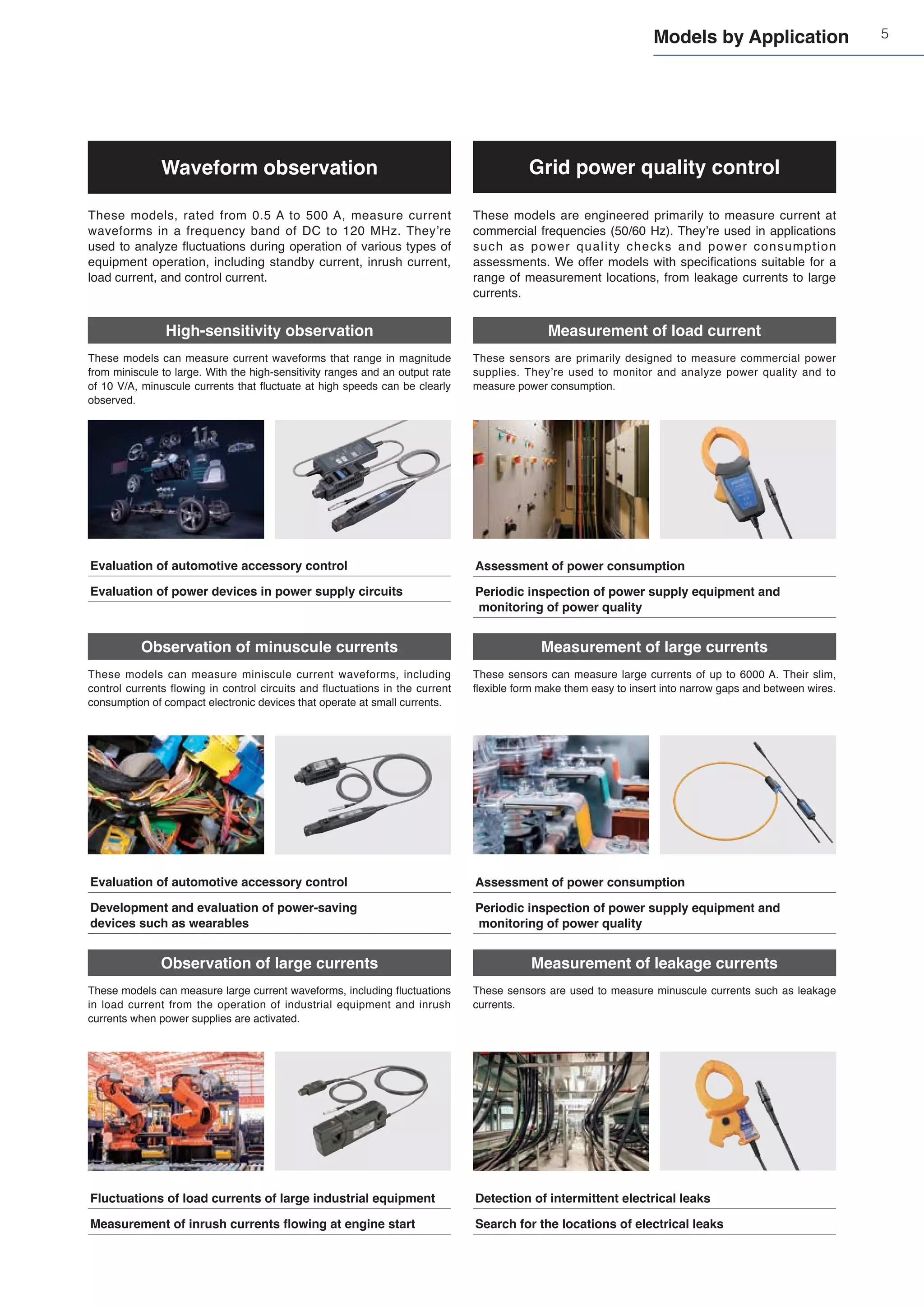
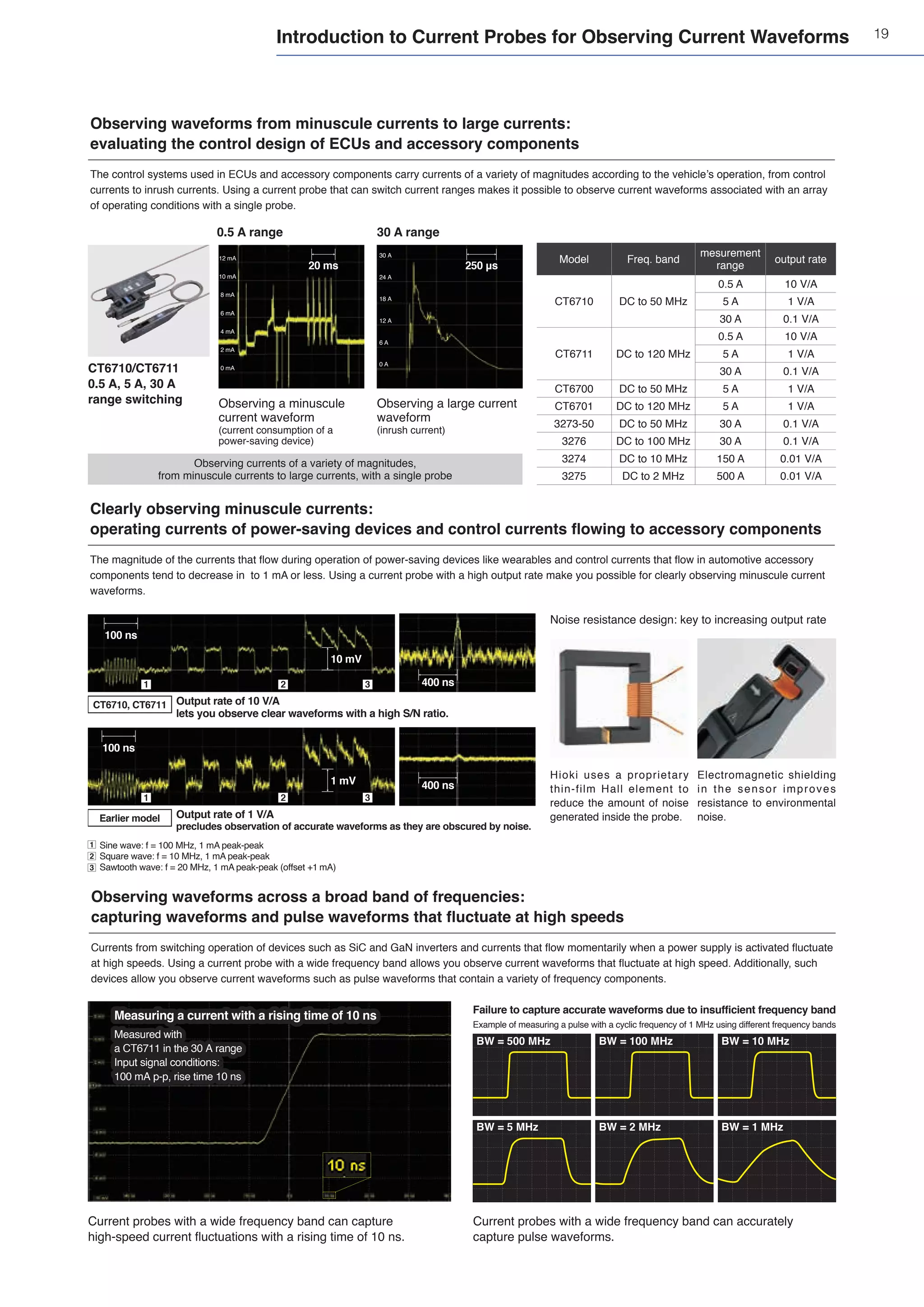
Applications by operating current and operating frequency
Use Cases
Operation
current
[A]
Operation frequency [Hz]
10 k
DC 10 k 100 k 1 M 10 M 100 M 1 G
1 k
100
100 m
10 m
1 m
100 μ
1
10
SiC
High Power
Si
Medium
Power & Speed
GaN
High Speed
Power transmission, energy storage
Bullet train
Airplane
EV, PHEV, FCV
Home appliances, PC
Server, base station
Smartphone
Production robot
Solar power, wind power generation
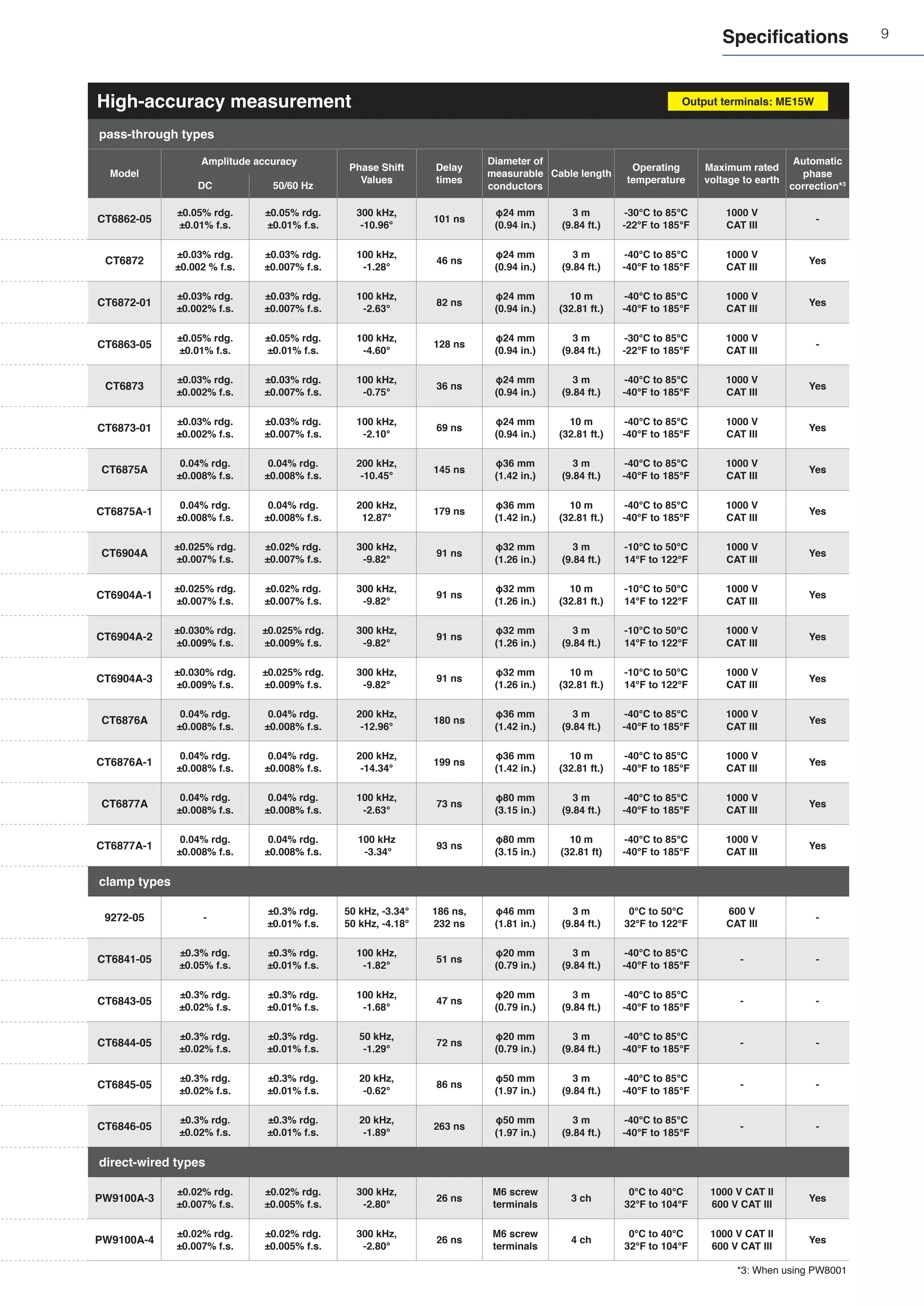
High-accuracy
measurement
pass-through types
- EV inverter systems R&D
- Assessment of reactor and transformer losses
clamp types - WLTP-compliant fuel economy (electricity cost) performance testing
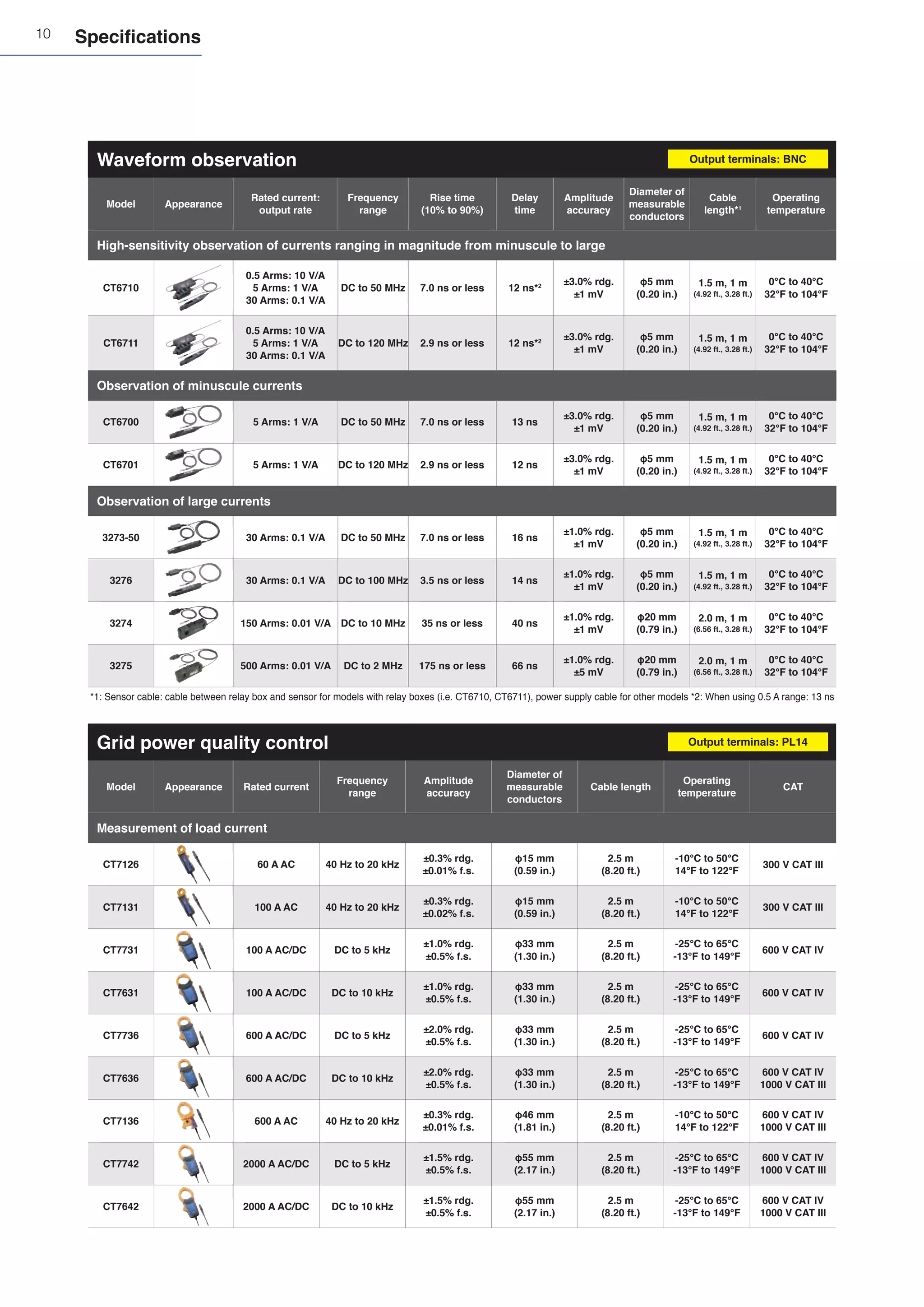
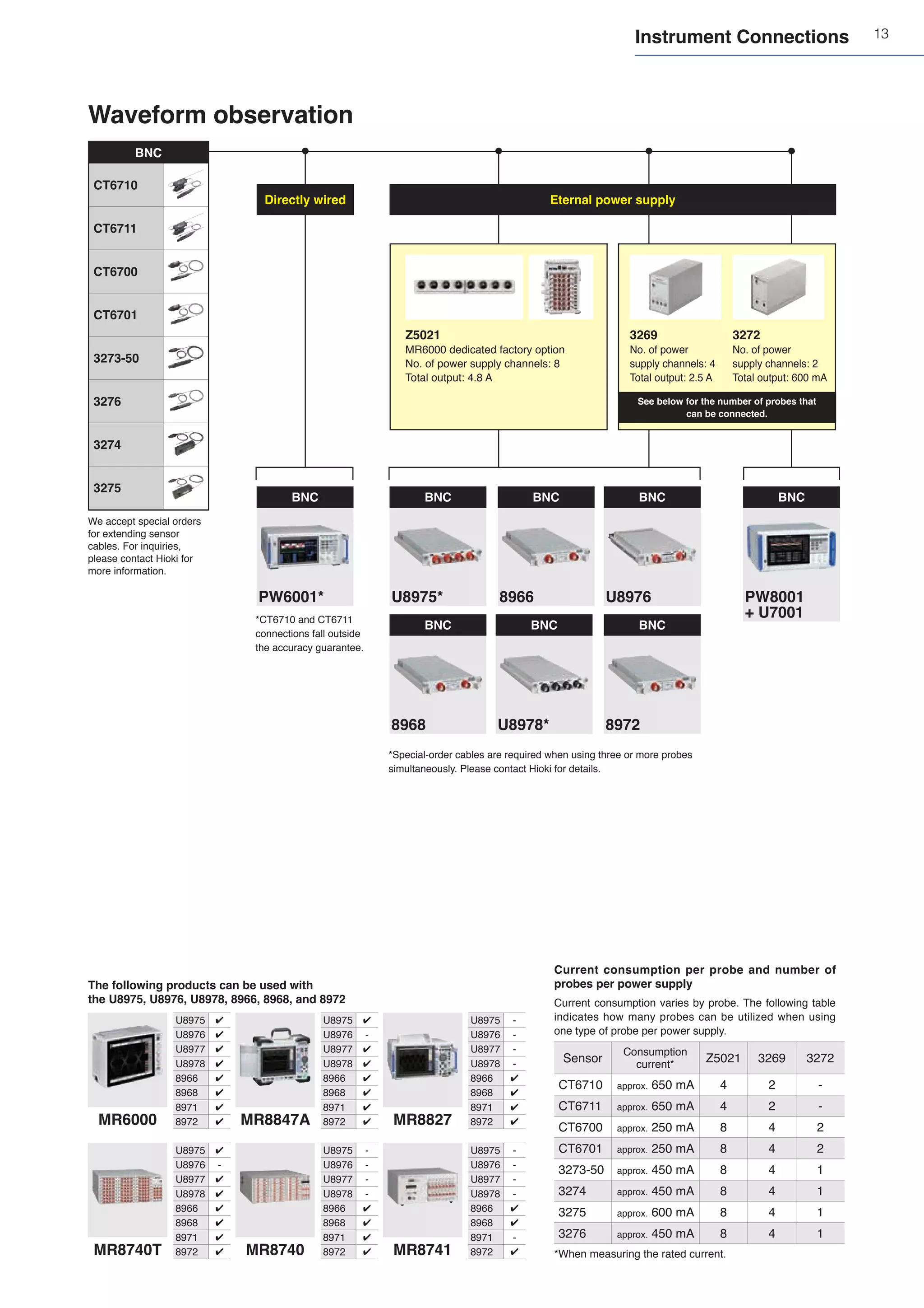
Waveform
observation
High-sensitivity
observation
- Evaluation of automotive accessory control
- Evaluation of power components in power supply circuits
Observation of
minuscule currents
- Evaluation of automotive accessory control
- Development and evaluation of power-saving devices such as wearables
Observation of
large currents
- Fluctuations in fluctuation of load currents of large industrial equipment
- Measurement of inrush currents flowing when starting an engine
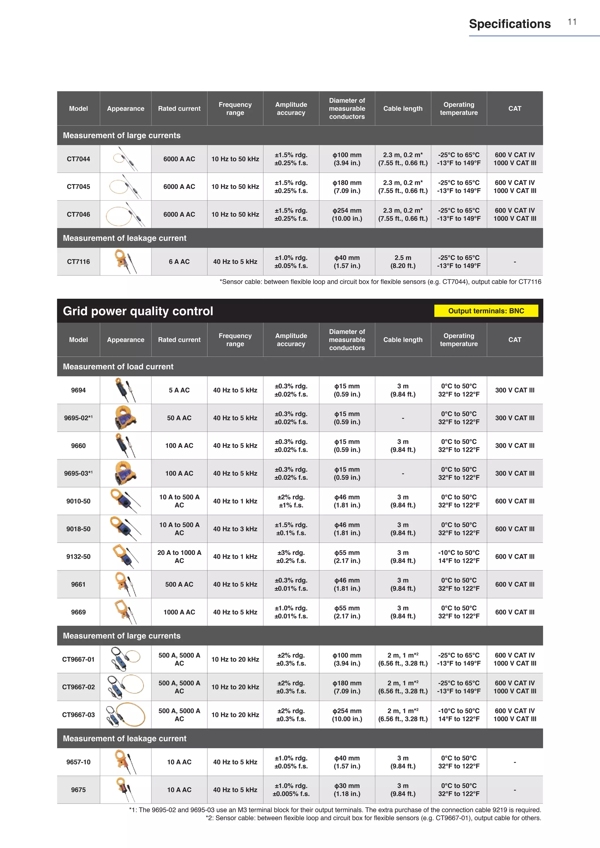
Grid power
quality control
Measurement of
load currents - Assessment of power consumption
- Periodic inspection of power supply equipment and
monitoring of power quality
Measurement of
large currents
Measurement of
leakage currents
- Detection of intermittent electrical leaks
- Search for the locations of electrical leaks](https://image.slidesharecdn.com/seriessensorsprobese1-1zb-211217051801/75/HIOKI-Current-Series-sensors-probes_e1-1_zb-3-2048.jpg)
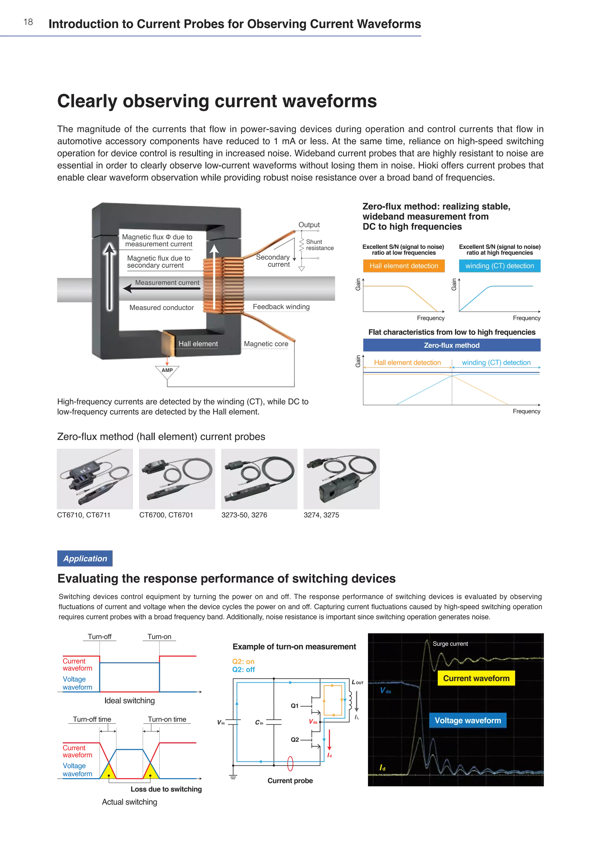
![16
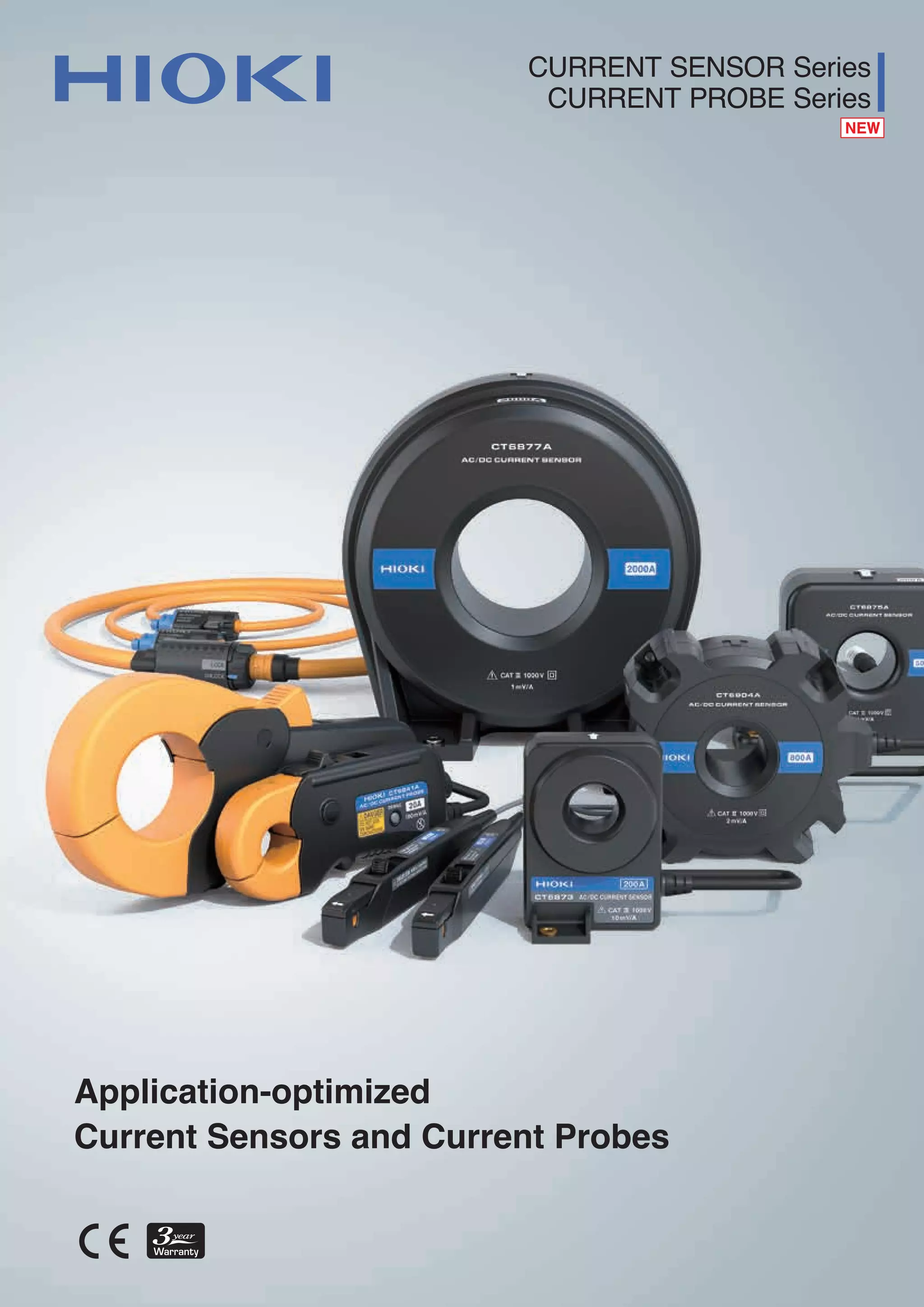
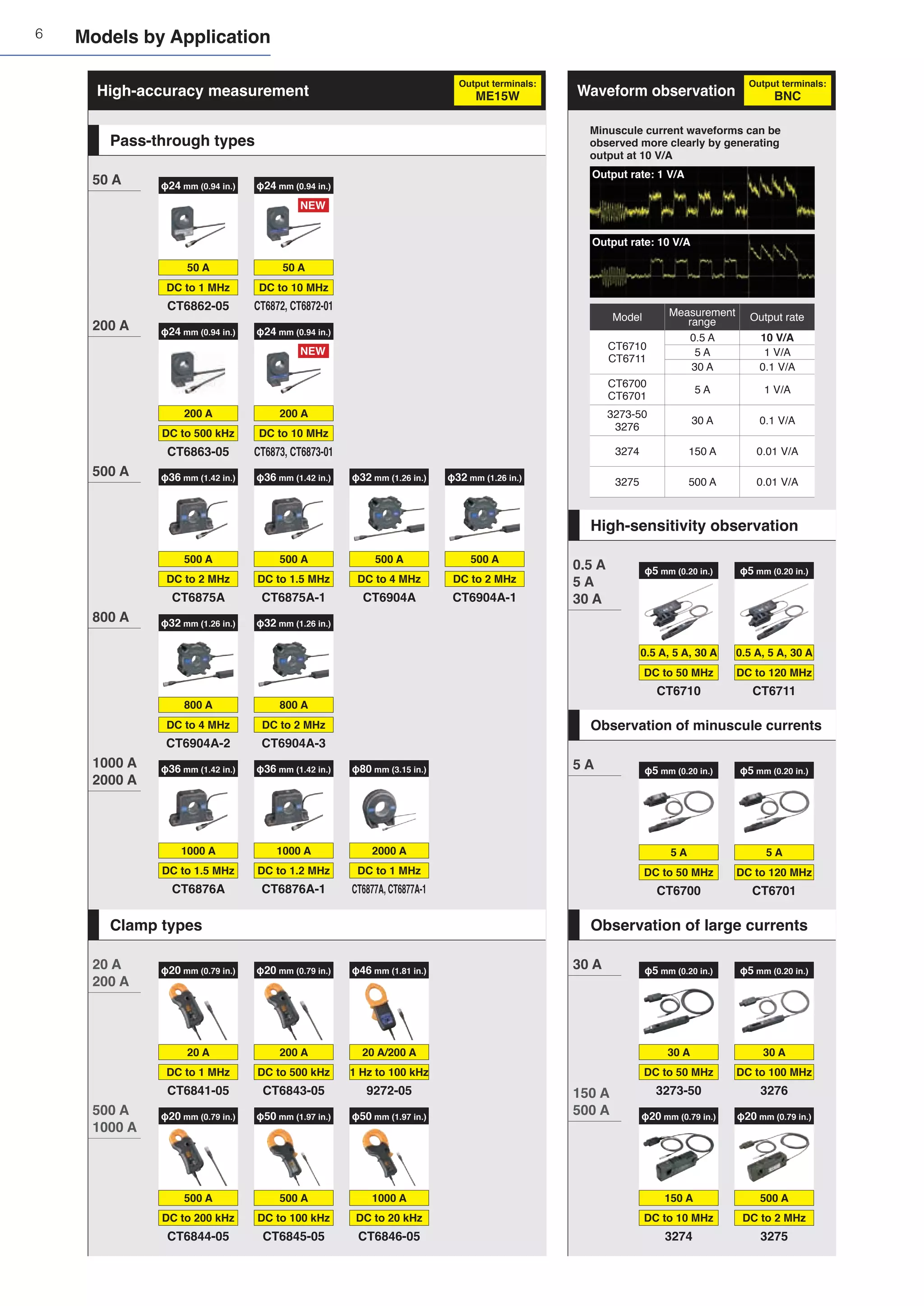
Zero-flux method: achieving stable,
wideband measurement from
DC to high frequencies
Zero-flux method (flux gate) current sensors
Application
Evaluating the power conversion efficiency of an inverter
When evaluating the power conversion efficiency of an inverter, the inverter’s input and output power are measured and its efficiency is checked. PWM (pulse
width modulated) inverter output, which has been widely used in recently years, contains a modulated wave (fundamental wave) and a switching frequency along
with their respective harmonic components. Since switching frequencies tend to be high, the process requires wide frequency band current sensors.
High-frequency currents are detected by a winding (CT),
while DC to low-frequency currents are detected by a flux gate.
Since the power factor decreases with harmonics, current sensors’
phase measurement accuracy becomes key (see right).
CT6875A, CT6876A CT6877A CT6904A
CT6862-05, CT6863-05,
CT6872, CT6873
CT6841-05, CT6843-05,
CT6844-05
CT6845-05, CT6846-05
Introduction to Current Sensors Designed for High-accuracy Measurement
Improving power conversion efficiency is a key part of the effort to facilitate the effective use of energy. Devices that
operate at high frequencies are increasingly being used to improve efficiency, and evaluation processes undertaken
during the development of such devices requires accurate measurement of power at the low frequencies used by in
previous devices as well as at high frequencies. Additionally, sensors that can resist noise are necessary since noise
becomes stronger as the frequency increases. Hioki offers current sensors that can measure power accurately while
providing robust noise resistance over a broad band of frequencies.
Accurately evaluating power conversion efficiency
Measurement current
Measured conductor
Magnetic core
2f
f
Magnetic flux Φ due to
measurement current Secondary
current
Output
Shunt
resistance
Feedback
winding
Magnetic flux due to
secondary current
Flux gate
AMP
Excitation
Detection
Flux gate detection
Flux gate detection
Excellent accuracy at
low frequencies
Excellent accuracy at
high frequencies
Flat characteristics from low to high frequencies
Gain
Frequency
Gain
Frequency
Zero-flux method
winding (CT) detection
winding (CT) detection
Gain
Frequency
Input power (DC)
Output power
(up to high frequencies)
Output power
· Modulated wave (fundamental wave) + harmonics
· Switching frequency + harmonics
Evaluation of power
conversion efficiency
Inverter Motor
Battery
Inverter output: principal active power components
Modulated wave
(fundamental wave) +
harmonics
Switching frequency +
harmonics
High power factor Low power factor
Active power [W]
Frequency [Hz]
1 kHz 10 kHz 100 kHz 1 MHz](https://image.slidesharecdn.com/seriessensorsprobese1-1zb-211217051801/75/HIOKI-Current-Series-sensors-probes_e1-1_zb-16-2048.jpg)
![17
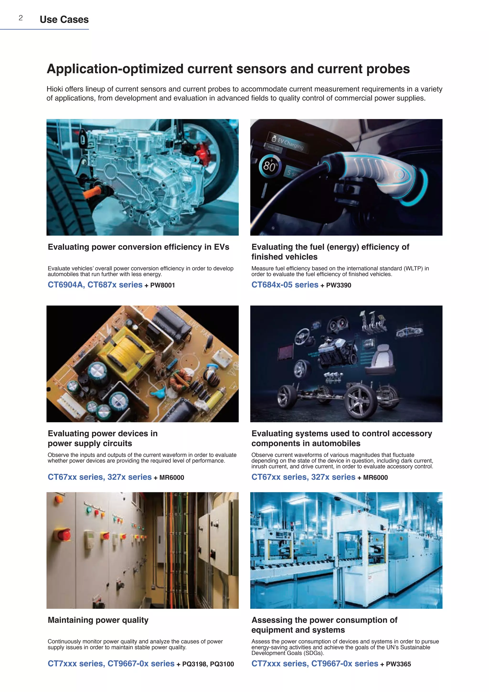
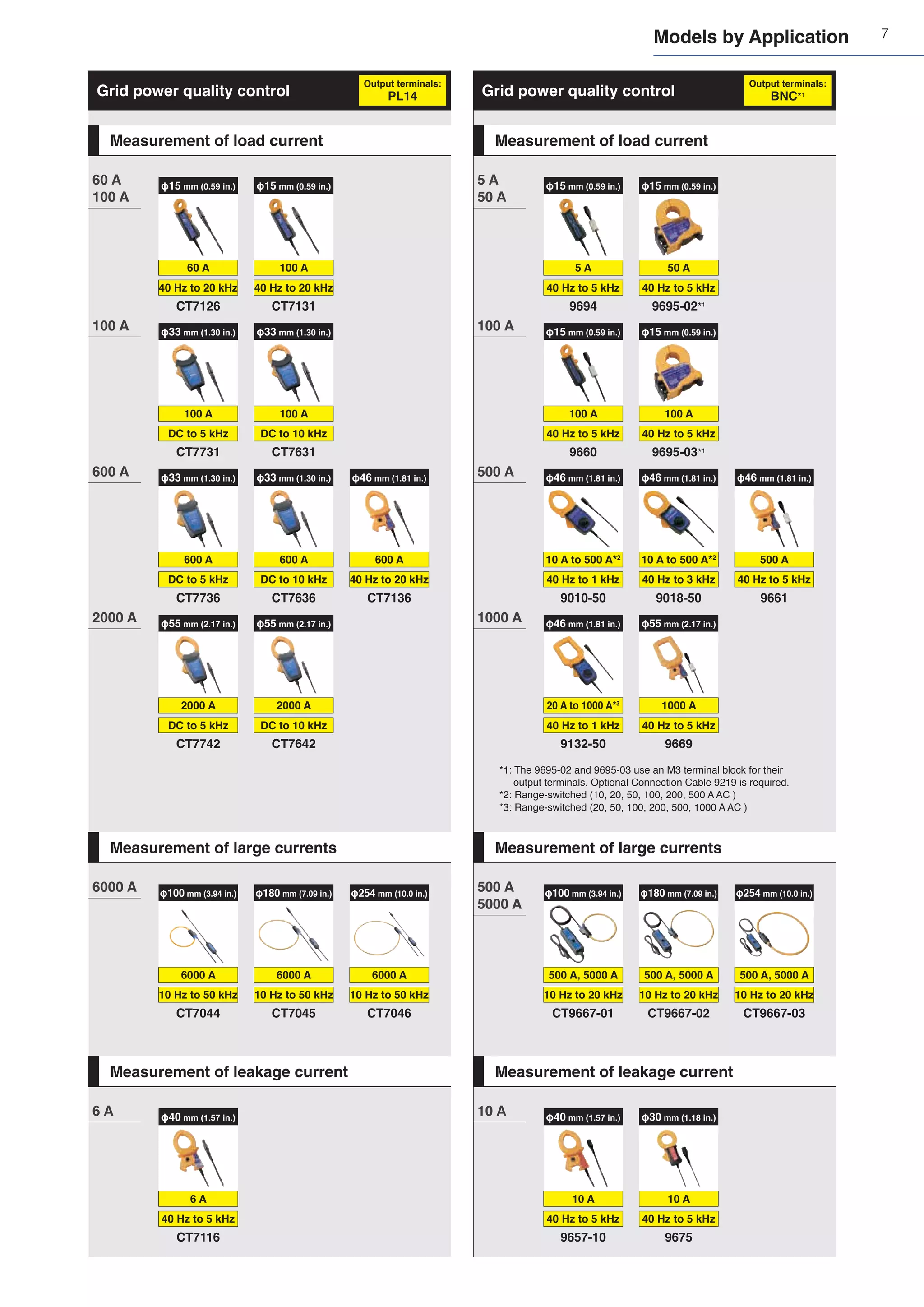
Effects of conductor position: stable, highly reproducible sensing
In general, speaking, the effects of conductor position increase with frequency. Since the position of the conductor inside the clamp core affects
the measurement accuracy, resulting the reproducibility of measurement reduces. Sensors are designed the effects of conductor position, highly
reproducible measurements are possible since conductor position does not affect measured values.
When using a sensor designed with the effects of conductor position,
measured values are not affected when the conductor’s position changes.
G
B
A
C
D
E
F
CT6904A Sensors designed without
accounting for conductor position
Conductor position
Gain
error*
[%
rdg]
deviation from center
-0.5
-0.4
-0.3
-0.2
-0.1
0.0
0.1
0.2
0.3
0.4
0.5
100 kHz
Conductor position
F G
A B C D E F G
A B C D E
-0.0100
Gain
error*
[%
rdg]
-0.0050
0.0000
0.0050
0.0100
60 Hz
Introduction to Current Sensors Designed for High-accuracy Measurement
Common-mode voltage rejection ratio: measuring current values accurately in noisy environments
In high-frequency measurement, sensors’ resistance to noise is critical. A sensor’s ability to remove noise is expressed by its common-mode rejection ratio
(CMRR). Sensors with a high CMRR reject more noise and therefore can make more accurate measurements.
For reactors, higher frequencies mean lower
current values. The image to the right shows
a waveform obtained by measuring reactor
current at high frequency along with variations in
current values that accompany variations in the
frequency.
Current
[A
rms]
1
0.1
0.01
0.001
Frequency [Hz]
0
1
0.1
0.01
0.001
500 k 1.0 M 1.5 M 2.0 M
Unable to generate accurate
measured values due to
the effects of noise
Unable to generate accurate
measured values due to
the effects of noise
Able to make accurate
measurements with
high noise resistance
Able to make accurate
measurements with
high noise resistance
Top: CT6904A CMRR 120 dB or greater (100 Hz); bottom: sensor with a low CMRR
Power
analyzer
Phase measurement accuracy and correction: accurately measuring power at low power factors
For typical current sensors, phase measurement accuracy is not defined. However, phase measurement precision is important in applications where power
must be measured with a high degree of accuracy. Power can be measured more accurately by selecting a current sensor for which phase measurement
accuracy is defined in the measurement band.
The power factor decreases in the high-frequency
range of the switching frequencies and other
frequency components. At low power factors,
phase error has a significant effect on power
measured values.
For typical sensors, phase error increases with frequency. Since Hioki has developed
both current sensors and the measuring instruments, current sensors’ phase
characteristics can be corrected by the instruments, allowing accurate power values to
be calculated.
Access the QR Code to view
the technical documentation
on phase correction.
At low power factors, phase error has
a significant effect on power error.
θ
P
𝑄
Power ratio ≈ 1 Power ratio ≈ 0
θ P
𝑄
Phase
error
Active
power error
-8
-6
-4
-2
0
2
Frequency [Hz]
Degree
[°]
10 100 1k 10k 100k 1M
Phase
Phase
when using
the Automatic Phase Correction
Example of the Automatic
Phase Correction for
the CT6904A AC/DC current sensor
Information stored in
the current sensors' internal memory
Phase shift Rated current
Sensor model Serial number
Automatic acquisition of
phase correction values
PW8001: Automatic Phase
Correction function
Power supplied
from instrument](https://image.slidesharecdn.com/seriessensorsprobese1-1zb-211217051801/75/HIOKI-Current-Series-sensors-probes_e1-1_zb-17-2048.jpg)
![20
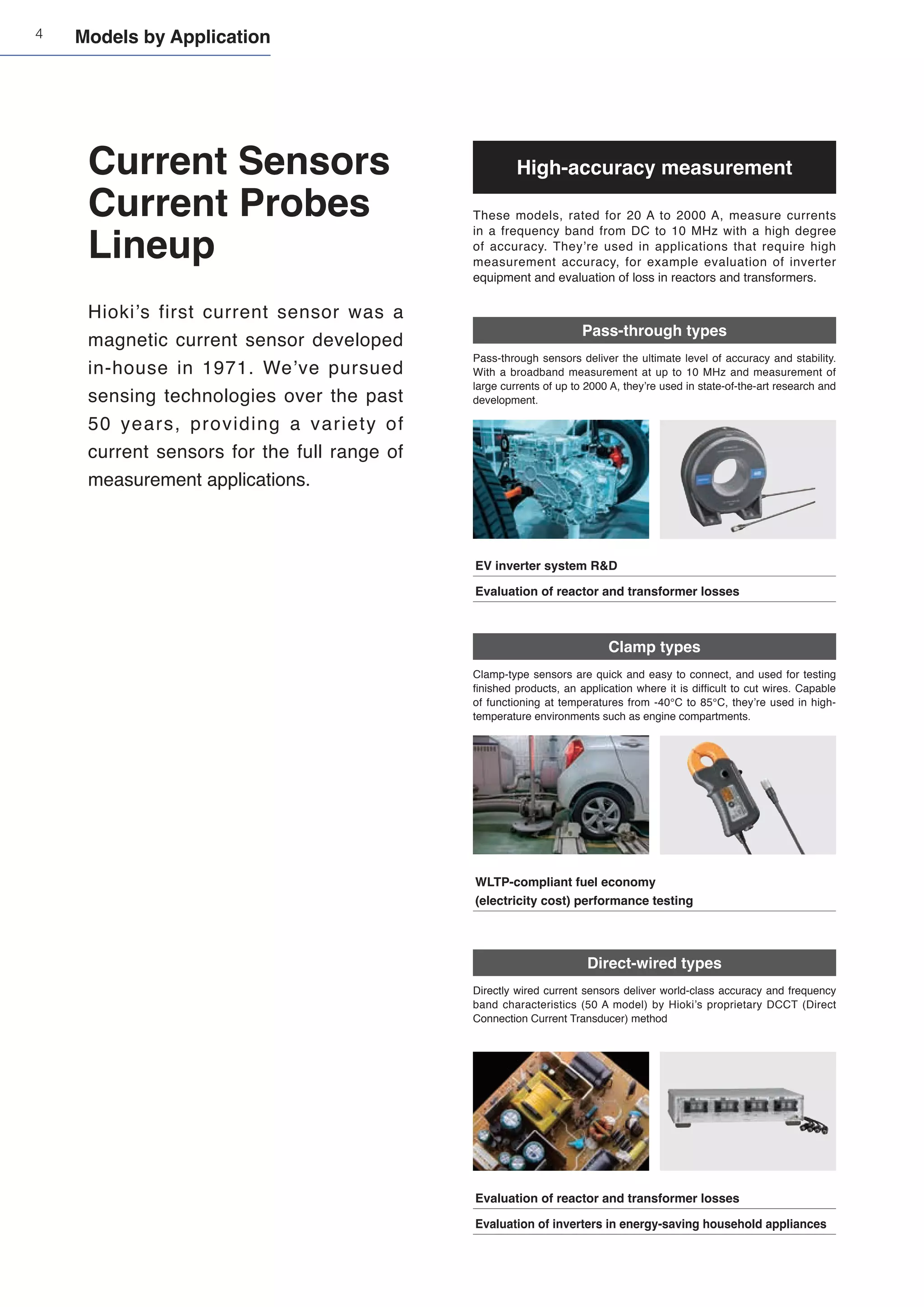
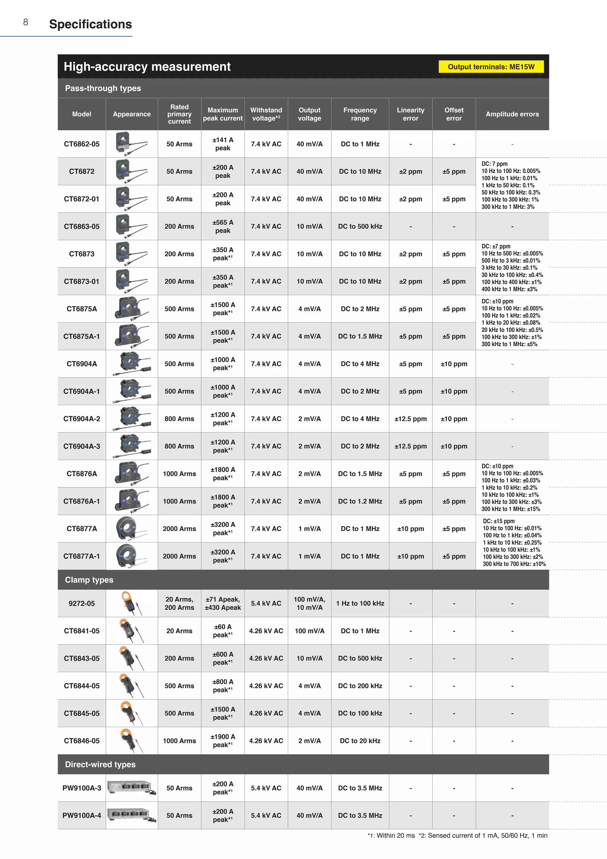
CT6862-05
Product warranty period: 3 years
Guaranteed accuracy period: 1 year
Rated current 50 A AC/DC
Frequency band DC to 1 MHz (-3 dB)
Diameter of measurable conductors Max. φ 24 mm (0.94 in.)
Output voltage 40 mV/A (= 2 V/50 A)
Operating temperature and
humidity range
-30°C to 85°C (-22°F to 185°F), 80% RH or less
(no condensation)
Storage temperature and
humidity range
-30°C to 85°C (-22°F to 185°F), 80% RH or less
(no condensation)
Maximum rated voltage to
ground
1000 V AC/DC (50/60 Hz), measurement category III,
anticipated transient overvoltage: 8000 V
Standards Safety: EN61010, EMC: EN61326
Cable length 3 m (9.84 ft.)
Dimensions
70 mm (2.76 in.) W × 100 mm (3.94 in.) H × 53 mm (2.09
in.) D (Excluding protruding parts and cables)
Weight Approx. 340 g (12.0 oz.)
Accuracy
Frequency
Amplitude
±(% of reading + % of full scale)
Phase
DC ±0.05% ±0.01% -
DC < f ≤ 16 Hz ±0.10% ±0.02% ±0.3°
16 Hz < f ≤ 400 Hz ±0.05% ±0.01% ±0.2°
400 Hz < f ≤ 1 kHz ±0.2% ±0.02% ±0.5°
1 kHz < f ≤ 5 kHz ±0.7% ±0.02% ±1.0°
5 kHz < f ≤ 10 kHz ±1% ±0.02% ±1.0°
10 kHz < f ≤ 50 kHz ±1% ±0.02% ± (0.5 + 0.1× f kHz)°
50 kHz < f ≤ 100 kHz ±2% ±0.05% ± (0.5 + 0.1× f kHz)°
100 kHz < f ≤ 300 kHz ±5% ±0.05% ± (0.5 + 0.1× f kHz)°
300 k Hz < f ≤ 700 kHz ±10% ±0.05% -
700 kHz < f < 1 MHz ±30% ±0.05% -
The values above are when the input is a sine wave, the conductor is in the center of the sensor opening, and the
measurement instrument’s input resistance is 1 MΩ or higher.
Amplitude accuracy:
defined at the rated value or less, or within the derating curve; DC < f < 5 Hz is the typical value by design.
Phase accuracy:
defined at the rated value or less, or within the derating curve; DC < f <10 Hz is the typical value by design.
Temperature and humidity
range for guaranteed accuracy
0°C to 40°C (32°F to 104°F), 80% RH or less
Effect of temperature
In ranges from -30°C to 0°C (-22°F to 32°F) and
40°C to 85°C (104°F to 185°F)
Amplitude sensitivity: ±0.005% rdg./°C or less
Offset voltage: ±0.005% f.s./°C or less
Effect of common mode voltage 0.05% f.s. or less (1000 Vrms, DC to 100 Hz)
Maximum
input
current
[Arms]
Frequency [Hz]
Frequency derating
40
60
0
20
80
100
120
DC 1 10 100 1k 10k 100k 1M
DC
Gain
[dB]
Frequency [Hz]
Frequency characteristics (example of typical characteristics)
-10
-8
-6
-4
-2
0
2
1 10 100 1k 10k 100k 1M
Phase
[°]
-30
-20
-10
0
10
20
30
Gain
Phase
Phase (corrected)
CT6872
CT6872-01
Product warranty period: 3 years
Guaranteed accuracy period: 1 year
Rated current 50 A AC/DC
Frequency band DC to 10 MHz (-3 dB)
Diameter of measurable conductors Max. φ 24 mm (0.94 in.)
Accuracy
Frequency
Amplitude
±(% of reading + % of full scale)
Phase
DC ±0.03% ±0.002% -
DC < f ≤ 16 Hz ±0.1% ±0.01% ±0.1°
16 Hz < f ≤ 45 Hz ±0.05% ±0.01% ±0.08°
45 Hz < f ≤ 66 Hz ±0.03% ±0.007% ±0.05°
66 Hz < f ≤ 100 Hz ±0.04% ±0.01% ±0.1°
100 Hz < f ≤ 500 Hz ±0.06% ±0.01% ±0.15°
500 Hz < f ≤ 1 kHz ±0.1% ±0.01% ±0.4°
1 kHz < f ≤ 5 kHz ±0.15% ±0.02% ±0.4°
5 kHz < f ≤ 10 kHz ±0.15% ±0.02% ±0.5°
10 kHz < f ≤ 1 MHz (0.012 × f kHz)% + 0.05% ±(0.04 × f kHz)° ±0.1°
The values above are when the input is a sine wave, the measuring instrument has an input resistance of 1 MΩ
±10%, the voltage to ground is 0 V, there is no external magnetic field, and the conductor is in
the center of the sensor opening.
Amplitude accuracy: defined 110% f.s. or less, or within the derating curve; DC < f < 10 Hz is the value by design.
Phase accuracy: defined 110% f.s. or less, or within the derating curve; DC < f < 10 Hz is the value by design.
Add ±0.01% rdg. to the amplitude accuracy for input from 100% f.s. to 110% f.s.
The CT6872-01 adds a phase accuracy of ±(0.015 × f)° at a frequency of 1 kHz < f ≤ 1 MHz.
Temperature and humidity
range for guaranteed accuracy
23°C ±5°C (73.4°F ±41°F), 80% RH or less
Effect of temperature
In ranges from -40°C to 18°C (-40°F to 64.4°F) and
28°C to 85°C (82.4°F to 185°F)
Amplitude sensitivity: ±20 ppm of rdg./°C
Offset voltage: ±0.2 ppm of f.s./°C
Common-Mode
Rejection Ratio
(CMRR)
(effect on output voltage and common mode voltage)
150 dB or greater (DC to 1 kHz)
140 dB or greater (1 kHz to 10 kHz)
120 dB or greater (10 kHz to 100 kHz)
100 dB or greater (100 kHz to 1 MHz)
Linearity error ±2 ppm
Offset error ±5 ppm
Amplitude errors
DC: 7 ppm
10 Hz to 100 Hz: 0.005%
100 Hz to 1 kHz: 0.01%
1 kHz to 50 kHz: 0.1%
50 kHz to 100 kHz: 0.3%
100 kHz to 300 kHz: 1%
300 kHz to 1 MHz: 3%
NEW
Output voltage 40 mV/A (= 2 V / 50 A)
Operating temperature and
humidity range
-40°C to 85°C (-40°F to 185°F), 80% RH or less
(no condensation)
Storage temperature and
humidity range
-40°C to 85°C (-40°F to 185°F), 80% RH or less
(no condensation)
Maximum rated voltage to
ground
1000 V CAT III
Anticipated transient overvoltage: 8000 V
Standards Safety: EN61010, EMC: EN61326
Cable length
CT6872: 3 m (9.84 ft.)
CT6872-01: 10 m (32.81 ft.)
Dimensions
70 mm (2.76 in.) W × 110 mm (4.33 in.) H × 53 mm (2.09
in.) D (excluding protruding parts and cables)
Weight
CT6872: approx. 370 g (13.1 oz.)
CT6872-01: approx. 690 g (24.3 oz.)
0.7 A
0.7 A
100 A
100 A
75 A
75 A
55 A
55 A
Maximum
input
current
[Arms]
Frequency [Hz]
Frequency derating
0
20
40
60
80
100
120
DC 10 100 1k 10k 100k 1M 10M
-40°C (-40°F) ≤ TA ≤ 40°C (104°F) (1 minute)
-40°C (-40°F) ≤ TA ≤ 60°C (140°F) (continuous)
-40°C (-40°F) ≤ TA ≤ 85°C (185°F) (continuous)
TA: Ambient temperature
Gain
[dB]
Frequency [Hz]
Frequency characteristics (example of typical characteristics)
-10
-8
-6
-4
-2
0
2
10 100 1k 10k 100k 1M 10M
Phase
[
°]
-40
-30
-20
-10
0
10
20
Gain
Phase
Phase (corrected)](https://image.slidesharecdn.com/seriessensorsprobese1-1zb-211217051801/75/HIOKI-Current-Series-sensors-probes_e1-1_zb-20-2048.jpg)
![21
CT6863-05
Product warranty period: 3 years
Guaranteed accuracy period: 1 year
Rated current 200 A AC/DC
Frequency band DC to 500 kHz (-3 dB)
Diameter of measurable conductors Max. φ 24 mm (0.94 in.)
Output voltage 10 mV/A (= 2 V / 200 A)
Operating temperature and
humidity range
-30°C to 85°C (-22°F to 185°F), 80% RH or less
(no condensation)
Storage temperature and
humidity range
-30°C to 85°C (-22°F to 185°F), 80% RH or less
(no condensation)
Maximum rated voltage to
ground
1000 V AC/DC (50/60 Hz), measurement category III,
anticipated transient overvoltage: 8000 V
Standards Safety: EN61010, EMC: EN61326
Cable length 3 m (9.84 ft.)
Dimensions
70 mm (2.76 in.) W × 100 mm (3.94 in.) H × 53 mm (2.09
in.) D (excluding protruding parts and cables)
Weight Approx. 340 g (12.0 oz.)
Accuracy
Frequency
Amplitude
±(% of reading + % of full scale)
Phase
DC ±0.05% ±0.01% -
DC < f ≤ 16 Hz ±0.10% ±0.02% ±0.3°
16 Hz < f ≤ 400 Hz ±0.05% ±0.01% ±0.2°
400 Hz < f ≤ 1 kHz ±0.2% ±0.02% ±0.5°
1 kHz < f ≤ 5 kHz ±0.7% ±0.02% ±1.0°
5 kHz < f ≤ 10 kHz ±1% ±0.02% ±1.0°
10 kHz < f ≤ 50 kHz ±2% ±0.02% ± (0.5 + 0.1 × f kHz)°
50 kHz < f ≤ 100 kHz ±5% ±0.05% ± (0.5 + 0.1 × f kHz)°
100 kHz < f ≤ 300 kHz ±10% ±0.05% ± (0.5 + 0.1 × f kHz)°
300 kHz < f ≤ 500 kHz ±30% ±0.05% -
The values above are when the input is a sine wave, the conductor is in the center
of the sensor opening, and the measurement instrument’s input resistance is 1 MΩ or higher.
Amplitude accuracy: defined at the rated value or less, or within the derating curve;
DC < f < 5 Hz is the typical value by design.
Phase accuracy: defined at the rated value or less, or within the derating curve;
DC < f < 10 Hz is the typical value by design.
Temperature and humidity
range for guaranteed accuracy
0°C to 40°C (32°F to 104°F), 80% RH or less
Effect of temperature
In ranges from -30°C to 0°C (-22°F to 32°F) and
40°C to 85°C (104°F to 185°F)
Amplitude sensitivity: ±0.005% rdg./°C or less
Offset voltage: ±0.005% f.s./°C or less
Effect of common mode voltage 0.05% f.s. or less (1000 Vrms, DC to 100 Hz)
Maximum
input
current
[Arms]
Frequency [Hz]
Frequency derating
200
300
0
100
400
500
DC 1 10 100 1k 10k 100k 1M
DC
Gain
[dB]
Frequency [Hz]
Frequency characteristics (example of typical characteristics)
-10
-8
-6
-4
-2
0
2
1 10 100 1k 10k 100k 1M
Phase
[°]
-30
-20
-10
0
10
20
30
Gain
Phase
Phase (corrected)
CT6873
CT6873-01
Product warranty period: 3 years
Guaranteed accuracy period: 1 year
Rated current 200 A AC/DC
Frequency band DC to 10 MHz (-3 dB)
Diameter of measurable conductors Max. φ 24 mm (0.94 in.)
Output voltage 10 mV/A (= 2 V / 200 A)
Operating temperature and
humidity range
-40°C to 85°C (-40°F to 185°F), 80% RH or less
(no condensation)
Storage temperature and
humidity range
-40°C to 85°C (-40°F to 185°F), 80% RH or less
(no condensation)
Maximum rated voltage to
ground
1000 V CAT III
Anticipated transient overvoltage: 8000 V
Standards Safety: EN61010, EMC: EN61326
Cable length
CT6873: 3 m (9.84 ft.)
CT6873-01: 10 m (32.81 ft.)
Dimensions
70 mm (2.76 in.) W × 110 mm (4.33 in.) H × 53 mm (2.09
in.) D (excluding protruding parts and cables)
Weight
CT6873: approx. 370 g (13.1 oz.)
CT6873-01: approx. 690 g (24.3 oz.)
Accuracy
Frequency
Amplitude
±(% of reading + % of full scale)
Phase
DC ±0.03% ±0.002% -
DC < f ≤ 16 Hz ±0.1% ±0.01% ±0.1°
16 Hz < f ≤ 45 Hz ±0.05% ±0.01% ±0.08°
45 Hz < f ≤ 66 Hz ±0.03% ±0.007% ±0.05°
66 Hz < f ≤ 100 Hz ±0.04% ±0.01% ±0.1°
100 Hz < f ≤ 500 Hz ±0.05% ±0.01% ±0.15°
500 Hz < f ≤ 3 kHz ±0.1% ±0.01% ±0.4°
3 kHz < f ≤ 5 kHz ±0.2% ±0.02% ±0.4°
5 kHz < f ≤ 10 kHz ±0.2% ±0.02% ±0.5°
10 kHz < f ≤ 1 MHz (0.018 × f kHz)% + 0.05% ±(0.04 × f kHz)° ±0.1°
The values above are when the input is a sine wave, the measuring instrument has an input resistance of 1 MΩ
±10%, the voltage to ground is 0 V, there is no external magnetic field, and the conductor is in
the center of the sensor opening.
Amplitude accuracy: defined 110% f.s. or less, or within the derating curve; DC < f < 10 Hz is the value by design.
Phase accuracy: defined 110% f.s. or less, or within the derating curve; DC < f < 10 Hz is the value by design.
Add ±0.01% rdg. to the amplitude accuracy for input from 100% f.s. to 110% f.s.
The CT6873-01 adds a phase accuracy of ±(0.015 × f)° at a frequency of 1 kHz < f ≤ 1 MHz.
Temperature and humidity
range for guaranteed accuracy
23°C ±5°C (73.4°F ±41°F), 80% RH or less
Effect of temperature
In ranges from -40°C to 18°C (-40°F to 64.4°F) and
28°C to 85°C (82.4°F to 185°F)
Amplitude sensitivity: ±15 ppm of rdg./°C
Offset voltage: ±0.1 ppm of f.s./°C
Common-Mode
Rejection Ratio
(CMRR)
(effect on output voltage and common mode voltage)
150 dB or greater (DC to 1 kHz)
140 dB or greater (1 kHz to 10 kHz)
120 dB or greater (10 kHz to 100 kHz)
100 dB or greater (100 kHz to 1 MHz)
Linearity errors ±2 ppm
Offset error ±5 ppm
Amplitude error
DC: ±7 ppm
10 Hz to 500 Hz: ±0.005%
500 Hz to 3 kHz: ±0.01%
3 kHz to 30 kHz: ±0.1%
30 kHz to 100 kHz: ±0.4%
100 kHz to 400 kHz: ±1%
400 kHz to 1 MHz: ±3%
DC 400 A
DC 400 A
300 A
300 A
220 A
220 A
0.7 A
0.7 A
Maximum
input
current
[Arms]
Frequency [Hz]
Frequency derating
0
100
200
300
400
500
DC 10 100 1k 10k 100k 1M 10M
-40°C (-40°F) ≤ TA ≤ 40°C (104°F) (1 minute)
-40°C (-40°F) ≤ TA ≤ 60°C (140°F) (continuous)
-40°C (-40°F) ≤ TA ≤ 85°C (185°F) (continuous)
TA: Ambient temperature
NEW
Gain
[dB]
Frequency [Hz]
Frequency characteristics (example of typical characteristics)
-10
-8
-6
-4
-2
0
2
10 100 1k 10k 100k 1M 10M
Phase
[
°]
-40
-30
-20
-10
0
10
20
Gain
Phase
Phase (corrected)](https://image.slidesharecdn.com/seriessensorsprobese1-1zb-211217051801/75/HIOKI-Current-Series-sensors-probes_e1-1_zb-21-2048.jpg)
![22
CT6904A
CT6904A-1
(CT6904A-1: build-to-order product)
Product warranty period: 3 years
Guaranteed accuracy period: 1 year
Rated current 500 A AC/DC
Frequency band CT6904A: DC to 4 MHz (±3 dB)
CT6904A-1: DC to 2 MHz (±3 dB)
Diameter of measurable conductors Max. φ 32 mm (1.25 in.)
Accuracy
Frequency
Amplitude
±(% of reading + % of full scale)
Phase
DC ±0.025% ±0.007% -
DC < f < 16 Hz ±0.2% ±0.02% ±0.1°
16 Hz ≤ f < 45 Hz ±0.1% ±0.02% ±0.1°
45 Hz ≤ f ≤ 65 Hz ±0.02% ±0.007% ±0.08°
65 Hz < f ≤ 850 Hz ±0.05% ±0.007% ±0.12°
850 Hz < f ≤ 1 kHz ±0.1% ±0.01% ±0.4°
1 kHz < f ≤ 5 kHz ±0.4% ±0.02% ±0.4°
5 kHz < f ≤ 10 kHz ±0.4% ±0.02% ±(0.08 × f kHz)°
10 kHz < f ≤ 50 kHz ±1% ±0.02% ±(0.08 × f kHz)°
50 kHz < f ≤ 100 kHz ±1% ±0.05% ±(0.08 × f kHz)°
100 kHz < f ≤ 300 kHz ±2% ±0.05% ±(0.08 × f kHz)°
300 kHz < f ≤ 1 MHz ±5% ±0.05% ±(0.08 × f kHz)°
· Amplitude accuracy and phase accuracy: defined 110% f.s. or less, or within the derating curve
(continuous input at an ambient temperature of 50°C); DC < f < 10 Hz is the value by design.
· Add ±0.01% rdg. to the amplitude accuracy for input from 100% f.s. to 110% f.s.
· For the CT6904A-1, add the following for frequencies of
50 kHz < f ≤ 1 MHz.(the frequency band is 2 MHz ±3 dB):
Amplitude accuracy: ±(0.015 × f)% rdg.
Output voltage 4 mV/A (= 2 V / 500 A)
Operating temperature and
humidity range
-10°C to 50°C (-14°F to 122°F), 80% RH or less (no
condensation)
Storage temperature and
humidity range
-20°C to 60°C (-4°F to 140°F), 80% RH or less
(no condensation)
Maximum rated voltage to
ground
1000 V CAT III
Anticipated transient overvoltage: 8000 V
Standards Safety: EN61010, EMC: EN61326
Cable length
CT6904A: 3 m (9.84 ft.) (including relay box))
CT6904A-1: 10 m (32.81 ft.) (including relay box)
Dimensions
139 mm (5.47 in.) W × 120 mm (4.72 in.) H × 52 mm (2.05
in.) D (excluding protrusions and cables)
Weight
CT6904A: approx. 1.05 kg (37.0 oz.)
CT6904A-1: approx. 1.35 kg (47.6 oz.)
Temperature and humidity
range for guaranteed accuracy
23°C ±5°C (73°F ±9°F), 80% RH or less
Effect of temperature
In ranges from -10°C to 18°C (14°F to 64.4°F) or 28°C to
50°C (82.4°F to 122°F)
Amplitude sensitivity: ±20 ppm of of reading / °C
Offset voltage: ±1 ppm of full scale / °C
Phase: ±0.01°/°C
Common-Mode
Rejection Ratio
(CMRR)
(effect on output voltage and common mode voltage)
140 dB or greater (50/60 Hz)
120 dB or greater (100 kHz)
Linearity error ±5 ppm
Offset error ±10 ppm
DC
Maximum
input
current
[Arms]
Frequency [Hz]
Frequency derating
10
100
1k
1 10 100 1k 10k 100k 1M 10M
600 A
550 A
1 min. at an ambient
temperature of 50°C (122°F)
Continuous input at an ambient
temperature of 30°C (86°F)
Continuous input at an ambient
temperature of 50°C (122°F)
DC
Gain
[dB]
Phase
[°]
Frequency [Hz]
Frequency characteristics (example of typical characteristics)
-10
-8
-6
-4
-2
0
2
-8
-6
-4
-2
0
2
4
1 10 100 1k 10k 100k 1M 10M
Gain
Phase
Phase (corrected)
Output voltage 4 mV/A (= 2 V / 500 A)
Operating temperature and
humidity range
-40°C to 85°C (-40°F to 185°F), 80% RH or less
(no condensation)
Storage temperature and
humidity range
-40°C to 85°C (-40°F to 185°F), 80% RH or less
(no condensation)
Maximum rated voltage to
ground
1000 V CAT III
Anticipated transient overvoltage: 8000 V
Standards Safety: EN61010, EMC: EN61326
Cable length
CT6875A: 3 m (9.84 ft.)
CT6875A-1: 10 m (32.81 ft.)
Dimensions
160 mm (6.30 in.) W × 112 mm (4.41 in.) H × 50 mm (1.97
in.) D (excluding protruding parts and cables)
Weight
CT6875A: approx. 0.8 kg (28.2 oz.)
CT6875A-1: approx. 1.1 kg (38.8 oz.)
Accuracy
Frequency
Amplitude
±(% of reading + % of full scale)
Phase
DC ±0.04% ±0.008% -
DC < f < 16 Hz ±0.1% ±0.02% ±0.1°
16 Hz ≤ f < 45 Hz ±0.05% ±0.01% ±0.1°
45 Hz ≤ f ≤ 66 Hz ±0.04% ±0.008% ±0.08°
66 Hz < f ≤ 100 Hz ±0.05% ±0.01% ±0.1°
100 Hz < f ≤ 500 Hz ±0.1% ±0.02% ±0.2°
500 Hz < f ≤ 1 kHz ±0.2% ±0.02% ±0.4°
1 kHz < f ≤ 5 kHz ±0.4% ±0.02% ±0.5°
5 kHz < f ≤ 10 kHz ±0.4% ±0.02% ±(0.1 × f kHz)°
10 kHz < f ≤ 50 kHz ±1.5% ±0.05% ±(0.1 × f kHz)°
50 kHz < f ≤ 100 kHz ±2.5% ±0.05% ±(0.1 × f kHz)°
100 kHz < f ≤ 1 MHz ±(0.025 × f kHz)% ±0.05% ±(0.1 × f kHz)°
Amplitude accuracy: defined 110% f.s. or less, or within the derating curve;
DC < f < 10 Hz is the value by design.
Add ±0.01% rdg. to the amplitude accuracy for input from 100% f.s. to 110% f.s.
· For the CT6875A-1, add the following for frequencies of
1 kHz < f ≤ 1 MHz (the frequency band is 1.5 MHz ±3 dB):
Amplitude accuracy: ±(0.005 × f kHz)% rdg., Phase accuracy: ±(0.015 × f kHz)°
Temperature and humidity
range for guaranteed accuracy
0°C to 40°C (32°F to 104°F), 80% RH or less
Effect of temperature
In ranges from -40°C to 0°C (-40°F to 32°F) and
40°C to 85°C (104°F to 185°F)
Amplitude sensitivity: ±20 ppm of reading / °C
Offset voltage: ±1 ppm of full scale / °C
Common-Mode
Rejection Ratio
(CMRR)
(effect on output voltage and common mode voltage)
140 dB or greater (50/60 Hz)
120 dB or greater (100 kHz)
Linearity error ±5 ppm
Offset error ±5 ppm
Amplitude error
DC: ±10 ppm
10 Hz to 100 Hz: ±0.005%
100 Hz to 1 kHz: ±0.02%
1 kHz to 20 kHz: ±0.08%
20 kHz to 100 kHz: ±0.5%
100 kHz to 300 kHz: ±1%
300 kHz to 1 MHz: ±5%
CT6875A
CT6875A-1
Product warranty period: 3 years
Guaranteed accuracy period: 1 year
Rated current 500 A AC/DC
Frequency band CT6875A: DC to 2 MHz (±3 dB)
CT6875A-1: DC to 1.5 MHz (±3 dB)
Diameter of measurable conductors Max. φ 36 mm (1.41 in.)
Maximum
input
current
[Arms]
Frequency [Hz]
Frequency derating
10
100
1k
2k
DC 10 100 1k 10k 100k 1M
-40°C (-40°F) ≤ TA ≤ 40°C (104°F) (1 minute)
-40°C (-40°F) ≤ TA ≤ 60°C (140°F) (continuous)
-40°C (-40°F) ≤ TA ≤ 85°C (185°F) (continuous)
TA: Ambient temperature
DC
Gain
[dB]
Frequency [Hz]
Frequency characteristics (example of typical characteristics)
-10
-8
-6
-4
-2
0
2
1 10 100 1k 10k 100k 1M
Phase
[°]
-40
-30
-20
-10
0
10
20
Gain
Phase
Phase (corrected)](https://image.slidesharecdn.com/seriessensorsprobese1-1zb-211217051801/75/HIOKI-Current-Series-sensors-probes_e1-1_zb-22-2048.jpg)
![23
CT6904A-2
CT6904A-3
(Build-to-order product)
Product warranty period: 3 years
Guaranteed accuracy period: 1 year
Rated current 800 A AC/DC
Frequency band CT6904A-2: DC to 4 MHz (±3 dB)
CT6904A-3: DC to 2 MHz (±3 dB)
Diameter of measurable conductors Max. φ 32 mm (1.25 in.)
Output voltage 2 mV/A (= 2 V / 1000 A)
Operating temperature and
humidity range
-10°C to 50°C (-14°F to 122°F), 80% RH or less (no
condensation)
Storage temperature and
humidity range
-20°C to 60°C (-4°F to 140°F), 80% RH or less
(no condensation)
Maximum rated voltage to
ground
1000 V CAT III
Anticipated transient overvoltage: 8000 V
Standards Safety: EN61010, EMC: EN61326
Cable length
CT6904A-2: 3 m (9.84 ft.) (including relay box)
CT6904A-3: 10 m (32.81 ft.) (including relay box)
Dimensions
139 mm (5.47 in.) W × 120 mm (4.72 in.) H × 52 mm (2.05
in.) D (excluding protrusions and cables)
Weight
CT6904A-2: approx. 1.15 kg (40.6 oz.)
CT6904A-3: approx. 1.45 kg (51.1 oz.)
Accuracy
Frequency
Amplitude
±(% of reading + % of full scale)
Phase
DC ±0.030% ±0.009% -
DC < f < 16 Hz ±0.2% ±0.025% ±0.1°
16 Hz ≤ f < 45 Hz ±0.1% ±0.025% ±0.1°
45 Hz ≤ f ≤ 65 Hz ±0.025% ±0.009% ±0.08°
65 Hz < f ≤ 850 Hz ±0.05% ±0.009% ±0.12°
850 Hz < f ≤ 1 kHz ±0.1% ±0.013% ±0.4°
1 kHz < f ≤ 5 kHz ±0.4% ±0.025% ±0.4°
5 kHz < f ≤10 kHz ±0.4% ±0.025% ±(0.08 × f kHz)°
10 kHz < f ≤ 50 kHz ±1% ±0.025% ±(0.08 × f kHz)°
50 kHz < f ≤ 100 kHz ±1% ±0.063% ±(0.08 × f kHz)°
100 kHz < f ≤ 300 kHz ±2% ±0.063% ±(0.08 × f kHz)°
300 kHz < f ≤ 1 MHz ±5% ±0.063% ±(0.08 × f kHz)°
Amplitude accuracy and phase accuracy are specified by the following conditions:
· Rated value or less
· At 100Hz or more and within the range of "Continuous input at an ambient temperature of
50°C (122°F) " described in the frequency derating graph below
· For the CT6904A-3, add the following for frequencies of 50 kHz < f ≤ 1 MHz
(frequency band is 2 MHz ±3):
Amplitude accuracy: ±(0.015 × f)% rdg.
Temperature and humidity
range for guaranteed
accuracy
23°C ±5°C (73°F ±9°F), 80% RH or less
Effect of temperature
In ranges from -10°C to 18°C (14°F to 64.4°F) or 28°C to
50°C (82.4°F to 122°F)
Amplitude sensitivity: ± 50 ppm of reading / °C
Offset voltage: ±5 ppm of full scale / °C
Phase: ±0.01° / °C
Common-Mode
Rejection Ratio
(CMRR)
(effect on output voltage and common mode voltage)
140 dB or greater (50/60 Hz)
120 dB or greater (100 kHz)
Linearity error ±12.5 ppm
Offset error ±10 ppm
DC
Maximum
input
current
[Arms]
Frequency [Hz]
Frequency derating
10
100
1k
1 10 100 1k 10k 100k 1M 10M
800 A
750 A
1 min. at an ambient
temperature of 50°C (122°F)
Continuous input at an ambient
temperature of 30°C (86°F)
Continuous input at an ambient
temperature of 50°C (122°F)
DC
Gain
[dB]
Frequency [Hz]
Frequency characteristics (example of typical characteristics)
-10
-8
-6
-4
-2
0
2
1 10 100 1k 10k 100k 1M 10M
Phase
[°]
-8
-6
-4
-2
0
2
4
Gain
Phase
Phase (corrected)
Output voltage 2 mV/A (= 2 V / 1000 A)
Operating temperature and
humidity range
-40°C to 85°C (-40°F to 185°F), 80% RH or less
(no condensation)
Storage temperature and
humidity range
-40°C to 85°C (-40°F to 185°F), 80% RH or less
(no condensation)
Maximum rated voltage to
ground
1000 V CAT III
Anticipated transient overvoltage: 8000 V
Standards Safety: EN61010, EMC: EN61326
Cable length
CT6876A: 3 m (9.84 ft.)
CT6876A-1: 10 m (32.81 ft.)
Dimensions
160 mm (6.30 in.) W × 112 mm (4.41 in.) H × 50 mm (1.97
in.) D (excluding protruding parts and cables)
Weight
CT6876A: approx. 0.95 kg (33.5 oz.)
CT6876A-1: approx. 1.25 kg (44.1 oz.)
Accuracy
Frequency
Amplitude
±(% of reading + % of full scale)
Phase
DC ±0.04% ±0.008% -
DC < f < 16 Hz ±0.1% ±0.02% ±0.1°
16 Hz ≤ f < 45 Hz ±0.05% ±0.01% ±0.1°
45 Hz ≤ f ≤ 66 Hz ±0.04% ±0.008% ±0.08°
66 Hz < f ≤ 100 Hz ±0.05% ±0.01% ±0.1°
100 Hz < f ≤ 500 Hz ±0.1% ±0.02% ±0.2°
500 Hz < f ≤ 1 kHz ±0.2% ±0.02% ±0.4°
1 kHz < f ≤ 5 kHz ±0.5% ±0.02% ±0.5°
5 kHz < f ≤ 10 kHz ±0.5% ±0.02% ±(0.1 × f kHz)°
10 kHz < f ≤ 50 kHz ±2% ±0.05% ±(0.1 × f kHz)°
50 kHz < f ≤ 100 kHz ±3% ±0.05% ±(0.1 × f kHz)°
100 kHz < f ≤ 1 MHz ±(0.03 × f kHz)% ±0.05% ±(0.1 × f kHz)°
· Amplitude accuracy and phase accuracy: defined 110% f.s. or less or within the derating curve;
DC < f < 10 Hz is the value by design
· Add ±0.01% rdg. to the amplitude accuracy for input from 100% f.s. to 110% f.s.
· For the CT6876A-1, add the following for frequencies of 1 kHz < f ≤ 1 MHz
(the frequency band is 1.2 MHz ±3 dB):
Amplitude accuracy: ±(0.005 × f kHz)% rdg., Phase accuracy: ±(0.015 × f kHz)°
Temperature and humidity
range for guaranteed
accuracy
0°C to 40°C (32°F to 104°F), 80% RH or less
Effect of temperature
In ranges from -40°C to 0°C (-40°F to 32°F) and
40°C to 85°C (104°F to 185°F)
Amplitude sensitivity: ±20 ppm of reading / °C
Offset voltage: ±1 ppm of full scale / °C
Common-Mode
Rejection Ratio
(CMRR)
(effect on output voltage and common mode voltage)
140 dB or greater (50/60 Hz)
120 dB or greater (100 kHz)
Linearity error ±5 ppm
Offset error ±5 ppm
Amplitude error
DC: ±10 ppm
10 Hz to 100 Hz: ±0.005%
100 Hz to 1 kHz: ±0.03%
1 kHz to 10 kHz: ±0.2%
10 kHz to 100 kHz: ±1%
100 kHz to 300 kHz: ±3%
300 kHz to 1 MHz: ±15%
CT6876A
CT6876A-1
Product warranty period: 3 years
Guaranteed accuracy period: 1 year
Rated current 1000 A AC/DC
Frequency band CT6876A: DC to 1.5 MHz (±3 dB)
CT6876A-1: DC to 1.2 MHz (±3 dB)
Diameter of measurable conductors Max. φ 36 mm (1.41 in.)
100
1k
2k
-40°C (-40°F) ≤ TA ≤ 40°C (104°F) (1 minute)
-40°C (-40°F) ≤ TA ≤ 60°C (140°F) (continuous)
-40°C (-40°F) ≤ TA ≤ 85°C (185°F) (continuous)
TA: Ambient temperature
Maximum
input
current
[Arms]
Frequency [Hz]
Frequency derating
10
DC 10 100 1k 10k 100k 1M
DC
Gain
[dB]
Frequency [Hz]
Frequency characteristics (example of typical characteristics)
-10
-8
-6
-4
-2
0
2
1 10 100 1k 10k 100k 1M
Phase
[°]
-40
-30
-20
-10
0
10
20
Gain
Phase
Phase (corrected)](https://image.slidesharecdn.com/seriessensorsprobese1-1zb-211217051801/75/HIOKI-Current-Series-sensors-probes_e1-1_zb-23-2048.jpg)
![24
Output voltage 40 mV/A (= 2 V / 50 A)
Operating temperature and
humidity range
0°C to 40°C (32°F to 104°F), 80% RH or less
(no condensation)
Storage temperature and
humidity range
-10°C to 50°C (14°F to 122°F), 80% RH or less
(no condensation)
Maximum rated voltage to
ground
600 V CAT III, 1000 V CAT II
Anticipated transient overvoltage: 6000 V
Standards Safety: EN 61010, EMC: EN 61326 Class A
Cable length 0.8 m (2.62 ft.)
Dimensions
430 mm (16.9 in.) W × 88 mm (3.46 in.) H × 260 mm
(10.23 in.) D
Weight
PW9100A-3: approx. 3.7 kg (130.5 oz.)
PW9100A-4: approx. 4.3 kg (151.7 oz.)
Accuracy
Frequency
Amplitude
±(% of reading + % of full scale)
Phase
DC ±0.02% ±0.007% -
DC < f < 30 Hz ±0.1% ±0.02% ±0.3°
30 Hz ≤ f < 45 Hz ±0.1% ±0.02% ±0.1°
45 Hz ≤ f ≤ 65 Hz ±0.02% ±0.005% ±0.1°
65 Hz < f ≤ 500 Hz ±0.1% ±0.01% ±0.12°
500 Hz < f ≤ 1 kHz ±0.1% ±0.01% ±0.5°
1 kHz < f ≤ 5 kHz ±0.5% ±0.02% ±0.5°
5 kHz < f ≤ 20 kHz ±1% ±0.02% ±1°
20 kHz < f ≤ 50 kHz ±1% ±0.02% ±(0.05 × f kHz)°
50 kHz < f ≤ 100 kHz ±2% ±0.05% ±(0.06 × f kHz)°
100 kHz < f ≤ 300 kHz ±5% ±0.05% ±(0.06 × f kHz)°
300 kHz < f ≤ 700 kHz ±5% ±0.05% ±(0.07 × f kHz)°
700 kHz < f ≤ 1 MHz ±10% ±0.05% ±(0.07 × f kHz)°
· Amplitude accuracy and phase accuracy: defined within the accuracy guarantee range shown in
the derating figure below; DC < f < 10 Hz is the value by design.
· Add ±0.01% rdg. to the amplitude accuracy for input from 100% f.s. to 110% f.s.
Temperature and humidity
range for guaranteed
accuracy
23°C ±5°C (73°F ±9°F), 80% RH or less
Effect of temperature
In ranges from 0°C to 18°C (32°F to 64°F) and
28°C to 40°C (82°F to 104°F)
Amplitude sensitivity: ±20 ppm of reading /°C
Offset voltage: ±1 ppm of full scale / °C
Phase: ±0.01° / °C
Common-Mode
Rejection Ratio
(CMRR)
(effect on output voltage and common mode voltage)
120 dB or greater (50/60 Hz, 100 kHz)
PW9100A-3
PW9100A-4
Product warranty period: 3 years
Guaranteed accuracy period: 1 year
Rated current 50 A AC/DC
Frequency band DC to 3.5 MHz
Input and measurement method
Measurement terminals
Isolated input, DCCT* input
Terminal block M6 screws
Maximum
input
current
[Arms]
Frequency [Hz]
Frequency derating
0
1
10
50
100
DC 1 10 100 1k 10k 100k 10M
1M
Frequency derating
Guaranteed accuracy range
30 kHz, 60 A
10 MHz, 0.7 A
100 kHz, 30 A
DC
Gain
[dB]
Frequency [Hz]
Frequency characteristics (example of typical characteristics)
-10
-8
-6
-4
-2
0
2
1 10 100 1k 10k 100k 1M 10M
Phase
[°]
-8
-6
-4
-2
0
2
4
Gain
Phase
Phase (corrected)
Output voltage 1 mV/A (= 2 V / 2000 A)
Operating temperature and
humidity range
-40°C to 85°C (-40°F to 185°F), 80% RH or less
(no condensation)
Storage temperature and
humidity range
-40°C to 85°C (-40°F to 185°F), 80% RH or less
(no condensation)
Maximum rated voltage to
ground
1000 V CAT III
Anticipated transient overvoltage: 8000 V
Standards Safety: EN61010, EMC: EN61326
Cable length
CT6877A: 3 m (9.84 ft.)
CT6877A-1: 10 m (32.81 ft.)
Dimensions
229 mm (9.02 in.) W × 232 mm (9.13 in.) H × 112 mm
(4.41 in.) D (excluding protruding parts and cables)
Weight
CT6877A: approx. 5 kg (176.4 oz.)
CT6877A-1: approx. 5.3 kg (187.0 oz.)
Accuracy
Frequency
Amplitude
±(% of reading + % of full scale)
Phase
DC ±0.04% ±0.008% -
DC < f < 16 Hz ±0.1% ±0.02% ±0.1°
16 Hz ≤ f < 45 Hz ±0.05% ±0.01% ±0.1°
45 Hz ≤ f ≤ 66 Hz ±0.04% ±0.008% ±0.08°
66 Hz < f ≤ 100 Hz ±0.05% ±0.01% ±0.1°
100 Hz < f ≤ 500 Hz ±0.1% ±0.02% ±0.2°
500 Hz < f ≤ 1 kHz ±0.2% ±0.02% ±0.4°
1 kHz < f ≤ 5 kHz ±0.5% ±0.02% ± (0.3 + 0.1 × f kHz)°
5 kHz < f ≤ 10 kHz ±0.5% ±0.02% ± (0.3 + 0.1 × f kHz)°
10 kHz < f ≤ 50 kHz ±1.5% ±0.05% ± (0.3 + 0.1 × f kHz)°
50 kHz < f ≤ 100 kHz ±2.5% ±0.05% ± (0.3 + 0.1 × f kHz)°
100 kHz < f ≤ 700 kHz ±(0.025 × f)% ±0.05% ± (0.3 + 0.1 × f kHz)°
· Amplitude accuracy and phase accuracy: defined 110% f.s. or less, or within the derating curve,
DC < f < 10 Hz is the value by design
· Add ±0.01% rdg. to the amplitude accuracy for input from 100% f.s. to 110% f.s.
· For the CT6877A-1, add the following for frequencies of 1 kHz < f ≤ 700 kHz:
Amplitude accuracy: ±(0.005 × f)% rdg., Phase accuracy: ±(0.015 × f)°
Temperature and humidity
range for guaranteed
accuracy
0°C to 40°C (32°F to 104°F), 80% RH or less
Effect of temperature
In ranges from -40°C to 0°C (-40°F to 32°F) and
40°C to 85°C (104°F to 185°F)
Amplitude sensitivity: ±15 ppm of reading / °C
Offset voltage: ±0.5 ppm of full scale / °C
Common-Mode
Rejection Ratio
(CMRR)
(effect on output voltage and common mode voltage)
140 dB or greater (50/60 Hz)
120 dB or greater (100 kHz)
Linearity error ±10 ppm
Offset error ±5 ppm
Amplitude error
DC: ±15 ppm
10 Hz to 100 Hz: ±0.01%
100 Hz to 1 kHz: ±0.04%
1 kHz to 10 kHz: ±0.25%
10 kHz to 100 kHz: ±1%
100 kHz to 300 kHz: ±2%
300 kHz to 700 kHz: ±10%
CT6877A
CT6877A-1
Product warranty period: 3 years
Guaranteed accuracy period: 1 year
Rated current 2000 A AC/DC
Frequency band DC to 1 MHz
Diameter of measurable conductors Max. φ 80 mm (3.14 in.)
Maximum
input
current
[Arms]
Frequency [Hz]
Frequency derating
10
100
1k
2k
3k
DC 1 10 100 1k 10k 100k 1M
TA: Ambient temperature
-40°C (-40°F) ≤ TA ≤ 60°C (140°F) (continuous)
-40°C (-40°F) ≤ TA ≤ 85°C (185°F) (continuous)
DC
Gain
[dB]
Frequency [Hz]
Frequency characteristics (example of typical characteristics)
-10
-8
-6
-4
-2
0
2
1 10 100 1k 10k 100k 1M
Phase
[°]
-40
-30
-20
-10
0
10
20
Gain
Phase
Phase (corrected)
*Direct Connection Current Transducer](https://image.slidesharecdn.com/seriessensorsprobese1-1zb-211217051801/75/HIOKI-Current-Series-sensors-probes_e1-1_zb-24-2048.jpg)
![25
Output voltage 100 mV/A (= 2 V / 20 A)
Measurable conductors Insulated conductor
Operating temperature and
humidity range
-40°C to 85°C (-40°F to 185°F), 80% RH or less
(no condensation)
Storage temperature and
humidity range
-40°C to 85°C (-40°F to 185°F), 80% RH or less
(no condensation)
Withstand voltage
4260 V AC
Withstand test current of 1 mA, 50/60 Hz, 1 min.,
between jaws and cable output terminal
Standards Safety: EN 61010, EMC: EN 61326
Cable length 3 m (9.84 ft.)
Dimensions
153 mm (6.02 in.) W × 67 mm (2.64 in.) H × 25 mm (0.98
in.) D (excluding protruding parts and cables)
Weight Approx. 350 g (12.3 oz.)
Output voltage 10 mV/A (= 2 V / 200 A)
Measurable conductors Insulated conductor
Operating temperature and
humidity range
-40°C to 85°C (-40°F to 185°F), 80% RH or less
(no condensation)
Storage temperature and
humidity range
-40°C to 85°C (-40°F to 185°F), 80% RH or less
(no condensation)
Withstand voltage
4260 V AC
Withstand test current of 1 mA, 50/60 Hz, 1 min.,
between jaws and cable output terminal
Standards Safety: EN 61010, EMC: EN 61326
Cable length 3 m (9.84 ft.)
Dimensions
153 mm (6.02 in.) W × 67 mm (2.64 in.) H × 25 mm (0.98
in.) D (excluding protruding parts and cables)
Weight Approx. 370 g (13.1 oz.)
Accuracy
Frequency
Amplitude
±(% of reading + % of full scale)
Phase
DC ±0.3% ±0.05%* -
DC < f ≤ 100 Hz ±0.3% ±0.01% ±0.1°
100 Hz < f ≤ 500 Hz ±0.3% ±0.02% ±0.2°
500 Hz < f ≤ 1 kHz ±0.5% ±0.02% ±0.5°
1 kHz < f≤ 5 kHz ±1.0% ±0.02% ±1.0°
5 kHz < f≤ 10 kHz ±1.5% ±0.02% ±1.5°
10 kHz < f≤ 50 kHz ±2.0% ±0.02% ± (0.5 + 0.1 × f kHz)°
50 kHz < f≤ 100 kHz ±5.0% ±0.05% ± (0.5 + 0.1 × f kHz)°
100 kHz < f≤ 300 kHz ±10% ±0.05% ± (0.5 + 0.1 × f kHz)°
300 kHz < f≤ 500 kHz ±15% ±0.05% -
500 kHz < f < 1 MHz ±30% ±0.05% -
*±0.05% f.s. after adjusting the offset voltage to ±0.5 mV or less.
The values above are when the input is a sine wave, the conductor is in the center of the sensor
opening, and the measurement instrument’s input resistance is 1 MΩ or higher.
Amplitude accuracy: defined at the rated value, or less or within the derating curve;
DC < f < 5 Hz is the value by design.
Phase accuracy: defined at the rated value or less or within the derating curve;
DC < f < 10 Hz is the value by design.
Accuracy
Frequency
Amplitude
±(% of reading + % of full scale)
Phase
DC ±0.3% ±0.02%* -
DC < f ≤ 100 Hz ±0.3% ±0.01% ±0.1°
100 Hz < f ≤ 500 Hz ±0.3% ±0.02% ±0.2°
500 Hz < f ≤ 1 kHz ±0.5% ±0.02% ±0.5°
1 kHz < f ≤ 5 kHz ±1.0% ±0.02% ±1.0°
5 kHz < f ≤ 10 kHz ±1.5% ±0.02% ±1.5°
10 kHz < f ≤ 50 kHz ±5.0% ±0.02% ± (0.5 + 0.1 × f kHz)°
50 kHz < f ≤ 100 kHz ±15% ±0.05% ± (0.5 + 0.1 × f kHz)°
100 kHz < f ≤ 300 kHz ±15% ±0.05% ± (0.5 + 0.1 × f kHz)°
300 kHz < f ≤ 500 kHz ±30% ±0.05% -
*±0.02% f.s. after adjusting the offset voltage to ±0.2 mV or less
The values above are when the input is a sine wave, the conductor is in the center of the sensor
opening, and the measurement instrument’s input resistance is 1 MΩ or higher.
Amplitude accuracy: defined at the rated value or less or within the derating curve;
DC < f < 5 Hz is the value by design.
Phase accuracy: defined at the rated value or less or within the derating curve;
DC < f < 10 Hz is the value by design.
Temperature and humidity
range for guaranteed
accuracy
0°C to 40°C (32°F to 104°F), 80% RH or less
Effect of temperature
In ranges from -40°C to 0°C (-40°F to 32°F) and
40°C to 85°C (104°F to 185°F)
Amplitude sensitivity: ±0.01% of reading /°C
Offset voltage: ±0.005% of full scale / °C
Effect of common mode
voltage
0.05% f.s. or less (1000 Vrms, DC to 100 Hz)
CT6841-05
Product warranty period: 3 years
Guaranteed accuracy period: 1 year
Rated current 20 A AC/DC
Frequency band DC to 1 MHz
Diameter of measurable conductors Max. φ 20 mm (0.79 in.)
CT6843-05
Product warranty period: 3 years
Guaranteed accuracy period: 1 year
Rated current 200 A AC/DC
Frequency band DC to 500 kHz
Diameter of measurable conductors Max. φ 20 mm (0.79 in.)
DC
Maximum
input
current
[Arms]
Frequency [Hz]
Frequency derating
10
20
0
30
40
50
1 10 100 1k 10k 100k 1M
TA: Ambient temperature
-40°C (-40°F) ≤ TA ≤ 60°C (140°F)
-40°C (-40°F) ≤ TA ≤ 85°C (185°F)
DC
Gain
[dB]
Phase
[°]
Frequency [Hz]
Frequency characteristics (example of typical characteristics)
-10
-8
-6
-4
-2
0
2
-30
-20
-10
0
10
20
30
1 10 100 1k 10k 100k 1M
Gain
Phase
Phase (corrected)
DC
Maximum
input
current
[Arms]
Frequency [Hz]
Frequency derating
100
200
0
300
400
500
1 10 100 1k 10k 100k 1M
-40°C (-40°F) ≤ TA ≤ 40°C (104°F)
-40°C (-40°F) ≤ TA ≤ 60°C (140°F)
-40°C (-40°F) ≤ TA ≤ 85°C (185°F)
TA: Ambient temperature
DC
Gain
[dB]
Phase
[°]
Frequency [Hz]
Frequency characteristics (example of typical characteristics)
-10
-8
-6
-4
-2
0
2
-30
-20
-10
0
10
20
30
1 10 100 1k 10k 100k 1M
Gain
Phase
Phase (corrected)](https://image.slidesharecdn.com/seriessensorsprobese1-1zb-211217051801/75/HIOKI-Current-Series-sensors-probes_e1-1_zb-25-2048.jpg)
![26
Output voltage 4 mV/A (= 2 V / 500 A)
Measurable conductors Insulated conductor
Operating temperature and
humidity range
-40°C to 85°C (-40°F to 185°F), 80% RH or less
(no condensation)
Storage temperature and
humidity range
-40°C to 85°C (-40°F to 185°F), 80% RH or less
(no condensation)
Withstand voltage
4260 V AC
Withstand test current of 1 mA, 50/60 Hz, 1 min.,
between jaws and cable output terminal
Standards Safety: EN 61010, EMC: EN 61326
Cable length 3 m (9.84 ft.)
Dimensions
153 mm (6.02 in.) W × 67 mm (2.64 in.) H × 25 mm (0.98
in.) D (excluding protruding parts and cables)
Weight Approx. 400 g (14.1 oz.)
Output voltage 4 mV/A (= 2 V / 500 A)
Measurable conductors Insulated conductor
Operating temperature and
humidity range
-40°C to 85°C (-40°F to 185°F), 80% RH or less
(no condensation)
Storage temperature and
humidity range
-40°C to 85°C (-40°F to 185°F), 80% RH or less
(no condensation)
Withstand voltage
4260 V AC
Withstand test current of 1 mA, 50/60 Hz, 1 min.,
between jaws and cable output terminal
Standards Safety: EN 61010, EMC: EN 61326
Cable length 3 m (9.84 ft.)
Dimensions
238 mm (9.37 in.) W × 116 mm (4.57 in.) H × 35 mm (1.38
in.) D (excluding protruding parts and cables)
Weight Approx. 860 g (30.3 oz.)
Accuracy
Frequency
Amplitude
±(% of reading + % of full scale)
Phase
DC ±0.3% ±0.02%* -
DC < f ≤ 100 Hz ±0.3% ±0.01% ±0.1°
100 Hz < f ≤ 500 Hz ±0.3% ±0.02% ±0.2°
500 Hz < f ≤ 1 kHz ±0.5% ±0.02% ±0.5°
1 kHz < f ≤ 5 kHz ±1.0% ±0.02% ±1.5°
5 kHz < f ≤ 10 kHz ±1.5% ±0.02% ±2.0°
10 kHz < f ≤ 20 kHz ±5.0% ±0.02% ±(0.2 × f kHz)°
20 kHz < f ≤ 50 kHz ±10% ±0.05% ±(0.2 × f kHz)°
50 kHz < f ≤ 100 kHz ±30% ±0.05% ±(0.2 × f kHz)°
*±0.02% f.s. after adjusting the offset voltage to ±0.2 mV or less
The values above are when the input is a sine wave, the conductor is in the center of the sensor
opening, and the measurement instrument’s input resistance is 1 MΩ or higher.
Amplitude accuracy: defined at the rated value or less, or within the derating curve;
DC < f < 5 Hz is the value by design.
Phase accuracy: defined at the rated value or less, or within the derating curve;
DC < f < 10 Hz is the value by design.
Accuracy
Frequency
Amplitude
±(% of reading + % of full scale)
Phase
DC ±0.3% ±0.02%* -
DC < f ≤ 100 Hz ±0.3% ±0.01% ±0.1°
100 Hz < f ≤ 500 Hz ±0.3% ±0.02% ±0.2°
500 Hz < f ≤ 1 kHz ±0.5% ±0.02% ±0.5°
1 kHz < f ≤ 5 kHz ±1.0% ±0.02% ±1.0°
5 kHz < f ≤ 10 kHz ±1.5% ±0.02% ±1.5°
10 kHz < f ≤ 50 kHz ±5.0% ±0.02% ±(0.5 + 0.1 × f kHz)°
50 kHz < f ≤ 100 kHz ±15% ±0.05% ±(0.5 + 0.1 × f kHz)°
100 kHz < f ≤ 200 kHz ±30% ±0.05% ±(0.5 + 0.1 × f kHz)°
*±0.02% f.s. after adjusting the offset voltage to ±0.2 mV or less
The values above are when the input is a sine wave, the conductor is in the center of the sensor
opening, and the measurement instrument’s input resistance is 1 MΩ or higher.
Amplitude accuracy: defined at the rated value or less or within the derating curve;
DC < f < 5 Hz is the value by design.
Phase accuracy: defined at the rated value or less, or within the derating curve;
DC < f < 10 Hz is the value by design.
Temperature and humidity
range for guaranteed
accuracy
0°C to 40°C (32°F to 104°F), 80% RH or less
Effect of temperature
In ranges from -40°C to 0°C (-40°F to 32°F) and
40°C to 85°C (104°F to 185°F)
Amplitude sensitivity: ±0.01% of reading /°C
Offset voltage: ±0.005% of full scale / °C
Effect of common mode
voltage
0.05% f.s. or less (1000 Vrms, DC to 100 Hz)
CT6844-05
Product warranty period: 3 yeasr
Guaranteed accuracy period: 1 year
Rated current 500 A AC/DC
Frequency band DC to 200 kHz
Diameter of measurable conductors Max. φ 20 mm (0.79 in.)
CT6845-05
Product warranty period: 3 years
Guaranteed accuracy period: 1 year
Rated current 500 A AC/DC
Frequency band DC to 100 kHz
Diameter of measurable conductors Max. φ 50 mm (1.97 in.)
DC
Maximum
input
current
[Arms]
Frequency [Hz]
Frequency derating
20
100
10
500
1 10 100 1k 10k 100k 1M
-40°C (-40°F) ≤ TA ≤ 85°C (185°F)
TA: Ambient temperature
DC 720 A
DC
Gain
[dB]
Phase
[°]
Frequency [Hz]
Frequency characteristics (example of typical characteristics)
-10
-8
-6
-4
-2
0
2
-30
-20
-10
0
10
20
30
1 10 100 1k 10k 100k 1M
Gain
Phase
Phase (corrected)
DC
Maximum
input
current
[Arms]
Frequency [Hz]
Frequency derating
20
100
10
500
1k
1 10 100 1k 10k 100k
-40°C (-40°F) ≤ TA ≤ 60°C (140°F)
-40°C (-40°F) ≤ TA ≤ 85°C (185°F)
TA: Ambient temperature
DC 1 10 100 1k 10k 100k
Gain
[dB]
Phase
[°]
Frequency [Hz]
Frequency characteristics (example of typical characteristics)
-10
-8
-6
-4
-2
0
2
-30
-20
-10
0
10
20
30
Gain
Phase
Phase (corrected)](https://image.slidesharecdn.com/seriessensorsprobese1-1zb-211217051801/75/HIOKI-Current-Series-sensors-probes_e1-1_zb-26-2048.jpg)
![27
Output voltage 2 mV/A (= 2 V / 1000 A)
Measurable conductors Insulated conductor
Operating temperature and
humidity range
-40°C to 85°C (-40°F to 185°F), 80% RH or less
(no condensation)
Storage temperature and
humidity range
-40°C to 85°C (-40°F to 185°F), 80% RH or less
(no condensation)
Withstand voltage
4260 V AC
Withstand test current of 1 mA, 50/60 Hz, 1 min.,
between jaws and cable output terminal
Standards Safety: EN 61010, EMC: EN 61326
Cable length 3 m (9.84 ft.)
Dimensions
238 mm (9.37 in.) W × 116 mm (4.57 in.) H × 35 mm (1.38
in.) D (excluding protruding parts and cables)
Weight Approx. 990 g (34.9 oz.)
Output voltage 20 A range: 100 mV/A (= 2 V / 20 A)
200 A range: 10 mV/A (= 2 V / 200 A)
Operating temperature and
humidity range
0°C to 50°C (32°F to 122°F), 80% RH or less (no
condensation)
Storage temperature and
humidity range
-10°C to 60°C (14°F to 140°F), 80% RH or less (no
condensation)
Maximum rated voltage to
ground
600 V AC CAT III (50/60 Hz)
Anticipated transient overvoltage: 6000 V
Standards Safety: EN 61010, EMC: EN 61326 Class A
Cable length 3 m (9.84 ft.)
Dimensions
78 mm (3.07 in) W × 188 mm (7.40 in) H × 35 mm (1.38
in) D (excluding protruding parts and cables)
Weight Approx. 450 g (15.9 oz.)
Accuracy
Frequency
Amplitude
±(% of reading + % of full scale)
Phase
DC ±0.3% ±0.02%* -
DC < f ≤ 100 Hz ±0.3% ±0.01% ±0.1°
100 Hz < f ≤ 500 Hz ±0.5% ±0.02% ±0.2°
500 Hz < f ≤ 1 kHz ±1.0% ±0.02% ±0.5°
1 kHz < f ≤ 5 kHz ±2.0% ±0.02% ±1.5°
5 kHz < f ≤ 10 kHz ±5.0% ±0.05% ±2.0°
10 kHz < f ≤ 20 kHz ±30% ±0.10% ±10.0°
*±0.02% f.s. after adjusting the offset voltage to ±0.2 mV or less
The values above are when the input is a sine wave, the conductor is in the center of the sensor
opening, and the measurement instrument’s input resistance is 1 MΩ or higher.
Amplitude accuracy: defined at the rated value or less, or within the derating curve;
DC < f < 5 Hz is the value by design.
Phase accuracy: defined at the rated value or less, or within the derating curve;
DC < f < 10 Hz is the value by design.
Temperature and humidity
range for guaranteed
accuracy
0°C to 40°C (32°F to 104°F), 80% RH or less
Effect of temperature
In ranges from -40°C to 0°C (-40°F to 32°F) and
40°C to 85°C (104°F to 185°F)
Amplitude sensitivity: ±0.01% of reading /°C
Offset voltage: ±0.005% of full scale / °C
Effect of common mode
voltage
0.05% f.s. or less (1000 Vrms, DC to 100 Hz)
Accuracy
Frequency
Amplitude
±(% of reading + % of full scale)
Phase
1 Hz ≤ f < 5 Hz ±2.0% ±0.10% -
5 Hz ≤ f < 10 Hz ±1.0% ±0.05% ±1.0°
10 Hz ≤ f < 45 Hz ±0.5% ±0.02% ±0.5°
45 Hz ≤ f ≤ 66 Hz ±0.3% ±0.01% ±0.2°
66 Hz < f ≤ 500 Hz ±0.5% ±0.02% ±0.5°
500 Hz < f ≤ 1 kHz ±0.5% ±0.02% ±1.0°
1 kHz < f ≤ 5 kHz ±1.0% ±0.05% ±2.0°
5 kHz < f ≤ 10 kHz ±2.5% ±0.10% ±3.0°
10 kHz < f ≤ 20 kHz ±5% ±0.1% ±5.0°
20 kHz < f ≤ 50 kHz ±5% ±0.1% ±15.0°
50 kHz < f ≤ 100 kHz ±30% ±0.1% -
Accuracy is specified by the following conditions:
• Less than or equal to the rated current of each current range
• Within derating range of each current range
The accuracy values above are for within the rated current for each range and inside of derating range.
(The values are the values by design: amplitude at under 5 Hz and phase at under 10 Hz)
Temperature and humidity
range for guaranteed
accuracy
23°C ±5°C (73°F ±9°F), 80% RH or less
Effect of temperature Amplitude sensitivity: ±0.03% of reading /°C
CT6846-05
Product warranty period: 3 years
Guaranteed accuracy period: 1 year
Rated current 1000 A AC/DC
Frequency band DC to 20 kHz
Diameter of measurable conductors Max. φ 50 mm (1.97 in.)
9272-05
Product warranty period: 3 years
Guaranteed accuracy period: 1 year
Rated current 20 A AC, 200 A AC (2 ranges)
Frequency band 1 Hz to 100 kHz
Diameter of measurable conductors φ 46 mm or less
DC
Maximum
input
current
[Arms]
Frequency [Hz]
Frequency derating
50
100
10
1.2k
1k
1 10 100 1k 10k 100k
-40°C (-40°F) ≤ TA ≤ 40°C (104°F)
-40°C (-40°F) ≤ TA ≤ 60°C (140°F)
-40°C (-40°F) ≤ TA ≤ 85°C (185°F)
TA: Ambient temperature
DC1.7 kA
DC 1 10 100 1k 10k 100k
Gain
[dB]
Phase
[°]
Frequency [Hz]
Frequency characteristics (example of typical characteristics)
-10
-8
-6
-4
-2
0
2
-30
-20
-10
0
10
20
30
Gain
Phase
Phase (corrected)
Maximum
input
current
[Arms]
Frequency [Hz]
Frequency derating
50 40 A
20 A
100
0
400
300
200
1 10 100 1k 10k 100k
200 A range
20 A range
1 10 100 1k 10k 100k
Gain
[dB]
Phase
[°]
Frequency [Hz]
Frequency characteristics (example of typical characteristics)
-10
-8
-6
-4
-2
0
2
-30
-20
-10
0
10
20
30
Gain
Phase
Phase (corrected)
20 A range
Gain
Phase
Phase (corrected)
200 A range](https://image.slidesharecdn.com/seriessensorsprobese1-1zb-211217051801/75/HIOKI-Current-Series-sensors-probes_e1-1_zb-27-2048.jpg)
![28
Operating temperature
and humidity range
0°C to 40°C (32°F to 104°F),
80% RH or less (no condensation)
Storage temperature
and humidity range
-10°C to 50°C (14°F to 122°F),
80% RH or less (no condensation)
Standards Safety: EN 61010, EMC: EN 61326
Maximum rated power 7.8 VA (continuous maximum input)
Cable length Sensor/junction box: 1500 mm (59.06 in.)
Junction box/termination unit: 150 mm (5.91 in.)
Power cord: 1000 mm (39.37 in.)
Dimensions Sensor: 155 mm (6.10 in.) W × 18 mm (0.71 in.) H ×
26 mm (1.02 in.) D
Junction box: 45 mm (1.77 in.) W × 120 mm (4.72
in.) H × 25 mm (0.98 in.) D
Termination unit: 29 mm (1.14 in.) W × 83 mm (3.27
in.) H × 40 mm (1.57 in.) D
(excluding BNC connector or protrusions)
Weight Approx. 370 g (13.1 oz.)
Rise time 7.0 ns or less (10% to 90%)
Output voltage 0.1 V/A (30 A range)
1 V/A (5 A range)
10 V/A (0.5 A range)
Maximum peak current ±50 A peak*1
(30 A range)
±7.5 A peak (5 A range)
±0.75 A peak (0.5 A range, ≥ 10 MHz)
±0.3 A peak (0.5 A range, < 10 MHz)
Noise 75 μArms or less*2
(typical: 60 μArms)
*1: Maximum 2 sec input;
requires cooling time of at least 10 times longer than the time current has been input
*2: Does not apply to devices to which the probe is connected;
applicable in the 0.5 A range and when used with 20 MHz bandwidth instrument devices
Rise time 2.9 ns or less (10% to 90%)
Output voltage 0.1 V/A (30 A range)
1 V/A (5 A range)
10 V/A (0.5 A range)
Maximum peak current ±50 A peak*1
(30 A range)
±7.5 A peak (5 A range)
±0.75 A peak (0.5 A range, ≥ 10 MHz)
±0.3 A peak (0.5 A range, < 10 MHz)
Noise 75 μArms or less*2
(typical: 60 μArms)
*1: Maximum 2 sec. input;
requires cooling time at least 10 times longer than the time current has been input
*2: Does not apply to devices to which the probe is connected;
applicable in the 0.5 A range and when used with 20 MHz bandwidth instrument devices
Accuracy (amplitude)
Range Accuracy typical
30 A ±3.0% rdg. ±1 mV ±1.0% rdg ±1 mV (≤ 10 A)
5 A ±3.0% rdg. ±1 mV ±1.0% rdg ±1 mV
0.5 A ±3.0% rdg. ±10 mV ±1.0% rdg ±10 mV
The accuracy above is valid within the following conditions:
Warm-up time: 30 minutes, operating environment of 23°C± 5°C (73°F ±9°F) at 80% RH or less, DC or
sine wave signals of 45 to 66 Hz, within maximum peak current for each range
*DC or sine wave signals of 45 to 66 Hz, within maximum peak current for each range *DC or sine wave signals of 45 to 66 Hz, within maximum peak current for each range
CT6710
Product warranty period: 1 year
Guaranteed accuracy period: 1 year
Rated current* (3 ranges) 30 Arms, 5 Arms, 0.5 Arms AC/DC
Frequency band DC to 50 MHz (-3dB)
Diameter of measurable conductors Max. φ 5 mm (0.20 in.) (insulated conductors)
CT6711
Product warranty period: 1 year
Guaranteed accuracy period: 1 year
Rated current* (3 ranges) 30 Arms, 5 Arms, 0.5 Arms AC/DC
Frequency band DC to 120 MHz (-3dB)
Diameter of measurable conductors Max. φ 5 mm (0.20 in.) (insulated conductors)
30 A range
5 A range
TA = 23°C (73.4°F), sine wave
DC
Maximum
input
current
[Arms]
Frequency [Hz]
Frequency derating (example of typical characteristics)
10
20
0
5
15
25
30
35
100 1k 10k 100k 1M 10M 100M 1G
DC
Gain
[dB]
Frequency [Hz]
Frequency characteristics (example of typical characteristics)
-20
0
-40
-30
-10
10
20
30
100 1k 10k 100k 1M 10M 100M 1G
0.5 A range
5 A range
30 A range
Input
impedance
[Ω]
Frequency [Hz]
Input impedance (example of typical characteristics)
0.1
0.001
0.01
1
100 1k 10k 100k 1M 10M 100M 1G
DC
Maximum
input
current
[Arms]
Frequency [Hz]
Frequency derating (example of typical characteristics)
10
20
0
5
15
25
30
35
100 1k 10k 100k 1M 10M 100M 1G
30 A range
5 A range
TA = 23°C (73.4°F), sine wave
DC
Gain
[dB]
Frequency [Hz]
Frequency characteristics (example of typical characteristics)
-20
0
-40
-30
-10
10
20
30
100 1k 10k 100k 1M 10M 100M 1G
0.5 A range
5 A range
30 A range
Input
impedance
[Ω]
Frequency [Hz]
Input impedance (example of typical characteristics)
0.1
0.001
0.01
1
100 1k 10k 100k 1M 10M 100M 1G](https://image.slidesharecdn.com/seriessensorsprobese1-1zb-211217051801/75/HIOKI-Current-Series-sensors-probes_e1-1_zb-28-2048.jpg)
![29
CT6700
Product warranty period: 1 year
Guaranteed accuracy period: 1 year
Rated current* 5 Arms
Frequency band DC to 50 MHz (-3dB)
Diameter of measurable conductors Max. φ 5 mm (0.20 in.) (insulated conductors)
CT6701
Product warranty period: 1 year
Guaranteed accuracy period: 1 year
Rated current* 5 Arms
Frequency band DC to 120 MHz (-3dB)
Diameter of measurable conductors Max. φ 5 mm (0.20 in.) (insulated conductors)
*DC or sine wave signals of 45 to 66 Hz, within maximum peak current for each range
*DC or sine wave signals of 45 to 66 Hz, within maximum peak current for each range
Operating temperature
and humidity range
0°C to 40°C (32°F to 104°F),
80% RH or less (no condensation)
Storage temperature
and humidity range
-10°C to 50°C (14°F to 122°F),
80% RH or less (no condensation)
Standards Safety: EN 61010, EMC: EN 61326
Maximum rated power 3.2 VA (continuous maximum input)
Cable length Sensor cable: 1500 mm (59.06 in.)
Power cord: 1000 mm (39.37 in.)
Dimensions Sensor: 155 mm (6.10 in.) W × 18 mm (0.71 in.) H ×
26 mm (1.02 in.) D
Termination unit: 29 mm (1.14 in.) W × 83 mm (3.27
in.) H × 40 mm (1.57 in.) D
(excluding BNC connector or protrusions)
Weight Approx. 250 g (8.8 oz.)
Rise time 7.0 ns or less (10% to 90%)
Output voltage 1 V/A
Maximum peak current ±7.5 A peak (non-continuous)
Noise 75 μArms or less* (typical: 60 μA rms)
*Does not apply to devices to which the probe is connected;
applicable when used with 30 MHz bandwidth instrument devices
Rise time 2.9 ns or less (10% to 90%)
Output voltage 1 V/A
Maximum peak current ±7.5 A peak (non-continuous)
Noise 75 μArms or less* (typical: 60 μA rms)
*Does not apply to devices to which the probe is connected;
applicable when used with 30 MHz bandwidth instrument devices
Accuracy (amplitude)
Accuracy typical
±3.0% rdg. ±1 mV ±1.0% rdg. ±1 mV
The accuracy above is valid within the following conditions:
Warm-up time: 30 minutes, operating environment of 23°C± 5°C (73°F ±9°F) at 80% RH or less, DC or
sine wave signals of 45 to 66 Hz, 0 Arms to 5 Arms
Accuracy (amplitude)
Accuracy typical
±3.0% rdg. ±1 mV ±1.0% rdg. ±1 mV
The accuracy above is valid within the following conditions:
Warm-up time: 30 minutes, operating environment of 23°C± 5°C (73°F ±9°F) at 80% RH or less, DC or
sine wave signals of 45 to 66 Hz, 0 Arms to 5 Arms
DC
Maximum
input
current
[Arms]
Frequency [Hz]
Frequency derating
2
4
0
1
3
5
100 1k 10k 100k 1M 10M 100M 1G
DC
Gain
[dB]
Frequency [Hz]
Frequency characteristics (example of typical characteristics)
-20
0
-40
-30
-10
10
100 1k 10k 100k 1M 10M 100M 1G
Input
impedance
[Ω]
Frequency [Hz]
Input impedance (example of typical characteristics)
0.1
0.001
0.01
10
1
100 1k 10k 100k 1M 10M 100M 1G
DC
Maximum
input
current
[Arms]
Frequency [Hz]
Frequency derating
2
4
0
1
3
5
100 1k 10k 100k 1M 10M 100M 1G
DC
Gain
[dB]
Frequency [Hz]
Frequency characteristics (example of typical characteristics)
-20
0
-40
-30
-10
10
100 1k 10k 100k 1M 10M 100M 1G
Input
impedance
[Ω]
Frequency [Hz]
Input impedance (example of typical characteristics)
0.1
0.001
0.01
10
1
100 1k 10k 100k 1M 10M 100M 1G](https://image.slidesharecdn.com/seriessensorsprobese1-1zb-211217051801/75/HIOKI-Current-Series-sensors-probes_e1-1_zb-29-2048.jpg)
![30
3273-50
Product warranty period: 1 year
Guaranteed accuracy period: 1 year
Rated current* 30 Arms
Frequency band DC to 50 MHz (-3dB)
Diameter of measurable conductors Max. φ 5 mm (0.20 in.) (insulated conductors)
*Refer to the graph for frequency derating characteristics.
Operating temperature
and humidity range
0°C to 40°C (32°F to 104°F),
80% RH or less (no condensation)
Storage temperature
and humidity range
-10°C to 50°C (14°F to 122°F),
80% RH or less (no condensation)
Standards Safety: EN 61010, EMC: EN 61326
Maximum rated power 5.6 VA
Cable length Sensor cable: 1500 mm (59.06 in.)
Power cord: 1000 mm (39.37 in.)
Dimensions Sensor: 175 mm (6.89 in.) W × 18 mm (0.71 in.) H ×
40 mm (1.57 in.) D
Termination unit: 27 mm (1.06 in.) W × 55 mm (2.17
in.) H × 18 mm (0.71 in.) D
(excluding BNC connector or protrusions)
Weight Approx. 230 g (8.1 oz)
Operating temperature
and humidity range
0°C to 40°C (32°F to 104°F),
80% RH or less (no condensation)
Storage temperature
and humidity range
-10°C to 50°C (14°F to 122°F),
80% RH or less (no condensation)
Standards Safety: EN 61010, EMC: EN 61326
Maximum rated power 5.3 VA
Cable length Sensor cable: 1500 mm (59.06 in.)
Power cord: 1000 mm (39.37 in.)
Dimensions Sensor: 175 mm (6.89 in.) W × 18 mm (0.71 in.) H ×
40 mm (1.57 in.) D
Termination unit: 27 mm (1.06 in.) W × 55 mm (2.17
in.) H × 18 mm (0.71 in.) D
(excluding BNC connector or protrusions)
Weight Approx. 240 g (8.5 oz)
Rise time 7.0 ns or less
Output voltage 0.1 V/A
Maximum peak current 50 A peak (non-continuous)
Noise 2.5 mArms or less*
*Does not apply to devices to which the probe is connected;
applicable when used with 20 MHz bandwidth instrument devices
Rise time 3.5 ns or less
Output voltage 0.1 V/A
Maximum peak current 50 A peak (non-continuous)
Noise 2.5 mArms or less*
*Does not apply to devices to which the probe is connected;
applicable when used with 20 MHz bandwidth instrument devices
Accuracy (amplitude)
to 30 Arms to 50 A peak
±1.0% rdg. ±1 mV ±2.0% rdg.
The accuracy above is valid within the following conditions:
Warm-up time: 30 minutes, operating environment of 23°C± 5°C (73°F ±9°F) at 80% RH or less, DC or
sine wave signals of 45 to 66 Hz, 0 Arms to 5 Arms
Accuracy (amplitude)
to 30 Arms to 50 A peak
±1.0% rdg. ±1 mV ±2.0% rdg.
The accuracy above is valid within the following conditions:
Warm-up time: 30 minutes, operating environment of 23°C± 5°C (73°F ±9°F) at 80% RH or less, DC or
sine wave signals of 45 to 66 Hz, 0 Arms to 5 Arms
DC
Maximum
input
current
[Arms]
Frequency [Hz]
Frequency derating
10
20
0
5
15
30
25
100
10 1k 10k 100k 1M 10M 100M
DC
Gain
[dB]
Frequency [Hz]
Frequency characteristics (example of typical characteristics)
-40
-20
-60
-50
-30
-10
100 1k 10k 100k 1M 10M 100M 1G
Input
impedance
[Ω]
Frequency [Hz]
Input impedance (example of typical characteristics)
0.1
0.001
0.01
10
1
100 1k 10k 100k 1M 10M 100M 1G
3276
Product warranty period: 1 year
Guaranteed accuracy period: 1 year
Rated current* 30 Arms
Frequency band DC to 100 MHz (-3dB)
Diameter of measurable conductors Max. φ 5 mm (0.20 in.) (insulated conductors)
*Refer to the graph for frequency derating characteristics.
DC
Maximum
input
current
[Arms]
Frequency [Hz]
Frequency derating
10
20
0
5
15
30
25
100
10 1k 10k 100k 1M 10M 100M
DC
Gain
[dB]
Frequency [Hz]
Frequency characteristics (example of typical characteristics)
-40
-20
-60
-50
-30
-10
100 1k 10k 100k 1M 10M 100M 1G
Input
impedance
[Ω]
Frequency [Hz]
Input impedance (example of typical characteristics)
0.1
0.001
0.01
10
1
100 1k 10k 100k 1M 10M 100M 1G](https://image.slidesharecdn.com/seriessensorsprobese1-1zb-211217051801/75/HIOKI-Current-Series-sensors-probes_e1-1_zb-30-2048.jpg)
![31
3274
Product warranty period: 1 year
Guaranteed accuracy period: 1 year
Rated current* 150 Arms
Frequency band DC to 10 MHz (-3dB)
Diameter of measurable conductors Max. φ 20 mm (0.79 in)(insulated conductors)
*The accuracy above is valid within the following conditions:
DC or sine wave signals of 45 to 66 Hz, within maximum peak current for each range
Operating temperature
and humidity range
0°C to 40°C (32°F to 104°F),
80% RH or less (no condensation)
Storage temperature
and humidity range
-10°C to 50°C (14°F to 122°F),
80% RH or less (no condensation)
Standards Safety: EN 61010, EMC: EN 61326
Maximum rated power 5.5 VA (continuous maximum input)
Cable length Sensor cable: 2000 mm (78.74 in.)
Power cord: 1000 mm (39.37 in.)
Dimensions Sensor: 176 mm (6.93 in.) W × 69 mm (2.72 in.) H ×
27 mm (1.06 in.) D
Termination unit: 27 mm (1.06 in.) W × 55 mm (2.17
in.) H × 18 mm (0.71 in.) D
(excluding BNC connector or protrusions)
Weight Approx. 500 g (17.6 oz)
Rise time 35 ns or less
Output voltage 0.01 V/A
Maximum peak current 300 A peak (non-continuous)*1
Noise 25 mArms or less*2
*1: 500 Apeak with pulse width ≤ 30 μs
*2: Does not apply to devices to which the probe is connected;
when used with a 20 MHz bandwidth instrument devices
Accuracy (amplitude)
to 150 A to 300 A peak
±1.0% rdg. ±1 mV ±2.0% rdg.
The accuracy above is valid within the following conditions:
Warm-up time: 30 minutes, operating environment of 23°C± 5°C (73°F ±9°F) at 80% RH or less, DC or
sine wave signals of 45 to 66 Hz
DC
Maximum
input
current
[Arms]
Frequency [Hz]
Frequency derating
50
0
100
150
100
10 1k 10k 100k 1M 10M
-60
-40
-80
-70
-50
-30
DC
Gain
[dB]
Frequency [Hz]
Frequency characteristics (example of typical characteristics)
1k 10k 100k 1M 10M 100M
Input
impedance
[Ω]
Frequency [Hz]
Input impedance (example of typical characteristics)
0.1
0.001
0.01
10
1
100 1k 10k 100k 1M 10M 100M 1G
3275
Product warranty period: 1 year
Guaranteed accuracy period: 1 year
Rated current* 500 Arms
Frequency band DC to 2 MHz (-3dB)
Diameter of measurable conductors Max. φ 20 mm (0.79 in)(insulated conductors)
*The accuracy above is valid within the following conditions:
DC or sine wave signals of 45 to 66 Hz, within maximum peak current for each range
Operating temperature
and humidity range
0°C to 40°C (32°F to 104°F),
80% RH or less (no condensation)
Storage temperature
and humidity range
-10°C to 50°C (14°F to 122°F),
80% RH or less (no condensation)
Standards Safety: EN 61010, EMC: EN 61326
Maximum rated power 7.2 VA (continuous maximum input)
Cable length Sensor cable: 2000 mm (78.74 in.)
Power cord: 1000 mm (39.37 in.)
Dimensions Sensor: 176 mm (6.93 in.) W × 69 mm (2.72 in.) H ×
27 mm (1.06 in.) D
Termination unit: 27 mm (1.06 in.) W × 55 mm (2.17
in.) H × 18 mm (0.71 in.) D
(excluding BNC connector or protrusions)
Weight Approx. 520 g (18.3 oz)
Rise time 175 ns or less
Output voltage 0.01 V/A
Maximum peak current 700 A peak (non-continuous)
Noise 25 mArms or less*
*Does not apply to devices to which the probe is connected;
when used with a 20 MHz bandwidth instrument devices
Accuracy (amplitude)
to 500 A to 700 A peak
±1.0% rdg. ±5 mV ±2.0% rdg.
The accuracy above is valid within the following conditions:
Warm-up time: 30 minutes, operating environment of 23°C± 5°C (73°F ±9°F) at 80% RH or less, DC or
sine wave signals of 45 to 66 Hz
DC
Maximum
input
current
[Arms]
Frequency [Hz]
Frequency derating
0
100
500
100
10 1k 10k 100k 1M 10M
DC
Gain
[dB]
Frequency [Hz]
Frequency characteristics (example of typical characteristics)
-60
-40
-80
-70
-50
-30
1k
100 10k 100k 1M 10M 100M
Input
impedance
[Ω]
Frequency [Hz]
Input impedance (example of typical characteristics)
0.1
0.001
0.01
10
1
100 1k 10k 100k 1M 10M 100M 1G](https://image.slidesharecdn.com/seriessensorsprobese1-1zb-211217051801/75/HIOKI-Current-Series-sensors-probes_e1-1_zb-31-2048.jpg)
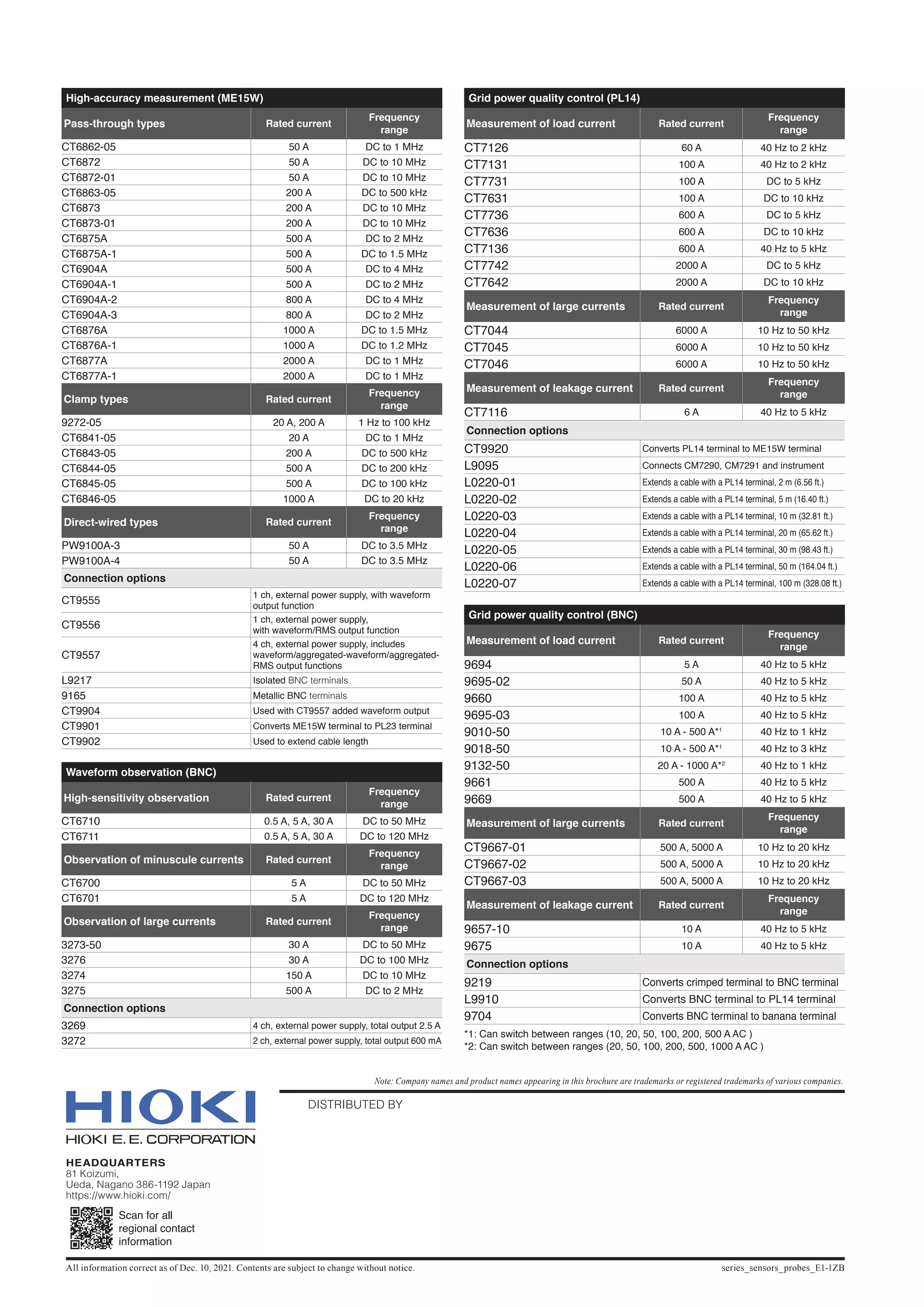

The document discusses Hioki's lineup of current sensors and current probes for various current measurement applications. It provides details on their specifications and suitability for different use cases, such as evaluating power devices, automotive systems, power quality maintenance, power consumption assessment, and more. The sensors and probes are optimized for measuring currents ranging from miniscule to large magnitudes, operating at frequencies from DC to the GHz range. Models are designed for high-accuracy measurement, waveform observation, and grid power quality control across industries including automotive, renewable energy, and electronics.