The document discusses a new method for detecting unintentional islanding in inverter-based distributed generation (DG) units, particularly using photovoltaic (PV) systems. It compares active and passive detection methods, highlighting the advantages of a hybrid approach that minimizes non-detection zones (NDZs) while maintaining power quality. Simulation results indicate that the proposed method effectively detects islanding conditions with improved performance under various operational modes.
![International Journal of Power Electronics and Drive System (IJPEDS)
Vol. 4, No. 4, December 2014, pp. 439~450
ISSN: 2088-8694 439
Journal homepage: http://iaesjournal.com/online/index.php/IJPEDS
Islanding Detection of Inverter Based DG Unit Using PV
System
M.Divyasree, L.Venkata Narasimha Rao
Department of Electrical and Electronics Engineering, K L University, A.P, India
Article Info ABSTRACT
Article history:
Received May 13, 2014
Revised Jun 31, 2014
Accepted Jul 20, 2014
Distributed generation (DG) units are rapidly increasing and most of them
are interconnected with distribution network to supply power into the
network as well as local loads Islanding operations of DG usually occur
when power supply from the main utility is interrupted due to several reasons
but the DG keeps supplying power into the distribution networks. a new
method for islanding detection of inverter-based distributed generation (DG).
Although active islanding detection techniques have smaller non detection
zones than passive techniques, active methods could degrade the system
power quality and are not as simple and easy to implement as passive
methods. The phenomenon of unintentional islanding occurs when a
distributed generator (DG) continues to feed power into the grid when power
flow from the central utility source has been interrupted. A simple islanding
detection scheme has been designed based on this idea. The proposed method
has been studied under multiple-DG operation modes and the UL 1741
islanding tests conditions and also using a PV system. The simulations
results, carried out by MATLAB/Simulink, show that the proposed method
has a small Non detection zone.
Keyword:
Distributed generation (DG)
Islanding
Non detection zone (NDZ)
Photovoltaic (PV)
Voltage-source inverter
Copyright © 2014 Institute of Advanced Engineering and Science.
All rights reserved.
Corresponding Author:
M.Divyasree,
Department of Electrical and Electronics Engineering,
K L University,
A.P, India.
Email: divyasree.madivada@gmail.com
1. INTRODUCTION
Distributed generation (DG) provides many potential benefits, such as Lower energy costs,
Improved reliability, improved power quality, Greater autonomy, upturn efficiency.In the last few years,
small DGs in the range of 100 kW have gained popularity amongst industry and utilities. Anti-islanding
detection methods can be divided into two main groups: passive and active methods. In passive methods, the
decision whether an islanding condition occurred or not is based on measuring a certain system parameter
and comparing it with a predetermined threshold. Active methods are designed to force the DG to be unstable
during an islanding situation. In general, islanding detection methods could be classified into three main
types that include active, passive, and communication-based methods. Passive methods, which are simple
and easy to implement, detect islanding by setting an upper and lower threshold on a system parameter.
Active methods, on the other hand, rely on injecting deliberate disturbances to the connected circuit
and then monitoring the response to determine an islanding condition [8]. Active methods include slide-mode
frequency shift (SMS) [9], active frequency drift (AFD) or frequency bias [10], and Sandia frequency shift
(SFS) [3]. Active methods have smaller NDZ, but, on the other hand, can degrade the power quality of the
power system [8]. Other active methods rely on deliberately injecting negative sequence current and
disturbance signals into the system through either the direct axis (d-axis) or the quadrature axis (q-axis)
current controllers [1], [3] to detect islanding. Communication-based methods have negligible NDZ, but are](https://image.slidesharecdn.com/0331may146257islandingedit-171213042142/75/Islanding-Detection-of-Inverter-Based-DG-Unit-Using-PV-System-1-2048.jpg)
![ ISSN: 2088-8694
IJPEDS Vol. 4, No. 4, December 2014 : 439 – 450
440
much more expensive than the former methods. A survey on the different islanding detection methods could
be found in [8] and [9]. Thus, passive islanding detection methods suffer from large Non detection zones
(NDZs). NDZs are defined as the loading conditions for which an islanding detection method would fail to
operate in a timely manner. To enhance the performance of passive methods, a hybrid passive method based
on monitoring the voltage unbalance and total harmonic distortion (THD) was proposed in [7].
This paper presents a new islanding detection method, which has the improvements of active and
passive islanding methods, minor NDZ, and excellent precision. The control strategy of the voltage-source
inverter has been designed to operate at unity power factor. Also, the dc side has been modelled by a
controllable dc voltage source. The main concept of this paper is to change the dc-link voltage considering
the PCC voltage changes during the islanding condition.
A simple and easy method like over/under voltage protection (OVP/UVP), can be used to detect an
islanding condition. Once the scale of voltage exceeds a determined starting point value, an islanding
condition is detected and DG is disconnected.
In this paper, the system is modelled in Section II. The proposed islanding detection method is
discussed in Section III. The performance of the proposed method is evaluated in Section IV. The last section
consists of conclusions.
2. SYSTEM UNDER STUDY
The system, which has been studied in this paper, is shown in Figure 1. This system consists of a
distribution network modelled by a three-phase voltage source behind impedance, a load modelled by a three-
phase constant impedance, and a DG system. The DG is modelled by a controllable dc voltage source behind
a three-phase inverter whose rating is 100 kW. The other parameters have been given in [3], [4], and [5].
Figure 1. Modelled system
Figure 2 shows the control scheme based on dq synchronous reference frame. In this scheme, the dc-
link voltage controller and reactive-power controller determine d and q components, respectively. The input
power extracted from the DG unit is fed into the dc link. Hence, the voltage controller counteracts the voltage
variation by specifying an adequate value of the d axis inverter current to balance the power flow of the dc
link [6]. The reactive power controller, shown in Figure 2, specifies the reference value for the q component
of the converter current. The reactive power reference value Qref is set to zero in order to model a unity power
factor DG operation. Also, Figure 2 shows two proportional-integral (PI) controllers for the d- and q-axis
current controls. The outputs of controllers obtain the reference voltages for the PWM signal generator. The
main features of the current control strategy are the limitation of the converter output current during a fault
condition, providing over current protection, and decreasing the fault current contribution of the unit [6]. The
instantaneous real and reactive power could be written in terms of the dq axis components, as follows [7],
[8]:
. (1)
Q = . (2)](https://image.slidesharecdn.com/0331may146257islandingedit-171213042142/75/Islanding-Detection-of-Inverter-Based-DG-Unit-Using-PV-System-2-2048.jpg)
![IJPEDS ISSN: 2088-8694
Islanding Detection of Inverter Based DG Unit Using PV System (M.Divyasree)
441
Where, Vdpcc is the phase peak value of the PCC voltage. idt and iqt are orthogonal components of
inverter currents. The dq components of the voltage and current are constant values in the steady-state
condition. Therefore, the controller provides the independent regulation d of q and components [7], [8]. The
instantaneous voltages of the three phases could be expressed by the following equation [7], [8]:
(3)
Where it(abc) represents the DG current three-phase components. Rf and Lf are the filter resistance and
inductance, respectively. Vt(abc) and Vpcc(abc) represent the DG terminal and PCC three phase voltages,
respectively.
Figure 2. Block diagram of the DG inverter controller.
By using Park’s transformation [7], (3) can be transformed to the rotating synchronous reference
frame, as follows [3], [7] and [8]:
(4)
Or,
0
0
(5)
Where,
= + (6)
= – (7)
The DG interface control is modified by using the set of equations shown in Figure 2. The
magnitude and angle of the modulating signal are calculated and then the switching pattern of the inverter has
been determined. PWM three-phase inverters should shape and control the three-phase output voltage in
magnitude and frequency with the essentially constant input dc voltage [9]. In the linear region (i.e., ma≤
1.0), the fundamental frequency component in the output voltage ((V_AN )1) determines the amplitude-
modulation ratio(ma) , by the following equation [9]:
(VAN1
) = ma
(8)](https://image.slidesharecdn.com/0331may146257islandingedit-171213042142/75/Islanding-Detection-of-Inverter-Based-DG-Unit-Using-PV-System-3-2048.jpg)
![ ISSN: 2088-8694
IJPEDS Vol. 4, No. 4, December 2014 : 439 – 450
442
ma
= (9)
Where Vcontrrol is the peak amplitude of the control signal and the Vtri is the amplitude of the triangular signal.
Therefore, the line-to-line rms voltage at the fundamental frequency can be written, as follows [9]:
V
L-L(line-line,rms)
=
√
√
(V
AN
) =
√
√
m
a
0.612m
a
(m
a
1.0 (10)
Now, the following equations can be written for Vdt and Vqt:
=0.612 m
a
cos ∅ (11)
=0.612 m
a
sin ∅ (12)
Where ∅ is the angle by which the inverter voltage vector leads the line voltage vector.
In a lossless inverter, the instantaneous power at the ac and dc terminals of the inverter is equal. This
power balance can be written, as follows:
= ) (13)
At the dc link, we have:
= (14)
By using (4) and (11)–(14), the following state equations can be written [7]:
= +
0
0
0 0
.
∅
.
sin ∅
.
cos ∅
.
sin ∅ 0
(15)
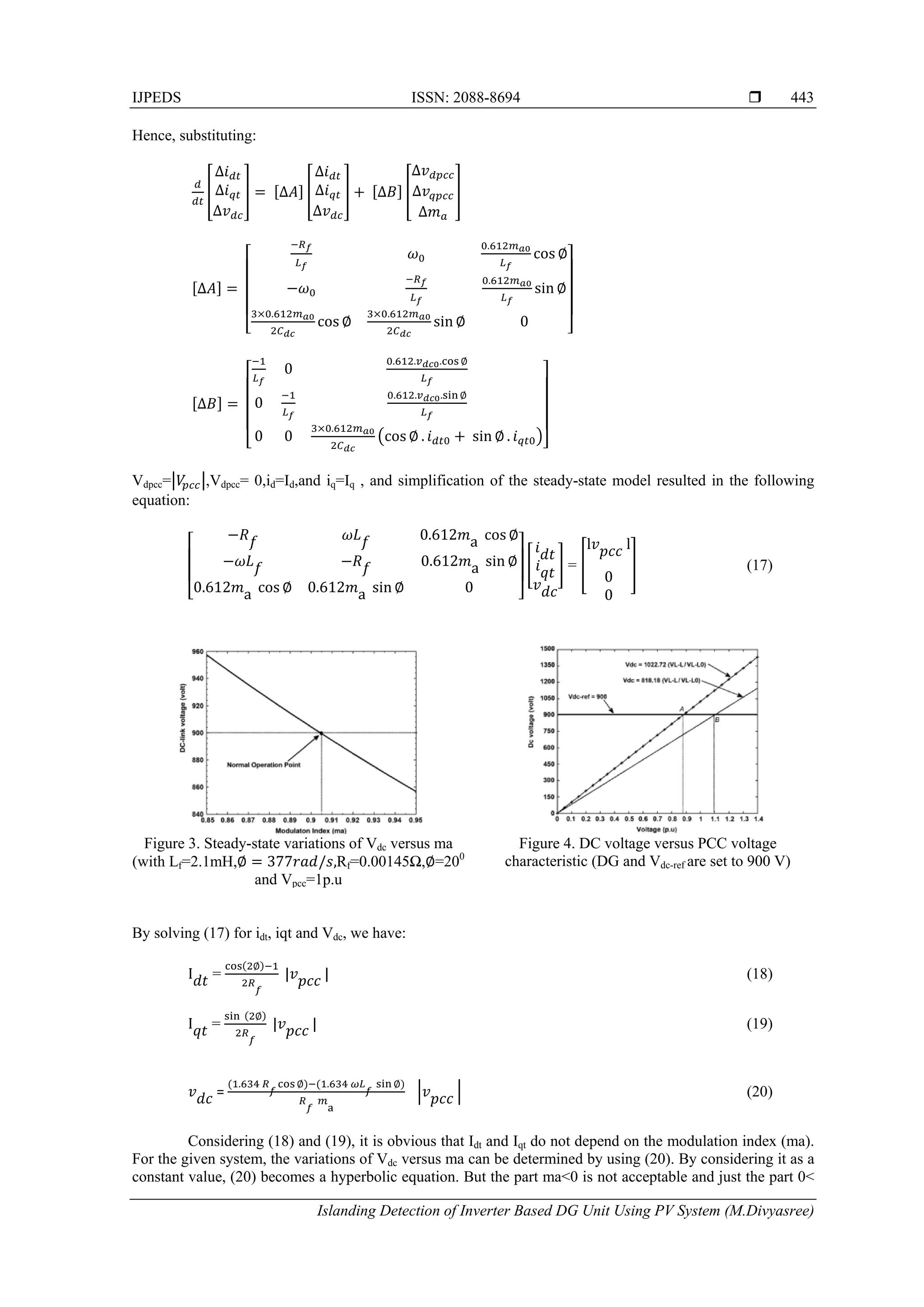
3. ISLANDING DETECTION METHOD
The acceptable voltage deviation is in the range of 88% to 110% of the nominal voltage [1], [2].
Any voltage deviation in this range should not be detected and the corresponding load condition would be
considered within the NDZ. It is assumed that DG has been designed to operate at a constant dc voltage of
900 V. In this section, a new analytical formulation is derived by the linearization of system state equations.
Then, a new Vdc -Vpcc characteristic of DG will be explained, and the performance of this method will be
evaluated.
3.1. Linearization of System State Equations
To measure the impact of deviation of ma on dc-link voltage,∅ has been kept constant and only ma
has been considered as a variable. As a result, (15) is a nonlinear equation. However, for a small perturbation
around the equilibrium point ma, the following linear set of equations can be obtained, where subscript 0
denotes steady-state values [7], as shown in (16) at the bottom of the page. The inverter steady-state model
can be obtained from the dynamic model by setting the derivative terms equal to zero. After transformation
from abc to the dq reference frame, the voltages and the currents become dc quantities.](https://image.slidesharecdn.com/0331may146257islandingedit-171213042142/75/Islanding-Detection-of-Inverter-Based-DG-Unit-Using-PV-System-4-2048.jpg)

![ ISSN: 2088-8694
IJPEDS Vol. 4, No. 4, December 2014 : 439 – 450
446
. . (32)
∆
∆
1 ∆ (33)
∆ ∆
∆
(34)
Table 1 shows the calculated NDZs for different values of k1 and k2. The selection of the Vdc - Vpcc
characteristic will have a great impact on NDZ. If the boundary between lower and upper limits of NDZ is a
large number, it will lead to a wide NDZ. In some cases, NDZ has a large gap (e.g., case No. 2), while for
other cases, it is relatively small (e.g., case No. 3). NDZ can either be represented in terms of power
mismatch or in terms of the load R, L, and C. An accurate presentation of the NDZ can be found in [5].
Table 1: Ndz Upper Andlowerlimits Fordifferent Vdc - Vpcc
Case
Number
Lower limit of NDZ Upper limit
of NDZ
1 450 450 825 1092.9
2 -450 1350 675 1478.6
3 810 90 885 938.5
The Details have been presented in the Appendix. This paper examines the NDZ of an OVP/UVP
and OFP/UVP islanding scheme in case of using the implemented Vdc - Vpcc characteristic for different
amounts of k1 and k2 . The results have been plotted in Figure 8.
Figure 8. NDZ of the Vdc -Vpcc characteristic for a different amount of k1and k2
4. MATLAB /SIMULINK RESULTS
Table 2. System, DG, and load parameters
Grid and Inverter Parameters
DG Output power 100kW
Switching Frequency 8000Hz
Input DC Voltage 900V
Voltage (Line to Line) 480V
Frequency 60Hz
Grid Resistance 0.02 Ω
Grid Inductance 0.3mH
Filter Inductance 2.1mH
DG Controller Parameters
Q Control 0.1, 0.01
Control 0.15, 9.78
PI Control 1, 1250
Load Parameters
R 2.304 Ω
L 0.00345 H
C 2037 µF](https://image.slidesharecdn.com/0331may146257islandingedit-171213042142/75/Islanding-Detection-of-Inverter-Based-DG-Unit-Using-PV-System-8-2048.jpg)
![IJPEDS ISSN: 2088-8694
Islanding Detection of Inverter Based DG Unit Using PV System (M.Divyasree)
447
In this section,the test system presented in Figure 1 which is simulated in MATLAB/Simulink. The
system, DG, and load parameters are listed in Table 2. The parameter Qref has been set to 0 MVAr. The
Islanding detection method has been tested for load with a quality factor (Qf) of 1.77. The proposed islanding
detection method has been also tested for various loading conditions specified in the UL 1741 Standard [3].
4.1. UL 1741 Testing
Based on the UL 1741 Standard, the active load power is adjusted to set the inverter at 25%, 50%,
100%,and 125% of the rated output power of the inverter. The reactive power has been adjusted between
95% and 105% of the balanced condition (unity power factor loading) in 1% steps [3]. The islanding
detection scheme is tested based on the procedure presented in [3]. The DG interface has been equipped with
the V_(dc-ref) characteristic given in (31) and islanding has occurred at t =0.8s.
The first simulation result using the proposed method is shown in Figure 9. This figure shows the
voltage at the PCC during an islanding condition, for the active load power adjusted at 50%, 100%, and
125% of its rated output power. The reactive power has been adjusted at 100% of the balanced condition. As
can be seen in Figure 9, the PCC voltage exceeds the OVP/UVP thresholds in less than 100ms (after the
occurrence of islanding).
Figire 9. PCC voltage using the proposed
characteristic for different loads
Figure 10. PCC voltagewith characteristic for
three cases
Figure 10 shows the voltage at the PCC during an islanding condition, for the following cases [4]:
Case 1) The load has been adjusted at 100% of rated active power with 101% reactive power in the
balanced condition.
Case 2) The load has been adjusted at 100% of the rated active power with 100% reactive power.
Case 3) The load has been adjusted at 100% of its rated active power with 99% reactive power.
Table 3. Load Parameters For UL 1741 TESTS
P% Q% R(Ω) L(H) C(µF)
50 100 4.603 0.00345 2037
125 100 1.841 0.00345 2037
100 99 2.304 0.003488 2037
100 100 2.304 0.00345 2037
100 101 2.304 0.003419 2037
4.2. Effect of Load Switching
The proposed islanding detection method has been tested for load switching in the grid-connected
operation mode. In parallel with the old load, which has been presented in Figure 1, the new load has been
switched at t= 0.5 s and disconnected at t= 1s. Three cases have been simulated in this test. In all cases, the
load apparent power is equal to 100 kVA but the power factor is 0.8 lead, 1.0 and 0.8 lag. The simulation
results that include the PCC voltage, and the DG active and reactive power outputs for three different loading
conditions have been presented in Figure 11. The voltage variation can be seen when the load is switched on
and off. For simulated cases, the voltage and frequency variations are within the standard values. It is obvious
that the proposed method does not interfere with the power system operation during normal conditions.
0.5 0.6 0.7 0.8 0.9 1.0 1.1 1.2 1.3 1.4 1.5
0
0.5
1
1.5
2
2.5
3
3.5
4
Time (sec)
PCCVoltage(p.u)
Pload = 50 kW
Pload = 100 kW
Pload = 125 kW
0 0.5 1 1.1 1.2 1.3 1.4 1.5
0
0.1
0.2
0.3
0.4
0.5
0.6
0.7
0.8
0.9
1
1.1
1.2
1.3
1.4
Time(sec)
PCCVoltage(p.u)
case 2
case 3
case 1](https://image.slidesharecdn.com/0331may146257islandingedit-171213042142/75/Islanding-Detection-of-Inverter-Based-DG-Unit-Using-PV-System-9-2048.jpg)


![ ISSN: 2088-8694
IJPEDS Vol. 4, No. 4, December 2014 : 439 – 450
450
REFERENCES
[1] IEEE Standard for Interconnecting Distributed Resources With Electric Power Systems, IEEE Std. 1547-2003.
2003.
[2] Static Inverter and Charge Controllers for Use in Photovoltaic Systems Standard UL. Northbrook, IL: Underwriters
Laboratories, Inc., 2001.
[3] HH Zeineldin. A droop curve for facilitating Islanding detection of inverter-based distributed generation. IEEE
Trans. Power Electron., vol. 24, no. 3, pp. 665–673, Mar. 2009.
[4] HH Zeineldin, JL Kirtley. A simple technique for Islanding detection with negligible non detection zone. IEEE Trans
Power Del., 2009; 24(2): 779–786.
[5] HH Zeineldin, EF EI-Saadany, MMA Salama. Impact of DG interface control on Islanding detection and non
detection zones. IEEE Trans. Power Del., 2006; 21(3): 1515–1523.
[6] F Katiraei, R Iravani, N Hatziargyriou, A Dimeas. Microgrids management. IEEE Power Energy Mag., 2008; 6(3):
54–65.
[7] C Schauder, H Mehta. Vector analysis and control of advanced static VAR compensators. Proc. Inst. Elect. Eng.,
1993; 15(3): 299–306.
[8] G Hernandez-Gonzalez, R Iravani. Current injection for active islanding detection of electronically-interfaced
distributed resources. IEEE Trans. Power Del., 2006; 21(3): 1698–1705.
[9] N Mohan. Power Electronics: Converters, Applications, and Design. New York: Wiley, 2002: 200–248.
[10] LAC Lopes, H Sun. Performance assessment of active frequency drifting Islanding detection methods. IEEE Trans.
Energy Convers., 2006; 21(1): 171–180.](https://image.slidesharecdn.com/0331may146257islandingedit-171213042142/75/Islanding-Detection-of-Inverter-Based-DG-Unit-Using-PV-System-12-2048.jpg)