Download to read offline
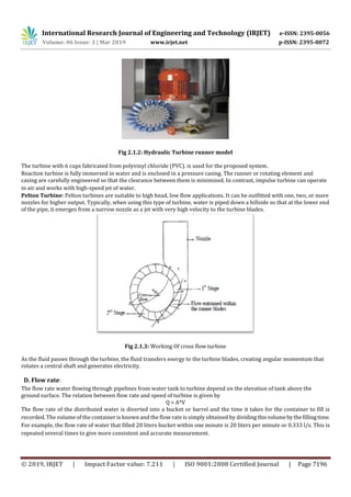
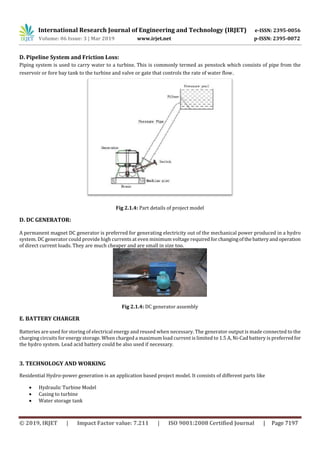
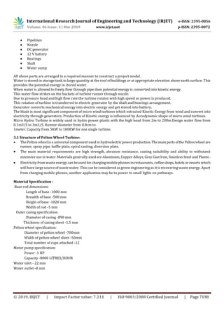

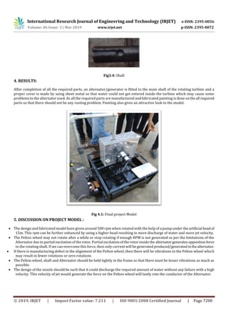

This document describes a proposed residential hydro power generation system to provide electricity for rural homes. It involves using the water pressure and flow from an elevated storage tank through household pipes to rotate a small-scale hydro turbine and generator. The system would include a turbine, generator, batteries for energy storage, and distribution of power to power lights, appliances, and other loads. The document provides details on estimating the available power based on head and flow rate, turbine design, generator and battery selection, and the overall working mechanism of using household water flow to generate useful electricity for homes.


