Download to read offline
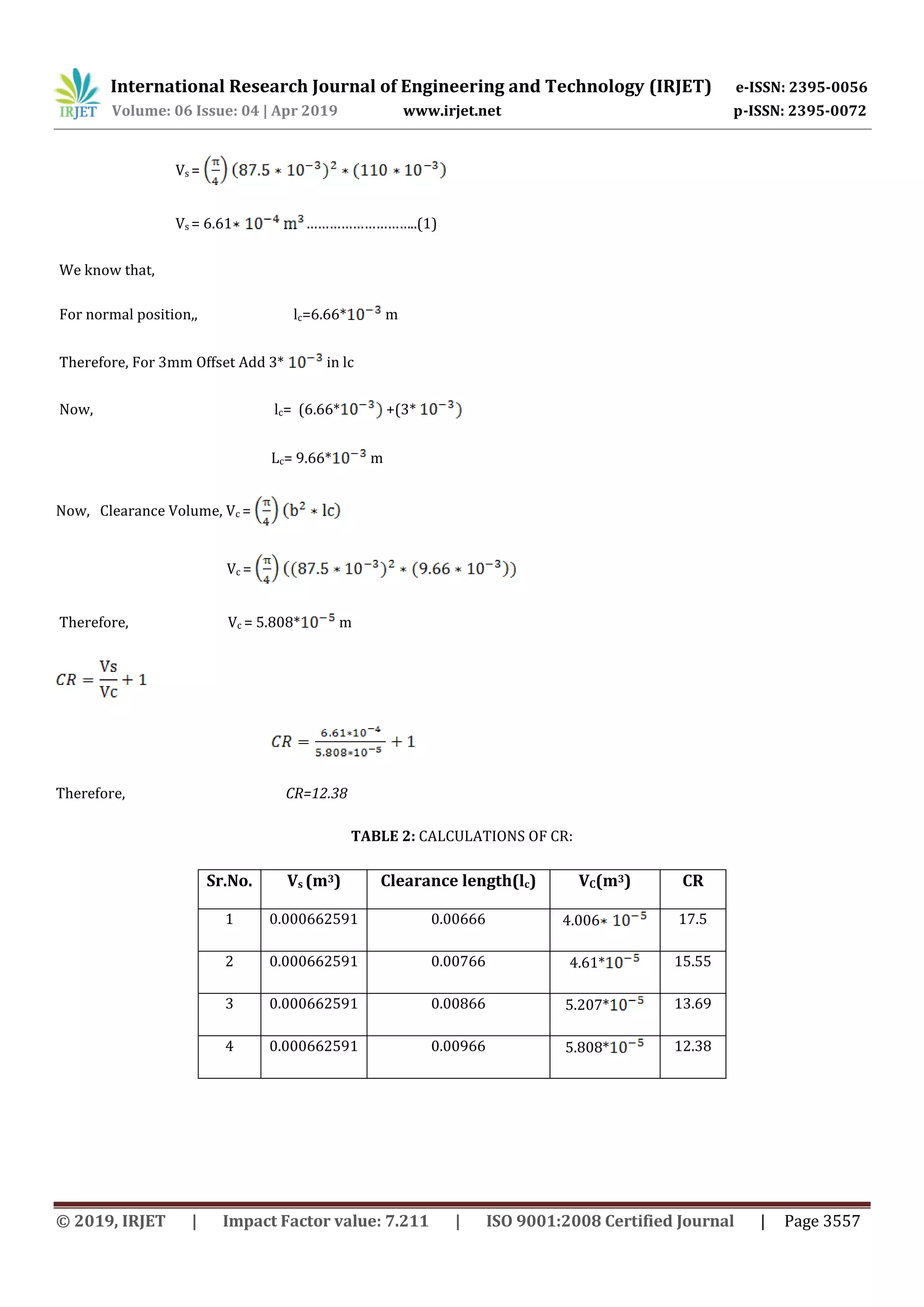

This document presents research on improving the performance of a single cylinder diesel engine by using a variable compression ratio. Experiments were conducted on the engine at compression ratios of 12.38, 13.69, 15.55, and 17.5 under different loads. The optimum compression ratio was found to be 13.69, which provided the best fuel efficiency and performance characteristics like brake power, brake thermal efficiency, and specific fuel consumption. Varying the compression ratio allows the engine to operate more efficiently at both low and high loads. The conclusions indicate that a compression ratio of 13.69 maximizes fuel efficiency and minimizes fuel consumption for the given engine.


