Download to read offline

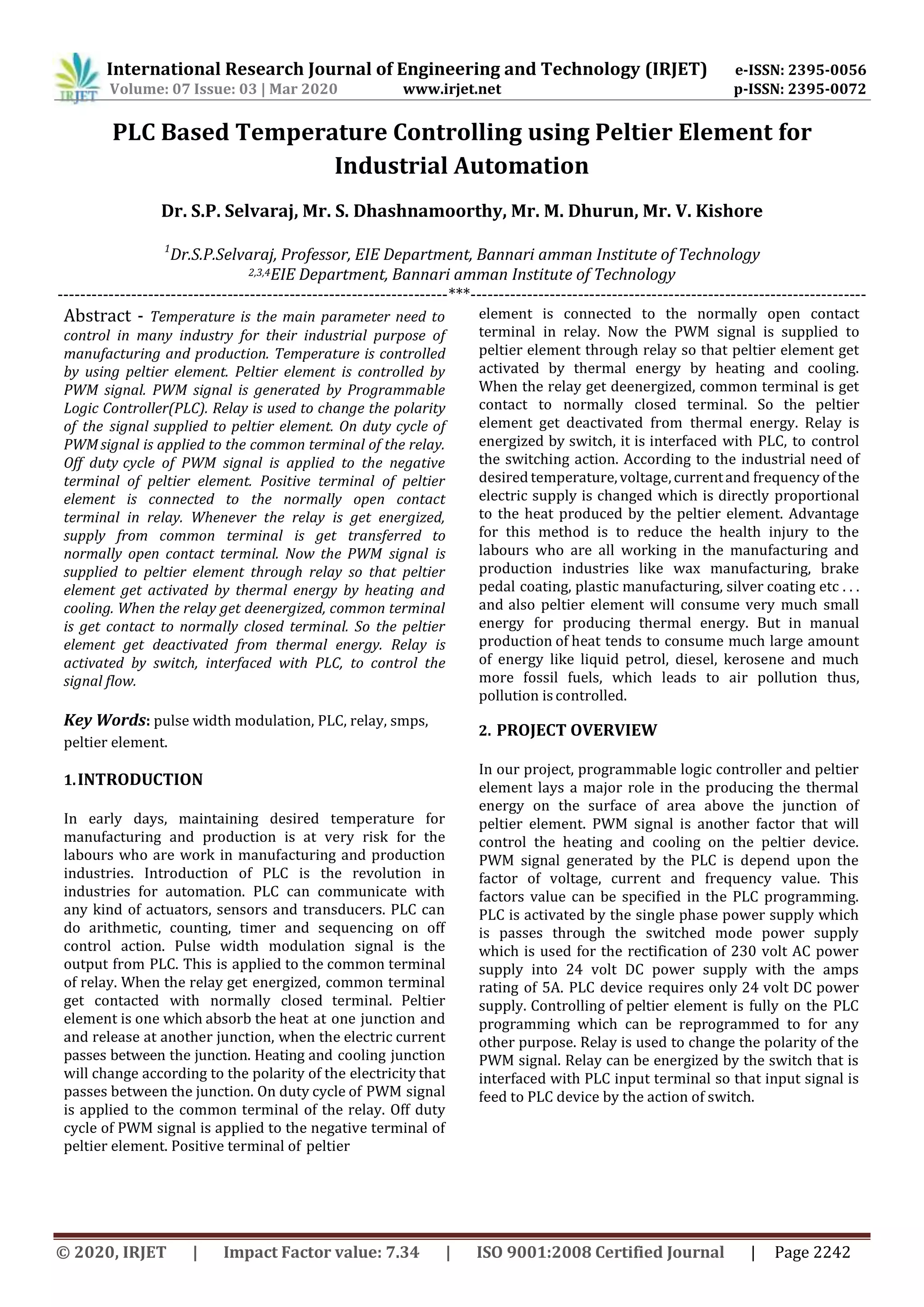
![International Research Journal of Engineering and Technology (IRJET) e-ISSN: 2395-0056
Volume: 07 Issue: 03 | Mar 2020 www.irjet.net p-ISSN: 2395-0072
© 2020, IRJET | Impact Factor value: 7.34 | ISO 9001:2008 Certified Journal | Page 2244
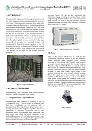
4.3. Peltier Element
Peltier element has two sides with the junction between
two sides for the flowing of electricity. Whenever there is
a flowing of electricity in the junction, heat is absorbed at
one side called cold junction, and released at another side
called heat junction. Rate of flow current in the junction
of peltier determine the rate of heating and cooling at the
sides of the peltier element. This is the basic principle
discovered by Jean Charles Athanase Peltier in the year of
1834. Following figure shows the picture if peltier
element following figure shows the peltier picture
Fig -4: Peltier Module
5.SOFTWARE DESCRIPTION
PLC programing can be done in the manufactures defined
software. After the introduction of processor based PLC,
high level computerized programming become more
popular for configuration of PLC to the desired extent.
Now the industrial automation is on the peak of the
country’s economy as well as individual’s personal
economy for the saving of unwanted expenditure, this
automation is done by the introduction of computerized
programming languages for different versions of PLC.
5.1 PLC Programming
Fig -5: Programming
6. RESULT AND CONCLUSION
Thus, the temperature is controlled by PLC using peltier
element. PWM signal plays a major role to control the
peltier element. Voltage, frequency and current value of
PWM signal determine the heating of peltier element.
Following figure shows the PWM signal.
When the input B0000 is set to be ON. Data from D0000
register is transferred to D0001 register. And the output
B0001 is set to be ON. Next, the data from the register
B0001 is transferred to the MW0402 register which
performs the frequency action for pulse width
modulation signal. Output
REFERENCES
Fig -6: Pwm Signal
is generated . The followingfigureshowstheprogramming
of PLC to configure the controller to generate the pulse
width modulation signal.
[1] J. C. Peltier. Nouvelles Experiences sur la Caloricite
des Courants Electriques. Ann. Chim. Phys. 1834, 56,
pp 371–386.
[2] E. H. Lentz. Electrical Experiment of Academician
Lentz. Water Freezing by Galvanic Stream. Bibliotec.
Chten. 1838, 28, pp 44–48.
[3] Jonathan Schoenfeld, Integration of a
Thermoelectric Subcooler Into a Carbon Dioxide
Transcritical Vapor Compression Cycle Refrigeration
System, International Refrigeration and Air
ConditioningConference,2008.](https://image.slidesharecdn.com/irjet-v7i3445-201217095437/85/IRJET-PLC-based-Temperature-Controlling-using-Peltier-Element-for-Industrial-Automation-3-320.jpg)
![International Research Journal of Engineering and Technology (IRJET) e-ISSN: 2395-0056
Volume: 07 Issue: 03 | Mar 2020 www.irjet.net p-ISSN: 2395-0072
© 2020, IRJET | Impact Factor value: 7.34 | ISO 9001:2008 Certified Journal | Page 2245
[4] Michael Ralf Starke, Thermoelectrics for Cooling
Power Electronics, The University of Tennessee,
Knoxville,2006.
[5] Y.Y. Hsiao, W.C. Chang, S.L. Chen, “A mathematic
model of thermoelectric module with applications
on waste heat recovery from automobile engine” in
Elsevier Journal of Energy volume 35 (2010) pages
447–1454.
[6] AdithyaVenugopal, Karan Narang et al, “Cost-
effective Refrigerator Using Thermoelectric Effect
and Phase Change Materials”, International Journal
of Scientific & Engineering Research, Volume 5,
Issue 2, February- 2014.
[7] Nash, J. D., and J. N. Moum, 1999: Estimating
salinity variance dissipation rate from conductivity
microstructure measurements. J. Atmos. Oceanic
Technol., 16, 263–274.
[8] Oakey, N. S., 1982: Determination of the rate of
dissipation of turbulent energy from simultaneous
temperature and velocity shear microstructure
measurements. J. Phys. Oceanogr., 12, 256–271.
[9] Omega Engineering, 1995: The Temperature
Handbook. Omega Engineering. [Available online
at www.omega.com.] 10. Osborn, 1T.](https://image.slidesharecdn.com/irjet-v7i3445-201217095437/85/IRJET-PLC-based-Temperature-Controlling-using-Peltier-Element-for-Industrial-Automation-4-320.jpg)

1) The document describes a system for controlling temperature in industries using a PLC, relay, and peltier element. 2) A PLC generates a PWM signal to control the peltier element. A relay is used to change the polarity of the signal to the peltier element to activate heating and cooling. 3) The system allows automatic temperature control for industrial processes like manufacturing, reducing health risks to workers from manual temperature control methods.