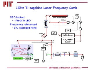
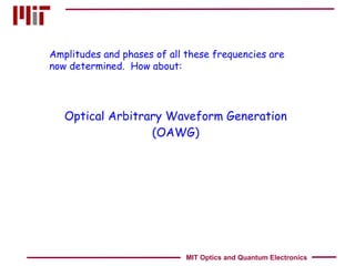
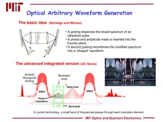
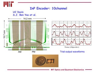
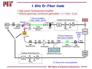
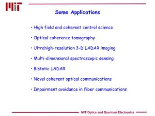
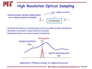
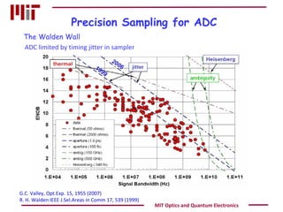
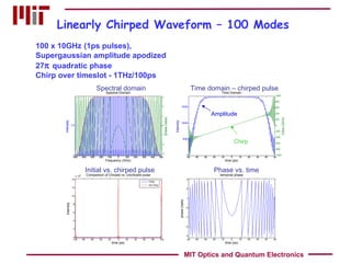
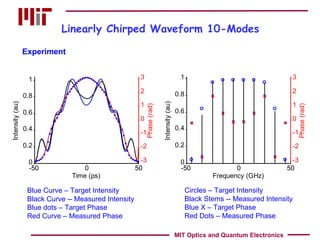
Clocks, Combs and OAWG Erich P. Ippen Massachusetts Institute of Technology Cambridge, MA 02139 [email_address] NEOSA September 15, 2011 MIT Optics and Quantum Electronics
Outline Femtosecond lasers – few cycle pulses Carrier envelope phase control  Optical frequency combs Arbitrary optical waveforms Applications Clocks Precision sampling and timing MIT Optics and Quantum Electronics
The 5-fs Ti:sapphire Laser Kerr lens modelocking (KLM) Double-chirped mirrors All-solid state, prismless cavity 5 fs = less than 2 cycles Octave-spanning spectrum MIT Optics and Quantum Electronics
Under Each Pulse is a Short Waveform The electric field waveform slips under the envelope from pulse to pulse – if group delay and phase delay differ. Carrier-envelope phase slip  2n G L/c MIT Optics and Quantum Electronics BBO 570 nm filter PBS RF spectrum analyzer PMT Second harmonic generation
Control Over the Optical Phase  Carrier-envelope phase stabilization An optical clockwork ! The optical frequency is an exact multiple of the pulse rep-rate. MIT Optics and Quantum Electronics
A Clock an oscillator a clockwork Pendulum - Christiaan Huygens 1656  Chronometer - John Harrison (H4) 1761 (10 -6  ~ 1 sec/ 9 days ) Quartz - W. Marrison, Bell Labs, 1928 (10 -8  ~ 1 sec/3yrs   ) Cesium atom - 1955 (10 -10  ~ 1sec/300yrs) Hg ion – 5x10 -18  ~ 10sec since big bang Atomic fountain - NIST-F1 (1.7x10 -15  ~ 1sec/20Myrs) and MIT Optics and Quantum Electronics
Clockwork by Frequency Multiplication From the 9.192 GHz Cs frequency standard to the 456 THz (657nm) Ca transition 1999 10 -14  accuracy 10 lasers 8 phase-lock loops MIT Optics and Quantum Electronics
The Clockwork in the Frequency Domain 1f-to-2f frequency locking Octave-spanning frequency comb This locks the rep rate to the optical frequency.  Still need an optical reference. MIT Optics and Quantum Electronics laser modes exact multiples of f rep 2 nd  harmonics
Locking to the 3.39  m HeNe Reference via DFG He-Ne/CH 4 Laser 3.39  m Transportable Stability ~ 10 -14 Difference frequency generation in PPLN DFG MIT Optics and Quantum Electronics
A Portable Optical Frequency Reference Monolithic “ sitall / zerodur” resonator  Compact Ultrastable (< 10 -14 ) Transportable Phase- locked He-Ne laser 3.39   m output Mikhail Gubin, Lebedev Institute Methane-stabilized He-Ne Laser:    = 3.39  m MIT Optics and Quantum Electronics
L 1GHz Ti:sapphire Laser Frequency Comb MIT Optics and Quantum Electronics CEO locked Frequency referenced 1f-to-2f in LBO CH 4 - stabilized HeNe
Optical Arbitrary Waveform Generation (OAWG) Amplitudes and phases of all these frequencies are now determined.  How about: MIT Optics and Quantum Electronics
Completely Arbitrary Waveforms Fast modulator array Spectrum locked to “absolute” grid Arbitrary electrical field waveform ! Pulse-to-pulse AM & PM Arbitrary spectrum MIT Optics and Quantum Electronics f t
Optical Arbitrary Waveform Generation The basic idea  (Heritage and Weiner) A grating disperses the broad spectrum of an ultrashort pulse. A phase and amplitude mask is inserted into the Fourier plane. A second grating recombines the modified spectrum into a “shaped” waveform.  The advanced integrated version  (UC Davis)   In current technology, a small band of frequencies passes through each modulator element. Modulator array Arrayed Waveguide Grating MIT Optics and Quantum Electronics
InP Encoder: 10channel 14.2 mm UC Davis S.J. Ben Yoo et al. Trial output waveforms 10.7 mm PM AM MIT Optics and Quantum Electronics
Packaged InP OAWG (10 Ch AM+ 10 Ch PM) x 10 GHz InPhi & UC Davis MIT Optics and Quantum Electronics
Route to 10 GHz Precise dispersion compensation  Gain flattening Optimized output mirror Tight focusing; low loss 1.5cm DCM11G 1% Inverse Gain OC DCM11G 1.5cm  DCM11G 2.28mm Ti:Sa 5.5 GHz 1.5cm DCM11G 1% Inverse Gain OC DCM11G 1.5cm  DCM11G 2.28mm Ti:Sa 3.3 GHz 10 GHz 0.75cm DCM11G 1% Inverse Gain OC DCM11G 0.75cm  DCM11G 2.28mm Ti:Sa MIT Optics and Quantum Electronics
Alternate Route:  10 x Rep-Rate Multiplication by Filtering Mode Matching Optics Balanced Detector Brewster Plate PBS λ /4 4% BS Loop Filter Piezo Driver Output 10xf  Piezo ML Laser Laser Rep Rate: f Super-invar Hänsch-Couillaud locking method F = 156 => 30dB sidemode suppression F = 2100 => 55 dB sidemode suppression J. Chen et al. Opt.Lett.32, 1556, 2007 10x  F = 2100 MIT Optics and Quantum Electronics
Rep Rate Multiplication with Monolithically Integrated Interleavers M. Sander et al,  CLEO 2011: CThY5 Thermal tuning for optimizing delays coupling coefficients Side-mode suppression limited by offsets in coupling coefficients waveguide dispersion
GHz Er:Fiber Laser Technology MIT Optics and Quantum Electronics
Wider Goal: Two Octaves of Frequency Comb Ti:sapphire Er/Yb glass/fiber 0.5   m 1.0   m 1.5   m 2.0   m 3.39   m /2 f-to-2f + DFG f-to-2f +   DFG More power per comb line Facilitates demultiplexing via AWG HeNe-CH 4 3.39  m reference for DFG MIT Optics and Quantum Electronics
1-GHz Er-doped Fiber Laser P output  = 27.4 mW W intracav  = 283 pJ P pump  = 380 mW 187 fs pulses 17.5 nm BW MIT Optics and Quantum Electronics SBR Partial Reflector OC 10% Output Erbium Fiber  (92mm) FC/PC connector WDM 977 nm SMF28e (11mm)
Integrated Femtosecond Waveguide Laser Integrated gain + dispersion compensation Integrated pump coupling Integrated loop mirror/output coupler Butt-coupled SBR 44x18 mm 2 400 MHz rep rate 440 fs pulse duraton MIT Optics and Quantum Electronics
High power femtosecond amplifier Octave-spanning  continuum generation:    = 1  m - 2   m  1.55   m oscillator 1 GHz, 200fs, 20mW Output 100fs 2 W Positive dispersion high power amplifier 1 GHz Er-Fiber Comb D. Chao et al, to be published MIT Optics and Quantum Electronics PC SMF Pre-chirp Fiber HNLF ISO Pre-Amplifier PC ISO WDM 10W Raman Fiber Laser Liekki Er-doped Fiber SMF Post-chirp  1480nm PUMP Lens 980 nm Liekki Er-doped Fiber (83 mm) PUMP ISO 980 nm Collimator Dichroic Lens Lens SBR OC (5%) PZT AOM Lens Loop Filter ~ PD Amp BPF LO Feedback Control Electronics DFG HeNe SHG (f-2f) Loop Filter ~ PD Amp BPF LO Feedback Control Electronics
1 GHz Octave-Spanning 1µm-2µm Continuum  1012nm 7.09mW 2024nm 65.37mW 1 GHz Source 1 GHz Supercontinuum 1082nm 8.56mW 1590nm 47.02mW 1f-2f DFG MIT Optics and Quantum Electronics
Some Applications High field and coherent control science Optical coherence tomography Ultrahigh-resolution 3-D LADAR imaging Multi-dimensional spectroscopic sensing Bistatic LADAR Novel coherent optical communications Impairment avoidance in fiber communications MIT Optics and Quantum Electronics
High Resolution Optical Sampling Application: Photonic analog –to- digital conversion Amplitude fluctuations of sampling pulse can be cancelled by balanced detection Resolution and dynamic range limited by timing jitter Modelocked lasers can achieve quantum-limited jitter Optical pulses sample analog signal on an electro-optical modulator voltage waveform MIT Optics and Quantum Electronics optical sampling pulse I(t) voltage waveform V(t) timing jitter V(t) E-O Modulator
Precision Sampling for ADC G.C. Valley, Opt.Exp. 15, 1955 (2007) R. H. Walden IEEE J.Sel.Areas in Comm 17, 539 (1999) ADC limited by timing jitter in sampler The Walden Wall MIT Optics and Quantum Electronics
40 Gs/s 8-bit Optical Bit Interleaved ADC 4mm x 4mm chip 20 HIC ring filters with 8   m radius, 20 nm  FSR SiGe detectors with  2 GHz BW, 100 nW NEP Analog Si modulator  bandwidth 50 GHz  Ultra Low-jitter direct  optical sampling Kaertner, Ippen,  Hoyt, Smith, Ram, MIT Lincoln Lab MIT Optics and Quantum Electronics
Synchronization of a Large Scale X-Ray FEL Kim et al., MIT/DESY MIT Optics and Quantum Electronics
Acknowledgments Andrew Benedick Hyunil Byun Jeff Chen David Chao Jonathan Morse Michelle Sander Jason Sickler Franz Kärtner Noah Chang Jung-Won Kim MIT Optics and Quantum Electronics
Linearly Chirped Waveform – 10 Modes 10 x 10GHz (10ps pulses) Supergaussian amplitude apodized 2    quadratic phase Chirp over timeslot - 100GHz/100ps Spectral domain Time domain – chirped pulse Phase vs. time Chirp Amplitude  Initial vs. chirped pulse Theory MIT Optics and Quantum Electronics
Linearly Chirped Waveform – 100 Modes  100 x 10GHz   (1ps pulses),  Supergaussian amplitude apodized 27    quadratic phase Chirp over timeslot - 1THz/100ps Spectral domain Time domain – chirped pulse Phase vs. time Chirp Amplitude  Initial vs. chirped pulse MIT Optics and Quantum Electronics
Linearly Chirped Waveform 10-Modes Blue Curve – Target Intensity  Black Curve -- Measured Intensity Blue dots – Target Phase Red Curve – Measured Phase Circles – Target Intensity  Black Stems -- Measured Intensity Blue X – Target Phase Red Dots – Measured Phase Experiment MIT Optics and Quantum Electronics

Ippen nes osa 9-15-11

  • 1.
    Clocks, Combs andOAWG Erich P. Ippen Massachusetts Institute of Technology Cambridge, MA 02139 [email_address] NEOSA September 15, 2011 MIT Optics and Quantum Electronics
  • 2.
    Outline Femtosecond lasers– few cycle pulses Carrier envelope phase control Optical frequency combs Arbitrary optical waveforms Applications Clocks Precision sampling and timing MIT Optics and Quantum Electronics
  • 3.
    The 5-fs Ti:sapphireLaser Kerr lens modelocking (KLM) Double-chirped mirrors All-solid state, prismless cavity 5 fs = less than 2 cycles Octave-spanning spectrum MIT Optics and Quantum Electronics
  • 4.
    Under Each Pulseis a Short Waveform The electric field waveform slips under the envelope from pulse to pulse – if group delay and phase delay differ. Carrier-envelope phase slip  2n G L/c MIT Optics and Quantum Electronics BBO 570 nm filter PBS RF spectrum analyzer PMT Second harmonic generation
  • 5.
    Control Over theOptical Phase Carrier-envelope phase stabilization An optical clockwork ! The optical frequency is an exact multiple of the pulse rep-rate. MIT Optics and Quantum Electronics
  • 6.
    A Clock anoscillator a clockwork Pendulum - Christiaan Huygens 1656 Chronometer - John Harrison (H4) 1761 (10 -6 ~ 1 sec/ 9 days ) Quartz - W. Marrison, Bell Labs, 1928 (10 -8 ~ 1 sec/3yrs ) Cesium atom - 1955 (10 -10 ~ 1sec/300yrs) Hg ion – 5x10 -18 ~ 10sec since big bang Atomic fountain - NIST-F1 (1.7x10 -15 ~ 1sec/20Myrs) and MIT Optics and Quantum Electronics
  • 7.
    Clockwork by FrequencyMultiplication From the 9.192 GHz Cs frequency standard to the 456 THz (657nm) Ca transition 1999 10 -14 accuracy 10 lasers 8 phase-lock loops MIT Optics and Quantum Electronics
  • 8.
    The Clockwork inthe Frequency Domain 1f-to-2f frequency locking Octave-spanning frequency comb This locks the rep rate to the optical frequency. Still need an optical reference. MIT Optics and Quantum Electronics laser modes exact multiples of f rep 2 nd harmonics
  • 9.
    Locking to the3.39  m HeNe Reference via DFG He-Ne/CH 4 Laser 3.39  m Transportable Stability ~ 10 -14 Difference frequency generation in PPLN DFG MIT Optics and Quantum Electronics
  • 10.
    A Portable OpticalFrequency Reference Monolithic “ sitall / zerodur” resonator Compact Ultrastable (< 10 -14 ) Transportable Phase- locked He-Ne laser 3.39  m output Mikhail Gubin, Lebedev Institute Methane-stabilized He-Ne Laser:  = 3.39  m MIT Optics and Quantum Electronics
  • 11.
    L 1GHz Ti:sapphireLaser Frequency Comb MIT Optics and Quantum Electronics CEO locked Frequency referenced 1f-to-2f in LBO CH 4 - stabilized HeNe
  • 12.
    Optical Arbitrary WaveformGeneration (OAWG) Amplitudes and phases of all these frequencies are now determined. How about: MIT Optics and Quantum Electronics
  • 13.
    Completely Arbitrary WaveformsFast modulator array Spectrum locked to “absolute” grid Arbitrary electrical field waveform ! Pulse-to-pulse AM & PM Arbitrary spectrum MIT Optics and Quantum Electronics f t
  • 14.
    Optical Arbitrary WaveformGeneration The basic idea (Heritage and Weiner) A grating disperses the broad spectrum of an ultrashort pulse. A phase and amplitude mask is inserted into the Fourier plane. A second grating recombines the modified spectrum into a “shaped” waveform. The advanced integrated version (UC Davis) In current technology, a small band of frequencies passes through each modulator element. Modulator array Arrayed Waveguide Grating MIT Optics and Quantum Electronics
  • 15.
    InP Encoder: 10channel14.2 mm UC Davis S.J. Ben Yoo et al. Trial output waveforms 10.7 mm PM AM MIT Optics and Quantum Electronics
  • 16.
    Packaged InP OAWG(10 Ch AM+ 10 Ch PM) x 10 GHz InPhi & UC Davis MIT Optics and Quantum Electronics
  • 17.
    Route to 10GHz Precise dispersion compensation Gain flattening Optimized output mirror Tight focusing; low loss 1.5cm DCM11G 1% Inverse Gain OC DCM11G 1.5cm DCM11G 2.28mm Ti:Sa 5.5 GHz 1.5cm DCM11G 1% Inverse Gain OC DCM11G 1.5cm DCM11G 2.28mm Ti:Sa 3.3 GHz 10 GHz 0.75cm DCM11G 1% Inverse Gain OC DCM11G 0.75cm DCM11G 2.28mm Ti:Sa MIT Optics and Quantum Electronics
  • 18.
    Alternate Route: 10 x Rep-Rate Multiplication by Filtering Mode Matching Optics Balanced Detector Brewster Plate PBS λ /4 4% BS Loop Filter Piezo Driver Output 10xf Piezo ML Laser Laser Rep Rate: f Super-invar Hänsch-Couillaud locking method F = 156 => 30dB sidemode suppression F = 2100 => 55 dB sidemode suppression J. Chen et al. Opt.Lett.32, 1556, 2007 10x F = 2100 MIT Optics and Quantum Electronics
  • 19.
    Rep Rate Multiplicationwith Monolithically Integrated Interleavers M. Sander et al, CLEO 2011: CThY5 Thermal tuning for optimizing delays coupling coefficients Side-mode suppression limited by offsets in coupling coefficients waveguide dispersion
  • 20.
    GHz Er:Fiber LaserTechnology MIT Optics and Quantum Electronics
  • 21.
    Wider Goal: TwoOctaves of Frequency Comb Ti:sapphire Er/Yb glass/fiber 0.5  m 1.0  m 1.5  m 2.0  m 3.39  m /2 f-to-2f + DFG f-to-2f + DFG More power per comb line Facilitates demultiplexing via AWG HeNe-CH 4 3.39  m reference for DFG MIT Optics and Quantum Electronics
  • 22.
    1-GHz Er-doped FiberLaser P output = 27.4 mW W intracav = 283 pJ P pump = 380 mW 187 fs pulses 17.5 nm BW MIT Optics and Quantum Electronics SBR Partial Reflector OC 10% Output Erbium Fiber (92mm) FC/PC connector WDM 977 nm SMF28e (11mm)
  • 23.
    Integrated Femtosecond WaveguideLaser Integrated gain + dispersion compensation Integrated pump coupling Integrated loop mirror/output coupler Butt-coupled SBR 44x18 mm 2 400 MHz rep rate 440 fs pulse duraton MIT Optics and Quantum Electronics
  • 24.
    High power femtosecondamplifier Octave-spanning continuum generation:  = 1  m - 2  m 1.55  m oscillator 1 GHz, 200fs, 20mW Output 100fs 2 W Positive dispersion high power amplifier 1 GHz Er-Fiber Comb D. Chao et al, to be published MIT Optics and Quantum Electronics PC SMF Pre-chirp Fiber HNLF ISO Pre-Amplifier PC ISO WDM 10W Raman Fiber Laser Liekki Er-doped Fiber SMF Post-chirp 1480nm PUMP Lens 980 nm Liekki Er-doped Fiber (83 mm) PUMP ISO 980 nm Collimator Dichroic Lens Lens SBR OC (5%) PZT AOM Lens Loop Filter ~ PD Amp BPF LO Feedback Control Electronics DFG HeNe SHG (f-2f) Loop Filter ~ PD Amp BPF LO Feedback Control Electronics
  • 25.
    1 GHz Octave-Spanning1µm-2µm Continuum 1012nm 7.09mW 2024nm 65.37mW 1 GHz Source 1 GHz Supercontinuum 1082nm 8.56mW 1590nm 47.02mW 1f-2f DFG MIT Optics and Quantum Electronics
  • 26.
    Some Applications Highfield and coherent control science Optical coherence tomography Ultrahigh-resolution 3-D LADAR imaging Multi-dimensional spectroscopic sensing Bistatic LADAR Novel coherent optical communications Impairment avoidance in fiber communications MIT Optics and Quantum Electronics
  • 27.
    High Resolution OpticalSampling Application: Photonic analog –to- digital conversion Amplitude fluctuations of sampling pulse can be cancelled by balanced detection Resolution and dynamic range limited by timing jitter Modelocked lasers can achieve quantum-limited jitter Optical pulses sample analog signal on an electro-optical modulator voltage waveform MIT Optics and Quantum Electronics optical sampling pulse I(t) voltage waveform V(t) timing jitter V(t) E-O Modulator
  • 28.
    Precision Sampling forADC G.C. Valley, Opt.Exp. 15, 1955 (2007) R. H. Walden IEEE J.Sel.Areas in Comm 17, 539 (1999) ADC limited by timing jitter in sampler The Walden Wall MIT Optics and Quantum Electronics
  • 29.
    40 Gs/s 8-bitOptical Bit Interleaved ADC 4mm x 4mm chip 20 HIC ring filters with 8  m radius, 20 nm FSR SiGe detectors with 2 GHz BW, 100 nW NEP Analog Si modulator bandwidth 50 GHz Ultra Low-jitter direct optical sampling Kaertner, Ippen, Hoyt, Smith, Ram, MIT Lincoln Lab MIT Optics and Quantum Electronics
  • 30.
    Synchronization of aLarge Scale X-Ray FEL Kim et al., MIT/DESY MIT Optics and Quantum Electronics
  • 31.
    Acknowledgments Andrew BenedickHyunil Byun Jeff Chen David Chao Jonathan Morse Michelle Sander Jason Sickler Franz Kärtner Noah Chang Jung-Won Kim MIT Optics and Quantum Electronics
  • 32.
    Linearly Chirped Waveform– 10 Modes 10 x 10GHz (10ps pulses) Supergaussian amplitude apodized 2  quadratic phase Chirp over timeslot - 100GHz/100ps Spectral domain Time domain – chirped pulse Phase vs. time Chirp Amplitude Initial vs. chirped pulse Theory MIT Optics and Quantum Electronics
  • 33.
    Linearly Chirped Waveform– 100 Modes 100 x 10GHz (1ps pulses), Supergaussian amplitude apodized 27  quadratic phase Chirp over timeslot - 1THz/100ps Spectral domain Time domain – chirped pulse Phase vs. time Chirp Amplitude Initial vs. chirped pulse MIT Optics and Quantum Electronics
  • 34.
    Linearly Chirped Waveform10-Modes Blue Curve – Target Intensity Black Curve -- Measured Intensity Blue dots – Target Phase Red Curve – Measured Phase Circles – Target Intensity Black Stems -- Measured Intensity Blue X – Target Phase Red Dots – Measured Phase Experiment MIT Optics and Quantum Electronics

Editor's Notes

  • #7 Cs clock is now the standard for the second (since 1968?). Optical clocks (Hg+ (Bergquist), Yb+, Sr+ ions) surpassed Cs in 2006 – but can still only be considered secondary standards. “ Time too good to be true.” Accuracies so good that altitude differences of a few feet due to gravitational effects can be observed.
  • #12 HeNe amplifier-laser offset from oscillator by 70MHz. Comparison then removes noise of 70MHz oscillator. Ti:saph jitter = 25fs 1kHz-10MHz. Allen variance: stability currently limited to about 10^ -12 due to problem with HeNe laser. The spectrum enhancing output coupler will enhance the DFG beat signal by ~4dB (currently 30dB). The new output coupler will also give the power increases necessary to allow f-2f self referencing (current 55dB).
  • #27 Sub-diffraction – synthetic aperture;1-mm 3-D resolution at 20km, 100um resolution at 1.5km Sensing – recognize multiple compounds at same time
  • #31 Kim – sub-10fs jitter (&lt; 1MHz – 300m roundtrip limited) and drift (days)