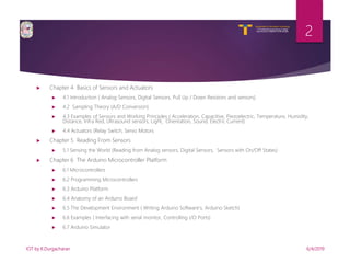
SlideShare a Scribd company logo
V R Siddhartha Engineering College
Autonomous and Affiliated to JNTUK,
Kakinada
Department of Information Technology
INTERNET OF
THINGS
UNIT-2
-BY
K.DURGACHARAN
V R Siddhartha Engineering College
Autonomous and Affiliated to JNTUK, Kakinada
Department of Information Technology
 Chapter 4 Basics of Sensors and Actuators
 4.1 Introduction ( Analog Sensors, Digital Sensors, Pull Up / Down Resistors and sensors)
 4.2 Sampling Theory (A/D Conversion)
 4.3 Examples of Sensors and Working Principles ( Acceleration, Capacitive, Piezoelectric, Temperature, Humidity,
Distance, Infra Red, Ultrasound sensors, Light, Orientation, Sound, Electric Current)
 4.4 Actuators (Relay Switch, Servo Motors
 Chapter 5 Reading From Sensors
 5.1 Sensing the World (Reading from Analog sensors, Digital Sensors, Sensors with On/Off States)
 Chapter 6 The Arduino Microcontroller Platform
 6.1 Microcontrollers
 6.2 Programming Microcontrollers
 6.3 Arduino Platform
 6.4 Anatomy of an Arduino Board
 6.5 The Development Environment ( Writing Arduino Software's, Arduino Sketch)
 6.6 Examples ( Interfacing with serial monitor, Controlling I/O Ports)
 6.7 Arduino Simulator
6/4/2019IOT by K.Durgacharan
2
V R Siddhartha Engineering College
Autonomous and Affiliated to JNTUK, Kakinada
Department of Information Technology
Chapter 4
(Basics of Sensors and Actuators)
 Basics of Sensors and Actuators
 4.1 Introduction (Analog Sensors, Digital Sensors, Pull Up / Down
Resistors and sensors)
 4.2 Sampling Theory (A/D Conversion)
 4.3 Examples of Sensors and Working Principles (Acceleration,
Capacitive, Piezoelectric, Temperature, Humidity, Distance, Infra Red,
Ultrasound sensors, Light, Orientation, Sound, Electric Current)
 4.4 Actuators (Relay Switch, Servo Motors)
6/4/2019IOT by K.Durgacharan
3
V R Siddhartha Engineering College
Autonomous and Affiliated to JNTUK, Kakinada
Department of Information Technology
Introduction to sensors
Definition: A device which detects or measures a physical property
and records, indicates, or otherwise responds to it.
(or)
A sensor is an object whose purpose is to detect events or changes in its
environment and sends the information to the computer which then tells
the actuator (output devices) to provide the corresponding output. A
sensor is a device that converts real world data (Analog) into data that a
computer can understand using ADC (Analog to Digital converter)
6/4/2019IOT by K.Durgacharan
4
V R Siddhartha Engineering College
Autonomous and Affiliated to JNTUK, Kakinada
Department of Information Technology
Analog Signals
Signal actually is, electronic signals specifically the signals are time-
varying “quantities” which convey some sort of information. In
electrical engineering the quantity that’s time-varying is usually
voltage.
Signals are passed between devices in order to send and receive
information, which might be video, audio, or some sort of encoded data.
Usually the signals are transmitted through wires, but they could also pass
through the air via radio frequency (RF) waves. Audio signals, for example
might be transferred between your computer’s audio card and speakers,
while data signals might be passed through the air between a tablet and a
WiFi router.
6/4/2019IOT by K.Durgacharan
5
V R Siddhartha Engineering College
Autonomous and Affiliated to JNTUK, Kakinada
Department of Information Technology
Analog Signals
 Analog Signal Graphs:
A signal varies over time, it’s helpful to plot it on a graph where time is plotted
on the horizontal, x-axis, and voltage on the vertical, y-axis. Looking at a graph
of a signal is usually the easiest way to identify if it’s analog or digital; a time-
versus-voltage graph of an analog signal should be smooth and continuous.
6/4/2019IOT by K.Durgacharan
6
V R Siddhartha Engineering College
Autonomous and Affiliated to JNTUK, Kakinada
Department of Information Technology
Analog Signals
 While these signals may be limited to a range of maximum and
minimum values, there are still an infinite number of possible
values within that range. For example, the analog voltage
coming out of your wall socket might be clamped between -
120V and +120V, but, as you increase the resolution more and
more, you discover an infinite number of values that the signal
can actually be (like 64.4V, 64.42V, 64.424V, and infinite,
increasingly precise values).
6/4/2019IOT by K.Durgacharan
7
V R Siddhartha Engineering College
Autonomous and Affiliated to JNTUK, Kakinada
Department of Information Technology
Example Analog Signals
 Video and audio transmissions are often transferred or recorded using
analog signals. The composite video coming out of an old RCA jack, for
example, is a coded analog signal usually ranging between 0 and
1.073V. Tiny changes in the signal have a huge effect on the color or
location of the video.
 Pure audio signals are also analog. The signal that comes out of a
microphone is full of analog frequencies and harmonics, which
combine to make beautiful music.
6/4/2019IOT by K.Durgacharan
8
V R Siddhartha Engineering College
Autonomous and Affiliated to JNTUK, Kakinada
Department of Information Technology
Example Analog Signals
6/4/2019IOT by K.Durgacharan
9
V R Siddhartha Engineering College
Autonomous and Affiliated to JNTUK, Kakinada
Department of Information Technology
Examples of Analog sensors
 Accelerometers
 Light Sensors
 Sound Sensors
 Pressure Sensor
 Analog Temperature Sensor
 Potentiometers
6/4/2019IOT by K.Durgacharan
10
V R Siddhartha Engineering College
Autonomous and Affiliated to JNTUK, Kakinada
Department of Information Technology
Digital Signals
 Digital signals must have a finite set of possible values. The number of
values in the set can be anywhere between two and a-very-large-
number-that’s-not-infinity. Most commonly digital signals will be one of
two values – like either 0V or 5V. Timing graphs of these signals look
like square waves.
6/4/2019IOT by K.Durgacharan
11
V R Siddhartha Engineering College
Autonomous and Affiliated to JNTUK, Kakinada
Department of Information Technology
Digital Signals
 Or a digital signal might be a discrete representation of an analog
waveform. Viewed from afar, the wave function below may seem smooth
and analog, but when you look closely there are tiny discrete steps as
the signal tries to approximate values:
 That’s the big difference between analog and digital waves. Analog
waves are smooth and continuous, digital waves are stepping, square,
and discrete.
6/4/2019IOT by K.Durgacharan
12
V R Siddhartha Engineering College
Autonomous and Affiliated to JNTUK, Kakinada
Department of Information Technology
Example Digital Signals
 Not all audio and video signals are analog. Standardized signals like
HDMI for video (and audio) and MIDI, I2S, or AC'97 for audio are all
digitally transmitted. Most communication between integrated circuits
is digital. Interfaces like serial, I2C, and SPI all transmit data via a coded
sequence of square waves.
6/4/2019IOT by K.Durgacharan
13
V R Siddhartha Engineering College
Autonomous and Affiliated to JNTUK, Kakinada
Department of Information Technology
Example Digital Signals
 Digital Accelerometers
 Digital Temperature Sensor
6/4/2019IOT by K.Durgacharan
14
V R Siddhartha Engineering College
Autonomous and Affiliated to JNTUK, Kakinada
Department of Information Technology
Difference between analog and digital
sensors
 Analog sensors connect through the analog inputs. These sensors are
either a dry contact or provide a 0 to 5VDC signal. On the Web interface,
they show up as "IO" sensors and have a value 0 to 99. Digital These
connect to digital input ports and communicate though a serial protocol.
Digital sensors are auto-detected by the climate monitor. Measurements
from these devices are graphed and report in the appropriate units.
6/4/2019IOT by K.Durgacharan
15
V R Siddhartha Engineering College
Autonomous and Affiliated to JNTUK, Kakinada
Department of Information Technology
Pull up resistor / Pull down resistor
 Pull-up resistors are resistors used in logic circuits to ensure a well-defined
logical level at a pin under all conditions. As a reminder, digital logic
circuits have three logic states: high, low and floating (or high impedance).
The high-impedance state occurs when the pin is not pulled to a high or
low logic level, but is left “floating” instead. A good illustration of this is an
unconnected input pin of a microcontroller. It is neither in a high or low
logic state, and a microcontroller might unpredictably interpret the input
value as either a logical high or logical low. Pull-up resistors are used to
solve the dilemma for the microcontroller by pulling the value to a logical
high state, as seen in the figure. If there weren’t for the pull-up resistor,
the MCU’s input would be floating when the switch is open and brought
down only when the switch is closed.
6/4/2019IOT by K.Durgacharan
16
V R Siddhartha Engineering College
Autonomous and Affiliated to JNTUK, Kakinada
Department of Information Technology
Pull up resistor / Pull down resistor
 Pull-up resistors are not a special kind of
resistors; they are simple fixed-value resistors
connected between the voltage supply (usually
+5V) and the appropriate pin, which results in
defining the input or output voltage in the
absence of a driving signal. A typical pull-up
resistor value is 4.7kΩ, but can vary depending
on the application, as will be discussed later in
this article.
6/4/2019IOT by K.Durgacharan
17
Pull-up resistor circuit
Pull-down resistor
V R Siddhartha Engineering College
Autonomous and Affiliated to JNTUK, Kakinada
Department of Information Technology
Sampling Theory
 In the field of digital signal processing, the sampling theorem is a fundamental bridge
between continuous-time signals (often called "analog signals") and discrete-time
signals (often called "digital signals"). It establishes a sufficient condition for a sample
rate that permits a discrete sequence of samples to capture all the information from a
continuous-time signal of finite bandwidth.
 Strictly speaking, the theorem only applies to a class of mathematical functions having
a Fourier transform that is zero outside of a finite region of frequencies. Intuitively we
expect that when one reduces a continuous function to a discrete sequence and
interpolates back to a continuous function, the fidelity of the result depends on the
density (or sample rate) of the original samples. The sampling theorem introduces the
concept of a sample rate that is sufficient for perfect fidelity for the class of functions
that are bandlimited to a given bandwidth, such that no actual information is lost in
the sampling process. It expresses the sufficient sample rate in terms of the bandwidth
for the class of functions. The theorem also leads to a formula for perfectly
reconstructing the original continuous-time function from the samples.
6/4/2019IOT by K.Durgacharan
18
V R Siddhartha Engineering College
Autonomous and Affiliated to JNTUK, Kakinada
Department of Information Technology
A/D Conversion
 An analog-to-digital converter (ADC, A/D, A–D, or A-to-D) is a system that
converts an analog signal, such as a sound picked up by a microphone or light
entering a digital camera, into a digital signal. An ADC may also provide an
isolated measurement such as an electronic device that converts an input analog
voltage or current to a digital number proportional to the magnitude of the
voltage or current. Typically the digital output is a two's complement binary
number that is proportional to the input, but there are other possibilities
6/4/2019IOT by K.Durgacharan
19
V R Siddhartha Engineering College
Autonomous and Affiliated to JNTUK, Kakinada
Department of Information Technology
Examples of Sensors and Working
Principles
 Commonly Measured Quantities
 Acoustic
 Biological & Chemical
 Electric
 Magnetic
 Optical
 Thermal
 Mechanical
6/4/2019IOT by K.Durgacharan
20
V R Siddhartha Engineering College
Autonomous and Affiliated to JNTUK, Kakinada
Department of Information Technology
Examples of Sensors and Working
Principles
6/4/2019IOT by K.Durgacharan
21
Stimulus Quantity
Acoustic
Wave (amplitude, phase, polarization), Spectrum, Wave
Velocity
Biological & Chemical Fluid Concentrations (Gas or Liquid)
Electric
Charge, Voltage, Current, Electric Field (amplitude, phase,
polarization), Conductivity, Permittivity
Magnetic
Magnetic Field (amplitude, phase, polarization), Flux,
Permeability
Optical Refractive Index, Reflectivity, Absorption
Thermal Temperature, Flux, Specific Heat, Thermal Conductivity
Mechanical
Position, Velocity, Acceleration, Force, Strain, Stress,
Pressure, Torque
V R Siddhartha Engineering College
Autonomous and Affiliated to JNTUK, Kakinada
Department of Information Technology
Working principles of analog sensors
6/4/2019IOT by K.Durgacharan
22
 Amperes’s Law– A current carrying conductor in a magnetic field
experiences a force (e.g. galvanometer)
 Curie-Weiss Law – There is a transition temperature at which
ferromagnetic materials exhibit paramagnetic behavior
 Faraday’s Law of Induction – A coil resist a change in magnetic field by
generating an opposing voltage/current (e.g. transformer)
 Photoconductive Effect – When light strikes certain semiconductor
materials, the resistance of the material decreases (e.g. photoresistor)
V R Siddhartha Engineering College
Autonomous and Affiliated to JNTUK, Kakinada
Department of Information Technology
Working principles of Digital sensors
6/4/2019IOT by K.Durgacharan
23
 Most of the time the digital sensors are
 Input
 Ground
 Input signals
 Output signals
V R Siddhartha Engineering College
Autonomous and Affiliated to JNTUK, Kakinada
Department of Information Technology
Acceleration Sensor
6/4/2019IOT by K.Durgacharan
24
 One of the most common ways to detect and analyze motion is to use
accelerometers, proper acceleration is not the same as coordinate
acceleration (rate of change of velocity). For example, an accelerometer at rest
on the surface of the Earth will measure an acceleration due to Earth's gravity,
straight upwards (by definition) of g ≈ 9.81 m/s2. By contrast, accelerometers
in free fall (falling toward the center of the Earth at a rate of about 9.81 m/s2)
will measure zero.
 Physical principles
 An accelerometer at rest relative to the Earth's surface will indicate approximately 1
g upwards, because any point on the Earth's surface is accelerating upwards
relative to the local inertial frame
 Structure
 Conceptually, an accelerometer behaves as a damped mass on a spring. When the
accelerometer experiences an acceleration, the mass is displaced to the point that
the spring is able to accelerate the mass at the same rate as the casing. The
displacement is then measured to give the acceleration.
V R Siddhartha Engineering College
Autonomous and Affiliated to JNTUK, Kakinada
Department of Information Technology
Acceleration Sensor
6/4/2019IOT by K.Durgacharan
25
 Applications
 Engineering
 Biology
 Industry
 Building and structural monitoring
 Medical applications
 Navigation
 Transport
 Volcanology
V R Siddhartha Engineering College
Autonomous and Affiliated to JNTUK, Kakinada
Department of Information Technology
Working Principles of Acceleration
Sensor
6/4/2019IOT by K.Durgacharan
26
Derivation of the Motion Equation
Acceleration is a measure of how quickly the velocity of an object changes. So, the
acceleration is the change in the velocity, divided by the time. Acceleration has a
magnitude (a value) and a direction. The direction of the acceleration does not have to
be the same as the direction of the velocity. The units for acceleration are meters per
second squared (m/s2).
a = acceleration (m/s2)
vf = the final velocity (m/s)
vi = the initial velocity (m/s)
t = the time in which the change occurs (s)
Δv = short form for "the change in" velocity (m/s)
V R Siddhartha Engineering College
Autonomous and Affiliated to JNTUK, Kakinada
Department of Information Technology
Acceleration Sensor
6/4/2019IOT by K.Durgacharan
27
V R Siddhartha Engineering College
Autonomous and Affiliated to JNTUK, Kakinada
Department of Information Technology
Capacitive Sensor
6/4/2019IOT by K.Durgacharan
28
 In electrical engineering, capacitive sensing (sometimes
capacitance sensing) is a technology, based on capacitive
coupling, that can detect and measure anything that is conductive
or has a dielectric different from air. Many types of sensors use
capacitive sensing, including sensors to detect and measure
proximity, position or displacement, humidity, fluid level, and
acceleration. Human interface devices based on capacitive
sensing, such as trackpads, can replace the computer mouse.
Digital audio players, mobile phones, and tablet computers use
capacitive sensing touchscreens as input devices. Capacitive
sensors can also replace mechanical buttons.
V R Siddhartha Engineering College
Autonomous and Affiliated to JNTUK, Kakinada
Department of Information Technology
Capacitive Sensor
6/4/2019IOT by K.Durgacharan
29
 In this basic technology, only one side of the insulator is
coated with conductive material. A small voltage is
applied to this layer, resulting in a uniform electrostatic
field. When a conductor, such as a human finger,
touches the uncoated surface, a capacitor is dynamically
formed. Because of the sheet resistance of the surface,
each corner is measured to have a different effective
capacitance. The sensor's controller can determine the
location of the touch indirectly from the change in
the capacitance as measured from the four corners of
the panel: the larger the change in capacitance, the
closer the touch is to that corner. With no moving parts,
it is moderately durable, but has low resolution, is prone
to false signals from parasitic capacitive coupling, and
needs calibration during manufacture. Therefore, it is
most often used in simple applications such as industrial
controls and interactive kiosks.
V R Siddhartha Engineering College
Autonomous and Affiliated to JNTUK, Kakinada
Department of Information Technology
Working Principles of Capacitive Sensor
6/4/2019IOT by K.Durgacharan
30
 A combination of plates which can hold an electric charge is called a capacitor.
The capacitor may be characterized by q, the magnitude of charge on either
conductors, and by V, the positive potential difference between the conductors.
The ratio of charge to voltage is constant for each capacitor, and is called the
capacitance (C) of the capacitor.
 The capacitance of the parallel-plate capacitor is a function of the distance
between the two plates (d), the area of the plate (A), and the constant (k) of the
dielectric which fills the space between the plates. It can be expressed as
where epsilon is the permittivity constant.
V R Siddhartha Engineering College
Autonomous and Affiliated to JNTUK, Kakinada
Department of Information Technology
Piezoelectric Sensor
6/4/2019IOT by K.Durgacharan
31
 A piezoelectric sensor is a device that uses the
piezoelectric effect, to measure changes in
pressure, acceleration, temperature, strain, or force
by converting them to an electrical charge. The
prefix piezo- is Greek for 'press' or 'squeeze'.
 Principle of operation
The way a piezoelectric material is cut
produces three main operational modes:
• Transverse
• Longitudinal
• Shear.
V R Siddhartha Engineering College
Autonomous and Affiliated to JNTUK, Kakinada
Department of Information Technology
Working Principles of Piezoelectric
Sensor
6/4/2019IOT by K.Durgacharan
32
One side of the piezoelectric material is connected to a rigid post at the
sensor base. The so -called seismic mass is attached to the other side. When
the accelerometer is subjected to vibration, a force is generated which acts on
the piezoelectric element According to Newton’s Law this force is equal to the
product of the acceleration and the seismic mass. By the piezoelectric effect a
charge output proportional to the applied force is generated. Since the
seismic mass is constant the charge output signal is proportional to the
acceleration of the mass.
V R Siddhartha Engineering College
Autonomous and Affiliated to JNTUK, Kakinada
Department of Information Technology
Temperature Sensor
6/4/2019IOT by K.Durgacharan
33
A temperature sensor is exactly what it sounds like – a sensor used to measure
ambient temperature. This particular sensor has three pins – a positive, a ground,
and a signal. This is a linear temperature sensor. A change in temperature of one
degree centigrade is equal to a change of 10 millivolts at the sensor output.
Analog Devices analog temperature sensors provide current or voltage output
proportional to the absolute temperature with accuracies of up to ±1°C. Our diverse
range of analog output temperatures sensors can be used in a broad range of
applications with no need for external calibration, and with minimal signal
conditioning/conversion circuitry
V R Siddhartha Engineering College
Autonomous and Affiliated to JNTUK, Kakinada
Department of Information Technology
Humidity Sensor
6/4/2019IOT by K.Durgacharan
34
A humidity sensor (or hygrometer) senses, measures and reports the relative
humidity in the air. It therefore measures both moisture and air temperature. Relative
humidity is the ratio of actual moisture in the air to the highest amount of moisture
that can be held at that air temperature. The warmer the air temperature is, the
more moisture it can hold. Humidity / dew sensors use capacitive measurement,
which relies on electrical capacitance. Electrical capacity is the ability of two nearby
electrical conductors to create an electrical field between them. The sensor is
composed of two metal plates and contains a non-conductive polymer film between
them. This film collects moisture from the air, which causes the voltage between the
two plates to change. These voltage changes are converted into digital readings
showing the level of moisture in the air.
V R Siddhartha Engineering College
Autonomous and Affiliated to JNTUK, Kakinada
Department of Information Technology
Infra Red Sensor
6/4/2019IOT by K.Durgacharan
35
An infrared sensor is an electronic device, that emits in order to sense some aspects of the
surroundings. An IR sensor can measure the heat of an object as well as detects the motion.
These types of sensors measures only infrared radiation, rather than emitting it that is called
as a passive IR sensor. Usually in the infrared spectrum, all the objects radiate some form of
thermal radiations. These types of radiations are invisible to our eyes, that can be detected
by an infrared sensor. The emitter is simply an IR LED (Light Emitting Diode) and the detector
is simply an IR photodiode which is sensitive to IR light of the same wavelength as that
emitted by the IR LED. When IR light falls on the photodiode, The resistances and these
output voltages, change in proportion to the magnitude of the IR light received. An infrared
sensor circuit is one of the basic and popular sensor module in an electronic device. This
sensor is analogous to human’s visionary senses, which can be used to detect obstacles and it
is one of the common applications in real time.
V R Siddhartha Engineering College
Autonomous and Affiliated to JNTUK, Kakinada
Department of Information Technology
Ultrasound sensor
6/4/2019IOT by K.Durgacharan
36
Ultrasonic sensors are based on measuring the properties of sound waves with frequency above
the human audible range. They are based on three physical principles: time of flight, the Doppler
effect, and the attenuation of sound waves. Ultrasonic sensors are non-intrusive in that they do
not require physical contact with their target, and can detect certain clear or shiny targets
otherwise obscured to some vision-based sensors. On the other hand, their measurements are
very sensitive to temperature and to the angle of the target.
Ultrasonic sensors “are based on the measurement of the properties of acoustic waves with
frequencies above the human audible range,” often at roughly 40 kHz 1). They typically operate by
generating a high-frequency pulse of sound, and then receiving and evaluating the properties of
the echo pulse.
Three different properties of the received echo pulse may be evaluated, for different sensing
purposes. They are: Time of flight (for sensing distance), Doppler shift (for sensing velocity),
Amplitude attenuation (for sensing distance, directionality, or attenuation coefficient)
V R Siddhartha Engineering College
Autonomous and Affiliated to JNTUK, Kakinada
Department of Information Technology
Light Dependent Resistor
6/4/2019IOT by K.Durgacharan
37
A Light Dependent Resistor (LDR) or a photo resistor is a device whose resistivity is a function of
the incident electromagnetic radiation. Hence, they are light sensitive devices.
They are also called as photo conductors, photo conductive cells or simply photocells. They are
made up of semiconductor materials having high resistance. There are many different symbols
used to indicate a LDR. Photo conductivity is an optical phenomenon in which the materials
conductivity is increased when light is absorbed by the material. When light falls i.e. when the
photons fall on the device, the electrons in the valence band of the semiconductor material are
excited to the conduction band. These photons in the incident light should have energy greater
than the band gap of the semiconductor material to make the electrons jump from the valence
band to the conduction band. Hence when light having enough energy strikes on the device, more
and more electrons are excited to the conduction band which results in large number of charge
carriers. The result of this process is more and more current starts flowing through the device when
the circuit is closed and hence it is said that the resistance of the device has been decreased. This is
the most common working principle of LDR
V R Siddhartha Engineering College
Autonomous and Affiliated to JNTUK, Kakinada
Department of Information Technology
Orientation sensor
6/4/2019IOT by K.Durgacharan
38
An orientation sensor can be found in some digital cameras. By recording
the orientation at the time of capture, the camera's software can determine
whether the image should be oriented to landscape or portrait format. In
simple terms, Accelerometer is a sensor(Hardware) in your Smartphone
which is Highly accurate can detect small changes in the position of your
phone. While Orientation sensor & Gravity sensors (Hardware) refers to a
less accurate accelerometer sensor can detect only when major change
occurs(for examples Changing the phone from portrait to landscape or vice
versa) . As the Orientation sensor & Gravity sensors are less accurate, They
cost low. So, they are used in low cost android phone. Auto-rotation is a
software in Android which gets the information from Accelerometer(or
Orientation sensor/G-sensor) and changes the your screen orientation.
V R Siddhartha Engineering College
Autonomous and Affiliated to JNTUK, Kakinada
Department of Information Technology
Orientation sensor
6/4/2019IOT by K.Durgacharan
39
V R Siddhartha Engineering College
Autonomous and Affiliated to JNTUK, Kakinada
Department of Information Technology
Sound sensor
6/4/2019IOT by K.Durgacharan
40
A Sensor for detecting sound is, in general called as microphone. The
microphone can be classified into several basic types including dynamic,
electrostatic and piezoelectric according to their conversion system. To get
started with the Sound Detector, simply connect it to a power supply.
(Sound Detector → Power Supply )
GND → Supply Ground.
VCC → Power supply voltage between 3.5 and 5.5 Volts. 5 Volts is ideal.
In a quiet room, power the board up, and then speak into the microphone.
V R Siddhartha Engineering College
Autonomous and Affiliated to JNTUK, Kakinada
Department of Information Technology
Electric Current sensor
6/4/2019IOT by K.Durgacharan
41
V R Siddhartha Engineering College
Autonomous and Affiliated to JNTUK, Kakinada
Department of Information Technology
Actuators
6/4/2019IOT by K.Durgacharan
42
V R Siddhartha Engineering College
Autonomous and Affiliated to JNTUK, Kakinada
Department of Information Technology
Relay Switch
6/4/2019IOT by K.Durgacharan
43
V R Siddhartha Engineering College
Autonomous and Affiliated to JNTUK, Kakinada
Department of Information Technology
Servo Motors
6/4/2019IOT by K.Durgacharan
44
V R Siddhartha Engineering College
Autonomous and Affiliated to JNTUK, Kakinada
Department of Information Technology
Chapter 5
(Reading From Sensors)
 Chapter 5 Reading From Sensors
 5.1 Sensing the World (Reading from Analog sensors, Digital Sensors,
Sensors with On/Off States)
6/4/2019IOT by K.Durgacharan
45
V R Siddhartha Engineering College
Autonomous and Affiliated to JNTUK, Kakinada
Department of Information Technology
Chapter 6
(The Arduino Microcontroller Platform)
 Chapter 6 The Arduino Microcontroller Platform
 6.1 Microcontrollers
 6.2 Programming Microcontrollers
 6.3 Arduino Platform
 6.4 Anatomy of an Arduino Board
 6.5 The Development Environment ( Writing Arduino Software's, Arduino
Sketch)
 6.6 Examples ( Interfacing with serial monitor, Controlling I/O Ports)
 6.7 Arduino Simulator
6/4/2019IOT by K.Durgacharan
46
V R Siddhartha Engineering College
Autonomous and Affiliated to JNTUK, Kakinada
Department of Information Technology
Microprocessors
 A microprocessor is a computer processor which incorporates the
functions of a computer's central processing unit (CPU) on a single
integrated circuit (IC),or at most a few integrated circuits. The
microprocessor is a multipurpose, clock driven, register based,
programmable electronic device which accepts digital or binary data
as input, processes it according to instructions stored in its memory,
and provides results as output. Microprocessors contain both
combinational logic and sequential digital logic. Microprocessors
operate on numbers and symbols represented in the binary numeral
system.
6/4/2019IOT by K.Durgacharan
47
V R Siddhartha Engineering College
Autonomous and Affiliated to JNTUK, Kakinada
Department of Information Technology
Microcontrollers
 Definition: A micro-controller is a small computer on a single
integrated circuit containing a processor core, memory, and
programmable input/output peripherals
 The important part for us is that a micro-controller contains the
processor (which all computers have) and memory, and some
input/output pins that you can control. (often called GPIO - General
Purpose Input Output Pins)
6/4/2019IOT by K.Durgacharan
48
V R Siddhartha Engineering College
Autonomous and Affiliated to JNTUK, Kakinada
Department of Information Technology
Microcontrollers
 are typically 8-bit, but may be 4-, 16-, or 32-bit
 run at speeds less than 200 MHz
 use very little power
 may provide enough current to operate an LED
 are useful to interface with sensors and motors
 are readily replaced, being inexpensive ($0.10 to $10)
 are really constrained for RAM and persistent storage (flash space)
 are really nice for electronics hobbyists
 Examples :ATmega169 , EPSON , Freescale
6/4/2019IOT by K.Durgacharan
49
V R Siddhartha Engineering College
Autonomous and Affiliated to JNTUK, Kakinada
Department of Information Technology
Programming Microcontrollers
 Microcontroller programming can seem a bit tricky because there are
many confusing choices to make.
 A microcontroller does not know what to do by itself. It’s our job to
tell it what you want it to do.
 Here we have 3 steps to program a microcontroller
 Step 1: Write your program code using IDE
 Step 2: Compile your code for your microcontroller
 Step 3: Upload the compiled file(s) to you microcontroller
6/4/2019IOT by K.Durgacharan
50
V R Siddhartha Engineering College
Autonomous and Affiliated to JNTUK, Kakinada
Department of Information Technology
ARDUINO
 Arduino is an open-source electronics prototyping platform based on
flexible, easy-to-use hardware and software. It’s intended for artists,
designers, hobbyists, and anyone interested in creating interactive
objects or environments.
6/4/2019IOT by K.Durgacharan
51
V R Siddhartha Engineering College
Autonomous and Affiliated to JNTUK, Kakinada
Department of Information Technology
Introduction to Arduino
 Arduino is an Open Source Electronics prototyping platform
 Rapid development platform:
 Arduino uC Boards
 Arduino IDE
 Arduino Libraries
 Arduino Programming Language
 Arduino Dev vs bare-metal dev with C/Assembly
 https://www.arduino.cc/en/Guide/Introduction
6/4/2019IOT by K.Durgacharan
52
V R Siddhartha Engineering College
Autonomous and Affiliated to JNTUK, Kakinada
Department of Information Technology
Arduino Microcontroller Boards
6/4/2019IOT by K.Durgacharan
53
V R Siddhartha Engineering College
Autonomous and Affiliated to JNTUK, Kakinada
Department of Information Technology
Arduino Uno Breakout
6/4/2019IOT by K.Durgacharan
54
6/4/2019
55
Arduino Uno Anatomy
IOT by K.Durgacharan
6/4/2019
56
Arduino Uno Anatomy
IOT by K.Durgacharan
6/4/2019
57
 Starting clockwise from the top center:
 Analog Reference pin (orange)
 Digital Ground (light green)
 Digital Pins 2-13 (green)
 Digital Pins 0-1/Serial In/Out - TX/RX (dark green) - These pins cannot be
used for digital i/o (digitalRead and digitalWrite) also using serial
communication (e.g. Serial.begin).
 Reset Button - S1 (dark blue)
 In-circuit Serial Programmer (blue-green)
 Analog In Pins 0-5 (light blue)
 Poour and Ground Pins (poour: orange, grounds: light orange)
Arduino Uno Anatomy
IOT by K.Durgacharan
6/4/2019
58
 External Power Supply In (9-12VDC) - X1 (pink)
 Toggles External Power and USB Power (place jumper on two pins closest
to desired supply) - SV1 (purple)
 USB (used for uploading sketches to the board and for serial
communication between the board and the computer; can be used to
Power the board) (yellow)
 AREF. Reference voltage for the analog inputs. Used with analog
Reference().
 Reset. (Diecimila-only) Bring this line LOW to reset the microcontroller.
Typically used to add a reset button to shields which block the one on the
board.
Arduino Uno Anatomy
IOT by K.Durgacharan
6/4/2019
59
 Microcontroller ATmega328
 Operating Voltage 5V
 Input Voltage (recommended) 7-12V
 Input Voltage (limits) 6-20V
 Digital I/O Pins 14 (of which 6 provide PWM output)
 Analog Input Pins 6
 DC Current per I/O Pin 40 mA
 DC Current for 3.3V Pin 50 mA
 Flash Memory 32 KB of which 0.5 KB used by bootloader
 SRAM 2 KB
 EEPROM 1 KB
 Clock Speed 16 MHz
Arduino Uno Anatomy
IOT by K.Durgacharan
6/4/2019
60
 Digital Pins:
 In addition to the specific functions listed below, the digital pins on an Arduino
board can be used for general purpose input and output via the pinMode(),
digitalRead(), and digitalWrite() commands. Each pin has an internal pull-up
resistor which can be turned on and off using digitalWrite() (w/ a value of HIGH
or LOW, respectively) when the pin is configured as an input. The maximum
current per pin is 40 mA.
Arduino Uno Anatomy
IOT by K.Durgacharan
6/4/2019
61
 Serial: 0 (RX) and 1 (TX). Used to receive (RX) and transmit (TX) TTL serial
data. On the Arduino Diecimila, these pins are connected to the
corresponding pins of the FTDI USB-to-TTL Serial chip. On the Arduino
BT, they are connected to the corresponding pins of the WT11 Bluetooth
module. On the Arduino Mini and LilyPad Arduino, they are intended for
use with an external TTL serial module (e.g. the Mini-USB Adapter).
 External Interrupts: 2 and 3. These pins can be configured to trigger an
interrupt on a low value, a rising or falling edge, or a change in value. See
the attachInterrupt() function for details.
Arduino Uno Anatomy
IOT by K.Durgacharan
6/4/2019
62
 PWM: 3, 5, 6, 9, 10, and 11. Provide 8-bit PWM output with the
analogWrite() function. On boards with an ATmega8, PWM output is
available only on pins 9, 10, and 11.
 BT Reset: 7. (Arduino BT-only) Connected to the reset line of the
bluetooth module.
 SPI: 10 (SS), 11 (MOSI), 12 (MISO), 13 (SCK). These pins support SPI
communication, which, although provided by the underlying hardware, is
not currently included in the Arduino language.
 LED: 13. On the Diecimila and LilyPad, there is a built-in LED connected to
digital pin 13. When the pin is HIGH value, the LED is on, when the pin is
LOW, it's off.
Arduino Uno Anatomy
IOT by K.Durgacharan
6/4/2019
63
 Available both as an Online Web IDE and
Desktop IDE
 Latest version: 1.8.0
 Which can be download from Arduino.cc
Website for different operating systems
Download Arduino Software: download the
Arduino Software package for your operating
system from the Arduino download page
Arduino IDE
IOT by K.Durgacharan
6/4/2019
64
Arduino Language Reference
IOT by K.Durgacharan
6/4/2019
65
 The Initial Setup
 setup the environment
to Tools menu and select Board
Arduino IDE
IOT by K.Durgacharan
6/4/2019
66
 Then select the type of Arduino
you want to program, in our case
it’s the Arduino Uno.
Arduino IDE
IOT by K.Durgacharan
6/4/2019
67
The Code
 The code you write for your Arduino are known as sketches. They are
written in C++.
 Every sketch needs two void type functions, setup() and loop(). A void
type function doesn’t return any value.
 The setup() method is ran once at the just after the Arduino is powered
up and the loop() method is ran continuously afterwards. The setup() is
where you want to do any initialisation steps, and in loop() you want to
run the code you want to run over and over again.
Arduino IDE
IOT by K.Durgacharan
6/4/2019
68
 The Initial Setup
 Extend functionality
 Wrap logic/code behind
 Lots of pre-installed Libraries
Arduino Libraries
IOT by K.Durgacharan
6/4/2019
69
 Compiling the Code: plugging it in to the
computer go to the Tools menu, then Serial
Port and take note of what appears there.
 Here’s what mine looks like before plugging in
the Arduino UNO
 Plug your Arduino UNO board in to the USB
cable and into your computer. Now go back to
the Tools > Serial Port menu and you should
see at least 1 new option. On my Mac 2 new
serial ports appear. They tty and cu are two
ways that computers can talk over a serial port.
Both seem to work with the Arduino software so
I selected the tty.* one. On Windows you should
see COM followed by a number. Select the new
one that appears.
 Once you have selected your serial or COM
port you can then press the button with the
arrow pointing to the right.
Arduino Libraries
IOT by K.Durgacharan
6/4/2019
70
Hello, World – LED Blink
IOT by K.Durgacharan
6/4/2019
71
Interfacing Analog Sensors - LDR
IOT by K.Durgacharan
6/4/2019
72
Adding external Libraries- Ultrasonic
Sensor HCSR04 Demo
IOT by K.Durgacharan
6/4/2019
73
Adding Example Programs
IOT by K.Durgacharan
• http://playground.arduino.cc/Code/NewPing
• https://bitbucket.org/teckel12/arduino-new-ping/downloads
6/4/2019
Learning Resources
• Arduino.cc official website: http://arduino.cc/
• Learning Python: http://learnpythonthehardway.org/
• Raspberry Pi Tutorials:
https://learn.adafruit.com/category/learn-raspberry-pi
https://learn.sparkfun.com/tutorials/tags/raspberry-pi
http://elinux.org/RPi_Tutorials - Dozen of Computer Science Projects

More Related Content

What's hot

basic ppt on IOT
basic ppt on IOTbasic ppt on IOT
basic ppt on IOT
Namrata bajpai
 
IoT implementation and Challenges
IoT implementation and ChallengesIoT implementation and Challenges
IoT implementation and Challenges
Ahmed Banafa
 
IOT PROTOCOLS.pptx
IOT PROTOCOLS.pptxIOT PROTOCOLS.pptx
IOT PROTOCOLS.pptx
DRREC
 
The IoT Advantage
The IoT AdvantageThe IoT Advantage
The IoT Advantage
Barcoding, Inc.
 
15CS81- IoT Module-2
15CS81- IoT Module-215CS81- IoT Module-2
15CS81- IoT Module-2
Syed Mustafa
 
Internet of things (IoT)
Internet of things (IoT)Internet of things (IoT)
Internet of things (IoT)
Tarika Verma
 
Internet of things
Internet of thingsInternet of things
Internet of things
Brockanurag
 
IOT Unit-1 (Introduction to IOT) by Durgacharan
IOT Unit-1 (Introduction to IOT) by DurgacharanIOT Unit-1 (Introduction to IOT) by Durgacharan
IOT Unit-1 (Introduction to IOT) by Durgacharan
Durgacharan Kondabathula
 
M2M technology in IOT
M2M technology in IOTM2M technology in IOT
M2M technology in IOT
shashidharPapishetty
 
IoT
IoT  IoT
IoT (Internet of Things)
IoT (Internet of Things)IoT (Internet of Things)
IoT (Internet of Things)
TusharSoam
 
Seminar on Home Automation Using Raspberry Pi
Seminar on Home Automation Using Raspberry PiSeminar on Home Automation Using Raspberry Pi
Seminar on Home Automation Using Raspberry Pi
Bittu Kumar
 
Iot unit i
Iot unit iIot unit i
Iot unit i
VenkatRaoJ
 
Internet of Things (IOT)
Internet of Things (IOT)Internet of Things (IOT)
Internet of Things (IOT)
Kunal Adhikari
 
Security and Privacy considerations in Internet of Things
Security and Privacy considerations in Internet of ThingsSecurity and Privacy considerations in Internet of Things
Security and Privacy considerations in Internet of Things
Somasundaram Jambunathan
 
Components of IOT Implementation
Components of IOT ImplementationComponents of IOT Implementation
Components of IOT Implementation
Aashiq Ahamed N
 
Introduction to IoT Architectures and Protocols
Introduction to IoT Architectures and ProtocolsIntroduction to IoT Architectures and Protocols
Introduction to IoT Architectures and Protocols
Abdullah Alfadhly
 
Ch 6 IoT Processing Topologies and Types.pdf
Ch 6 IoT Processing Topologies and Types.pdfCh 6 IoT Processing Topologies and Types.pdf
Ch 6 IoT Processing Topologies and Types.pdf
Dr. Loganathan R
 

What's hot (20)

basic ppt on IOT
basic ppt on IOTbasic ppt on IOT
basic ppt on IOT
 
Iot
IotIot
Iot
 
IoT implementation and Challenges
IoT implementation and ChallengesIoT implementation and Challenges
IoT implementation and Challenges
 
IOT PROTOCOLS.pptx
IOT PROTOCOLS.pptxIOT PROTOCOLS.pptx
IOT PROTOCOLS.pptx
 
The IoT Advantage
The IoT AdvantageThe IoT Advantage
The IoT Advantage
 
Internet Of Things
 Internet Of Things Internet Of Things
Internet Of Things
 
15CS81- IoT Module-2
15CS81- IoT Module-215CS81- IoT Module-2
15CS81- IoT Module-2
 
Internet of things (IoT)
Internet of things (IoT)Internet of things (IoT)
Internet of things (IoT)
 
Internet of things
Internet of thingsInternet of things
Internet of things
 
IOT Unit-1 (Introduction to IOT) by Durgacharan
IOT Unit-1 (Introduction to IOT) by DurgacharanIOT Unit-1 (Introduction to IOT) by Durgacharan
IOT Unit-1 (Introduction to IOT) by Durgacharan
 
M2M technology in IOT
M2M technology in IOTM2M technology in IOT
M2M technology in IOT
 
IoT
IoT  IoT
IoT
 
IoT (Internet of Things)
IoT (Internet of Things)IoT (Internet of Things)
IoT (Internet of Things)
 
Seminar on Home Automation Using Raspberry Pi
Seminar on Home Automation Using Raspberry PiSeminar on Home Automation Using Raspberry Pi
Seminar on Home Automation Using Raspberry Pi
 
Iot unit i
Iot unit iIot unit i
Iot unit i
 
Internet of Things (IOT)
Internet of Things (IOT)Internet of Things (IOT)
Internet of Things (IOT)
 
Security and Privacy considerations in Internet of Things
Security and Privacy considerations in Internet of ThingsSecurity and Privacy considerations in Internet of Things
Security and Privacy considerations in Internet of Things
 
Components of IOT Implementation
Components of IOT ImplementationComponents of IOT Implementation
Components of IOT Implementation
 
Introduction to IoT Architectures and Protocols
Introduction to IoT Architectures and ProtocolsIntroduction to IoT Architectures and Protocols
Introduction to IoT Architectures and Protocols
 
Ch 6 IoT Processing Topologies and Types.pdf
Ch 6 IoT Processing Topologies and Types.pdfCh 6 IoT Processing Topologies and Types.pdf
Ch 6 IoT Processing Topologies and Types.pdf
 

Similar to IOT Unit-2 by Durgacharan

IRJET- Implementation of Continues Body Monitoring System with Wireless B...
IRJET-  	  Implementation of Continues Body Monitoring System with Wireless B...IRJET-  	  Implementation of Continues Body Monitoring System with Wireless B...
IRJET- Implementation of Continues Body Monitoring System with Wireless B...
IRJET Journal
 
ARM Based Handy and Portable Oscilloscope Using Graphical Display
ARM Based Handy and Portable Oscilloscope Using Graphical DisplayARM Based Handy and Portable Oscilloscope Using Graphical Display
ARM Based Handy and Portable Oscilloscope Using Graphical Display
IJERA Editor
 
IRJET- Wireless Charging Station for Electric Vehicle
IRJET- Wireless Charging Station for Electric VehicleIRJET- Wireless Charging Station for Electric Vehicle
IRJET- Wireless Charging Station for Electric Vehicle
IRJET Journal
 
IOT Week 20.pptx
IOT Week 20.pptxIOT Week 20.pptx
IOT Week 20.pptx
afsheenfaiq2
 
IRJET- i-Stroller (Robot)
IRJET-  	  i-Stroller (Robot)IRJET-  	  i-Stroller (Robot)
IRJET- i-Stroller (Robot)
IRJET Journal
 
IRJET- Design of Arduino based Underground Cable Fault Detector
IRJET- Design of Arduino based Underground Cable Fault DetectorIRJET- Design of Arduino based Underground Cable Fault Detector
IRJET- Design of Arduino based Underground Cable Fault Detector
IRJET Journal
 
IRJET - Frequency Spectrum Analyser through OLED Display using Arduino Contro...
IRJET - Frequency Spectrum Analyser through OLED Display using Arduino Contro...IRJET - Frequency Spectrum Analyser through OLED Display using Arduino Contro...
IRJET - Frequency Spectrum Analyser through OLED Display using Arduino Contro...
IRJET Journal
 
IRJET- Smart Blind Stick using Arduino
IRJET- Smart Blind Stick using ArduinoIRJET- Smart Blind Stick using Arduino
IRJET- Smart Blind Stick using Arduino
IRJET Journal
 
IRJET- Three Phase Fault Analysis in Three Phase Distribution Line
IRJET- Three Phase Fault Analysis in Three Phase Distribution LineIRJET- Three Phase Fault Analysis in Three Phase Distribution Line
IRJET- Three Phase Fault Analysis in Three Phase Distribution Line
IRJET Journal
 
IRJET- Wireless Data Monitoring and Fault Identification by using IoT in Ther...
IRJET- Wireless Data Monitoring and Fault Identification by using IoT in Ther...IRJET- Wireless Data Monitoring and Fault Identification by using IoT in Ther...
IRJET- Wireless Data Monitoring and Fault Identification by using IoT in Ther...
IRJET Journal
 
IRJET- Wireless Data Monitoring and Fault Identification by using IoT in ...
IRJET-  	  Wireless Data Monitoring and Fault Identification by using IoT in ...IRJET-  	  Wireless Data Monitoring and Fault Identification by using IoT in ...
IRJET- Wireless Data Monitoring and Fault Identification by using IoT in ...
IRJET Journal
 
IRJET- Arduino Nano based All in One Meter
IRJET- Arduino Nano based All in One MeterIRJET- Arduino Nano based All in One Meter
IRJET- Arduino Nano based All in One Meter
IRJET Journal
 
IRJET- IoT based Fault Finding of an Underground Cable
IRJET-  	  IoT based Fault Finding of an Underground CableIRJET-  	  IoT based Fault Finding of an Underground Cable
IRJET- IoT based Fault Finding of an Underground Cable
IRJET Journal
 
IRJET - Zigbee based Street Light Control System
IRJET - Zigbee based Street Light Control SystemIRJET - Zigbee based Street Light Control System
IRJET - Zigbee based Street Light Control System
IRJET Journal
 
M44096368
M44096368M44096368
M44096368
IJERA Editor
 
Electricity Theft: Reason and Solution
Electricity Theft: Reason and SolutionElectricity Theft: Reason and Solution
Electricity Theft: Reason and Solution
IRJET Journal
 
IRJET- Smart Guide Stick For Blind
IRJET- Smart Guide Stick For BlindIRJET- Smart Guide Stick For Blind
IRJET- Smart Guide Stick For Blind
IRJET Journal
 
RF Controlled Robot Using Advanced Sensors
RF Controlled Robot Using Advanced SensorsRF Controlled Robot Using Advanced Sensors
RF Controlled Robot Using Advanced Sensors
IRJET Journal
 
REAL-TIME LOCATION TRACKER FOR HEALTH PATIENT IN CRISIS
REAL-TIME LOCATION TRACKER FOR HEALTH PATIENT IN CRISISREAL-TIME LOCATION TRACKER FOR HEALTH PATIENT IN CRISIS
REAL-TIME LOCATION TRACKER FOR HEALTH PATIENT IN CRISIS
IRJET Journal
 
IRJET- Automatic License Issuing System
IRJET-  	  Automatic License Issuing SystemIRJET-  	  Automatic License Issuing System
IRJET- Automatic License Issuing System
IRJET Journal
 

Similar to IOT Unit-2 by Durgacharan (20)

IRJET- Implementation of Continues Body Monitoring System with Wireless B...
IRJET-  	  Implementation of Continues Body Monitoring System with Wireless B...IRJET-  	  Implementation of Continues Body Monitoring System with Wireless B...
IRJET- Implementation of Continues Body Monitoring System with Wireless B...
 
ARM Based Handy and Portable Oscilloscope Using Graphical Display
ARM Based Handy and Portable Oscilloscope Using Graphical DisplayARM Based Handy and Portable Oscilloscope Using Graphical Display
ARM Based Handy and Portable Oscilloscope Using Graphical Display
 
IRJET- Wireless Charging Station for Electric Vehicle
IRJET- Wireless Charging Station for Electric VehicleIRJET- Wireless Charging Station for Electric Vehicle
IRJET- Wireless Charging Station for Electric Vehicle
 
IOT Week 20.pptx
IOT Week 20.pptxIOT Week 20.pptx
IOT Week 20.pptx
 
IRJET- i-Stroller (Robot)
IRJET-  	  i-Stroller (Robot)IRJET-  	  i-Stroller (Robot)
IRJET- i-Stroller (Robot)
 
IRJET- Design of Arduino based Underground Cable Fault Detector
IRJET- Design of Arduino based Underground Cable Fault DetectorIRJET- Design of Arduino based Underground Cable Fault Detector
IRJET- Design of Arduino based Underground Cable Fault Detector
 
IRJET - Frequency Spectrum Analyser through OLED Display using Arduino Contro...
IRJET - Frequency Spectrum Analyser through OLED Display using Arduino Contro...IRJET - Frequency Spectrum Analyser through OLED Display using Arduino Contro...
IRJET - Frequency Spectrum Analyser through OLED Display using Arduino Contro...
 
IRJET- Smart Blind Stick using Arduino
IRJET- Smart Blind Stick using ArduinoIRJET- Smart Blind Stick using Arduino
IRJET- Smart Blind Stick using Arduino
 
IRJET- Three Phase Fault Analysis in Three Phase Distribution Line
IRJET- Three Phase Fault Analysis in Three Phase Distribution LineIRJET- Three Phase Fault Analysis in Three Phase Distribution Line
IRJET- Three Phase Fault Analysis in Three Phase Distribution Line
 
IRJET- Wireless Data Monitoring and Fault Identification by using IoT in Ther...
IRJET- Wireless Data Monitoring and Fault Identification by using IoT in Ther...IRJET- Wireless Data Monitoring and Fault Identification by using IoT in Ther...
IRJET- Wireless Data Monitoring and Fault Identification by using IoT in Ther...
 
IRJET- Wireless Data Monitoring and Fault Identification by using IoT in ...
IRJET-  	  Wireless Data Monitoring and Fault Identification by using IoT in ...IRJET-  	  Wireless Data Monitoring and Fault Identification by using IoT in ...
IRJET- Wireless Data Monitoring and Fault Identification by using IoT in ...
 
IRJET- Arduino Nano based All in One Meter
IRJET- Arduino Nano based All in One MeterIRJET- Arduino Nano based All in One Meter
IRJET- Arduino Nano based All in One Meter
 
IRJET- IoT based Fault Finding of an Underground Cable
IRJET-  	  IoT based Fault Finding of an Underground CableIRJET-  	  IoT based Fault Finding of an Underground Cable
IRJET- IoT based Fault Finding of an Underground Cable
 
IRJET - Zigbee based Street Light Control System
IRJET - Zigbee based Street Light Control SystemIRJET - Zigbee based Street Light Control System
IRJET - Zigbee based Street Light Control System
 
M44096368
M44096368M44096368
M44096368
 
Electricity Theft: Reason and Solution
Electricity Theft: Reason and SolutionElectricity Theft: Reason and Solution
Electricity Theft: Reason and Solution
 
IRJET- Smart Guide Stick For Blind
IRJET- Smart Guide Stick For BlindIRJET- Smart Guide Stick For Blind
IRJET- Smart Guide Stick For Blind
 
RF Controlled Robot Using Advanced Sensors
RF Controlled Robot Using Advanced SensorsRF Controlled Robot Using Advanced Sensors
RF Controlled Robot Using Advanced Sensors
 
REAL-TIME LOCATION TRACKER FOR HEALTH PATIENT IN CRISIS
REAL-TIME LOCATION TRACKER FOR HEALTH PATIENT IN CRISISREAL-TIME LOCATION TRACKER FOR HEALTH PATIENT IN CRISIS
REAL-TIME LOCATION TRACKER FOR HEALTH PATIENT IN CRISIS
 
IRJET- Automatic License Issuing System
IRJET-  	  Automatic License Issuing SystemIRJET-  	  Automatic License Issuing System
IRJET- Automatic License Issuing System
 

Recently uploaded

Lapbook sobre os Regimes Totalitários.pdf
Lapbook sobre os Regimes Totalitários.pdfLapbook sobre os Regimes Totalitários.pdf
Lapbook sobre os Regimes Totalitários.pdf
Jean Carlos Nunes Paixão
 
Thesis Statement for students diagnonsed withADHD.ppt
Thesis Statement for students diagnonsed withADHD.pptThesis Statement for students diagnonsed withADHD.ppt
Thesis Statement for students diagnonsed withADHD.ppt
EverAndrsGuerraGuerr
 
Digital Artifact 1 - 10VCD Environments Unit
Digital Artifact 1 - 10VCD Environments UnitDigital Artifact 1 - 10VCD Environments Unit
Digital Artifact 1 - 10VCD Environments Unit
chanes7
 
South African Journal of Science: Writing with integrity workshop (2024)
South African Journal of Science: Writing with integrity workshop (2024)South African Journal of Science: Writing with integrity workshop (2024)
South African Journal of Science: Writing with integrity workshop (2024)
Academy of Science of South Africa
 
Unit 2- Research Aptitude (UGC NET Paper I).pdf
Unit 2- Research Aptitude (UGC NET Paper I).pdfUnit 2- Research Aptitude (UGC NET Paper I).pdf
Unit 2- Research Aptitude (UGC NET Paper I).pdf
Thiyagu K
 
The Diamond Necklace by Guy De Maupassant.pptx
The Diamond Necklace by Guy De Maupassant.pptxThe Diamond Necklace by Guy De Maupassant.pptx
The Diamond Necklace by Guy De Maupassant.pptx
DhatriParmar
 
Mule 4.6 & Java 17 Upgrade | MuleSoft Mysore Meetup #46
Mule 4.6 & Java 17 Upgrade | MuleSoft Mysore Meetup #46Mule 4.6 & Java 17 Upgrade | MuleSoft Mysore Meetup #46
Mule 4.6 & Java 17 Upgrade | MuleSoft Mysore Meetup #46
MysoreMuleSoftMeetup
 
special B.ed 2nd year old paper_20240531.pdf
special B.ed 2nd year old paper_20240531.pdfspecial B.ed 2nd year old paper_20240531.pdf
special B.ed 2nd year old paper_20240531.pdf
Special education needs
 
CACJapan - GROUP Presentation 1- Wk 4.pdf
CACJapan - GROUP Presentation 1- Wk 4.pdfCACJapan - GROUP Presentation 1- Wk 4.pdf
CACJapan - GROUP Presentation 1- Wk 4.pdf
camakaiclarkmusic
 
Executive Directors Chat Leveraging AI for Diversity, Equity, and Inclusion
Executive Directors Chat  Leveraging AI for Diversity, Equity, and InclusionExecutive Directors Chat  Leveraging AI for Diversity, Equity, and Inclusion
Executive Directors Chat Leveraging AI for Diversity, Equity, and Inclusion
TechSoup
 
Azure Interview Questions and Answers PDF By ScholarHat
Azure Interview Questions and Answers PDF By ScholarHatAzure Interview Questions and Answers PDF By ScholarHat
Azure Interview Questions and Answers PDF By ScholarHat
Scholarhat
 
Model Attribute Check Company Auto Property
Model Attribute  Check Company Auto PropertyModel Attribute  Check Company Auto Property
Model Attribute Check Company Auto Property
Celine George
 
Best Digital Marketing Institute In NOIDA
Best Digital Marketing Institute In NOIDABest Digital Marketing Institute In NOIDA
Best Digital Marketing Institute In NOIDA
deeptiverma2406
 
BÀI TẬP BỔ TRỢ TIẾNG ANH GLOBAL SUCCESS LỚP 3 - CẢ NĂM (CÓ FILE NGHE VÀ ĐÁP Á...
BÀI TẬP BỔ TRỢ TIẾNG ANH GLOBAL SUCCESS LỚP 3 - CẢ NĂM (CÓ FILE NGHE VÀ ĐÁP Á...BÀI TẬP BỔ TRỢ TIẾNG ANH GLOBAL SUCCESS LỚP 3 - CẢ NĂM (CÓ FILE NGHE VÀ ĐÁP Á...
BÀI TẬP BỔ TRỢ TIẾNG ANH GLOBAL SUCCESS LỚP 3 - CẢ NĂM (CÓ FILE NGHE VÀ ĐÁP Á...
Nguyen Thanh Tu Collection
 
The approach at University of Liverpool.pptx
The approach at University of Liverpool.pptxThe approach at University of Liverpool.pptx
The approach at University of Liverpool.pptx
Jisc
 
TESDA TM1 REVIEWER FOR NATIONAL ASSESSMENT WRITTEN AND ORAL QUESTIONS WITH A...
TESDA TM1 REVIEWER  FOR NATIONAL ASSESSMENT WRITTEN AND ORAL QUESTIONS WITH A...TESDA TM1 REVIEWER  FOR NATIONAL ASSESSMENT WRITTEN AND ORAL QUESTIONS WITH A...
TESDA TM1 REVIEWER FOR NATIONAL ASSESSMENT WRITTEN AND ORAL QUESTIONS WITH A...
EugeneSaldivar
 
The Diamonds of 2023-2024 in the IGRA collection
The Diamonds of 2023-2024 in the IGRA collectionThe Diamonds of 2023-2024 in the IGRA collection
The Diamonds of 2023-2024 in the IGRA collection
Israel Genealogy Research Association
 
Operation Blue Star - Saka Neela Tara
Operation Blue Star   -  Saka Neela TaraOperation Blue Star   -  Saka Neela Tara
Operation Blue Star - Saka Neela Tara
Balvir Singh
 
Multithreading_in_C++ - std::thread, race condition
Multithreading_in_C++ - std::thread, race conditionMultithreading_in_C++ - std::thread, race condition
Multithreading_in_C++ - std::thread, race condition
Mohammed Sikander
 
MASS MEDIA STUDIES-835-CLASS XI Resource Material.pdf
MASS MEDIA STUDIES-835-CLASS XI Resource Material.pdfMASS MEDIA STUDIES-835-CLASS XI Resource Material.pdf
MASS MEDIA STUDIES-835-CLASS XI Resource Material.pdf
goswamiyash170123
 

Recently uploaded (20)

Lapbook sobre os Regimes Totalitários.pdf
Lapbook sobre os Regimes Totalitários.pdfLapbook sobre os Regimes Totalitários.pdf
Lapbook sobre os Regimes Totalitários.pdf
 
Thesis Statement for students diagnonsed withADHD.ppt
Thesis Statement for students diagnonsed withADHD.pptThesis Statement for students diagnonsed withADHD.ppt
Thesis Statement for students diagnonsed withADHD.ppt
 
Digital Artifact 1 - 10VCD Environments Unit
Digital Artifact 1 - 10VCD Environments UnitDigital Artifact 1 - 10VCD Environments Unit
Digital Artifact 1 - 10VCD Environments Unit
 
South African Journal of Science: Writing with integrity workshop (2024)
South African Journal of Science: Writing with integrity workshop (2024)South African Journal of Science: Writing with integrity workshop (2024)
South African Journal of Science: Writing with integrity workshop (2024)
 
Unit 2- Research Aptitude (UGC NET Paper I).pdf
Unit 2- Research Aptitude (UGC NET Paper I).pdfUnit 2- Research Aptitude (UGC NET Paper I).pdf
Unit 2- Research Aptitude (UGC NET Paper I).pdf
 
The Diamond Necklace by Guy De Maupassant.pptx
The Diamond Necklace by Guy De Maupassant.pptxThe Diamond Necklace by Guy De Maupassant.pptx
The Diamond Necklace by Guy De Maupassant.pptx
 
Mule 4.6 & Java 17 Upgrade | MuleSoft Mysore Meetup #46
Mule 4.6 & Java 17 Upgrade | MuleSoft Mysore Meetup #46Mule 4.6 & Java 17 Upgrade | MuleSoft Mysore Meetup #46
Mule 4.6 & Java 17 Upgrade | MuleSoft Mysore Meetup #46
 
special B.ed 2nd year old paper_20240531.pdf
special B.ed 2nd year old paper_20240531.pdfspecial B.ed 2nd year old paper_20240531.pdf
special B.ed 2nd year old paper_20240531.pdf
 
CACJapan - GROUP Presentation 1- Wk 4.pdf
CACJapan - GROUP Presentation 1- Wk 4.pdfCACJapan - GROUP Presentation 1- Wk 4.pdf
CACJapan - GROUP Presentation 1- Wk 4.pdf
 
Executive Directors Chat Leveraging AI for Diversity, Equity, and Inclusion
Executive Directors Chat  Leveraging AI for Diversity, Equity, and InclusionExecutive Directors Chat  Leveraging AI for Diversity, Equity, and Inclusion
Executive Directors Chat Leveraging AI for Diversity, Equity, and Inclusion
 
Azure Interview Questions and Answers PDF By ScholarHat
Azure Interview Questions and Answers PDF By ScholarHatAzure Interview Questions and Answers PDF By ScholarHat
Azure Interview Questions and Answers PDF By ScholarHat
 
Model Attribute Check Company Auto Property
Model Attribute  Check Company Auto PropertyModel Attribute  Check Company Auto Property
Model Attribute Check Company Auto Property
 
Best Digital Marketing Institute In NOIDA
Best Digital Marketing Institute In NOIDABest Digital Marketing Institute In NOIDA
Best Digital Marketing Institute In NOIDA
 
BÀI TẬP BỔ TRỢ TIẾNG ANH GLOBAL SUCCESS LỚP 3 - CẢ NĂM (CÓ FILE NGHE VÀ ĐÁP Á...
BÀI TẬP BỔ TRỢ TIẾNG ANH GLOBAL SUCCESS LỚP 3 - CẢ NĂM (CÓ FILE NGHE VÀ ĐÁP Á...BÀI TẬP BỔ TRỢ TIẾNG ANH GLOBAL SUCCESS LỚP 3 - CẢ NĂM (CÓ FILE NGHE VÀ ĐÁP Á...
BÀI TẬP BỔ TRỢ TIẾNG ANH GLOBAL SUCCESS LỚP 3 - CẢ NĂM (CÓ FILE NGHE VÀ ĐÁP Á...
 
The approach at University of Liverpool.pptx
The approach at University of Liverpool.pptxThe approach at University of Liverpool.pptx
The approach at University of Liverpool.pptx
 
TESDA TM1 REVIEWER FOR NATIONAL ASSESSMENT WRITTEN AND ORAL QUESTIONS WITH A...
TESDA TM1 REVIEWER  FOR NATIONAL ASSESSMENT WRITTEN AND ORAL QUESTIONS WITH A...TESDA TM1 REVIEWER  FOR NATIONAL ASSESSMENT WRITTEN AND ORAL QUESTIONS WITH A...
TESDA TM1 REVIEWER FOR NATIONAL ASSESSMENT WRITTEN AND ORAL QUESTIONS WITH A...
 
The Diamonds of 2023-2024 in the IGRA collection
The Diamonds of 2023-2024 in the IGRA collectionThe Diamonds of 2023-2024 in the IGRA collection
The Diamonds of 2023-2024 in the IGRA collection
 
Operation Blue Star - Saka Neela Tara
Operation Blue Star   -  Saka Neela TaraOperation Blue Star   -  Saka Neela Tara
Operation Blue Star - Saka Neela Tara
 
Multithreading_in_C++ - std::thread, race condition
Multithreading_in_C++ - std::thread, race conditionMultithreading_in_C++ - std::thread, race condition
Multithreading_in_C++ - std::thread, race condition
 
MASS MEDIA STUDIES-835-CLASS XI Resource Material.pdf
MASS MEDIA STUDIES-835-CLASS XI Resource Material.pdfMASS MEDIA STUDIES-835-CLASS XI Resource Material.pdf
MASS MEDIA STUDIES-835-CLASS XI Resource Material.pdf
 

IOT Unit-2 by Durgacharan

  • 1. V R Siddhartha Engineering College Autonomous and Affiliated to JNTUK, Kakinada Department of Information Technology INTERNET OF THINGS UNIT-2 -BY K.DURGACHARAN
  • 2. V R Siddhartha Engineering College Autonomous and Affiliated to JNTUK, Kakinada Department of Information Technology  Chapter 4 Basics of Sensors and Actuators  4.1 Introduction ( Analog Sensors, Digital Sensors, Pull Up / Down Resistors and sensors)  4.2 Sampling Theory (A/D Conversion)  4.3 Examples of Sensors and Working Principles ( Acceleration, Capacitive, Piezoelectric, Temperature, Humidity, Distance, Infra Red, Ultrasound sensors, Light, Orientation, Sound, Electric Current)  4.4 Actuators (Relay Switch, Servo Motors  Chapter 5 Reading From Sensors  5.1 Sensing the World (Reading from Analog sensors, Digital Sensors, Sensors with On/Off States)  Chapter 6 The Arduino Microcontroller Platform  6.1 Microcontrollers  6.2 Programming Microcontrollers  6.3 Arduino Platform  6.4 Anatomy of an Arduino Board  6.5 The Development Environment ( Writing Arduino Software's, Arduino Sketch)  6.6 Examples ( Interfacing with serial monitor, Controlling I/O Ports)  6.7 Arduino Simulator 6/4/2019IOT by K.Durgacharan 2
  • 3. V R Siddhartha Engineering College Autonomous and Affiliated to JNTUK, Kakinada Department of Information Technology Chapter 4 (Basics of Sensors and Actuators)  Basics of Sensors and Actuators  4.1 Introduction (Analog Sensors, Digital Sensors, Pull Up / Down Resistors and sensors)  4.2 Sampling Theory (A/D Conversion)  4.3 Examples of Sensors and Working Principles (Acceleration, Capacitive, Piezoelectric, Temperature, Humidity, Distance, Infra Red, Ultrasound sensors, Light, Orientation, Sound, Electric Current)  4.4 Actuators (Relay Switch, Servo Motors) 6/4/2019IOT by K.Durgacharan 3
  • 4. V R Siddhartha Engineering College Autonomous and Affiliated to JNTUK, Kakinada Department of Information Technology Introduction to sensors Definition: A device which detects or measures a physical property and records, indicates, or otherwise responds to it. (or) A sensor is an object whose purpose is to detect events or changes in its environment and sends the information to the computer which then tells the actuator (output devices) to provide the corresponding output. A sensor is a device that converts real world data (Analog) into data that a computer can understand using ADC (Analog to Digital converter) 6/4/2019IOT by K.Durgacharan 4
  • 5. V R Siddhartha Engineering College Autonomous and Affiliated to JNTUK, Kakinada Department of Information Technology Analog Signals Signal actually is, electronic signals specifically the signals are time- varying “quantities” which convey some sort of information. In electrical engineering the quantity that’s time-varying is usually voltage. Signals are passed between devices in order to send and receive information, which might be video, audio, or some sort of encoded data. Usually the signals are transmitted through wires, but they could also pass through the air via radio frequency (RF) waves. Audio signals, for example might be transferred between your computer’s audio card and speakers, while data signals might be passed through the air between a tablet and a WiFi router. 6/4/2019IOT by K.Durgacharan 5
  • 6. V R Siddhartha Engineering College Autonomous and Affiliated to JNTUK, Kakinada Department of Information Technology Analog Signals  Analog Signal Graphs: A signal varies over time, it’s helpful to plot it on a graph where time is plotted on the horizontal, x-axis, and voltage on the vertical, y-axis. Looking at a graph of a signal is usually the easiest way to identify if it’s analog or digital; a time- versus-voltage graph of an analog signal should be smooth and continuous. 6/4/2019IOT by K.Durgacharan 6
  • 7. V R Siddhartha Engineering College Autonomous and Affiliated to JNTUK, Kakinada Department of Information Technology Analog Signals  While these signals may be limited to a range of maximum and minimum values, there are still an infinite number of possible values within that range. For example, the analog voltage coming out of your wall socket might be clamped between - 120V and +120V, but, as you increase the resolution more and more, you discover an infinite number of values that the signal can actually be (like 64.4V, 64.42V, 64.424V, and infinite, increasingly precise values). 6/4/2019IOT by K.Durgacharan 7
  • 8. V R Siddhartha Engineering College Autonomous and Affiliated to JNTUK, Kakinada Department of Information Technology Example Analog Signals  Video and audio transmissions are often transferred or recorded using analog signals. The composite video coming out of an old RCA jack, for example, is a coded analog signal usually ranging between 0 and 1.073V. Tiny changes in the signal have a huge effect on the color or location of the video.  Pure audio signals are also analog. The signal that comes out of a microphone is full of analog frequencies and harmonics, which combine to make beautiful music. 6/4/2019IOT by K.Durgacharan 8
  • 9. V R Siddhartha Engineering College Autonomous and Affiliated to JNTUK, Kakinada Department of Information Technology Example Analog Signals 6/4/2019IOT by K.Durgacharan 9
  • 10. V R Siddhartha Engineering College Autonomous and Affiliated to JNTUK, Kakinada Department of Information Technology Examples of Analog sensors  Accelerometers  Light Sensors  Sound Sensors  Pressure Sensor  Analog Temperature Sensor  Potentiometers 6/4/2019IOT by K.Durgacharan 10
  • 11. V R Siddhartha Engineering College Autonomous and Affiliated to JNTUK, Kakinada Department of Information Technology Digital Signals  Digital signals must have a finite set of possible values. The number of values in the set can be anywhere between two and a-very-large- number-that’s-not-infinity. Most commonly digital signals will be one of two values – like either 0V or 5V. Timing graphs of these signals look like square waves. 6/4/2019IOT by K.Durgacharan 11
  • 12. V R Siddhartha Engineering College Autonomous and Affiliated to JNTUK, Kakinada Department of Information Technology Digital Signals  Or a digital signal might be a discrete representation of an analog waveform. Viewed from afar, the wave function below may seem smooth and analog, but when you look closely there are tiny discrete steps as the signal tries to approximate values:  That’s the big difference between analog and digital waves. Analog waves are smooth and continuous, digital waves are stepping, square, and discrete. 6/4/2019IOT by K.Durgacharan 12
  • 13. V R Siddhartha Engineering College Autonomous and Affiliated to JNTUK, Kakinada Department of Information Technology Example Digital Signals  Not all audio and video signals are analog. Standardized signals like HDMI for video (and audio) and MIDI, I2S, or AC'97 for audio are all digitally transmitted. Most communication between integrated circuits is digital. Interfaces like serial, I2C, and SPI all transmit data via a coded sequence of square waves. 6/4/2019IOT by K.Durgacharan 13
  • 14. V R Siddhartha Engineering College Autonomous and Affiliated to JNTUK, Kakinada Department of Information Technology Example Digital Signals  Digital Accelerometers  Digital Temperature Sensor 6/4/2019IOT by K.Durgacharan 14
  • 15. V R Siddhartha Engineering College Autonomous and Affiliated to JNTUK, Kakinada Department of Information Technology Difference between analog and digital sensors  Analog sensors connect through the analog inputs. These sensors are either a dry contact or provide a 0 to 5VDC signal. On the Web interface, they show up as "IO" sensors and have a value 0 to 99. Digital These connect to digital input ports and communicate though a serial protocol. Digital sensors are auto-detected by the climate monitor. Measurements from these devices are graphed and report in the appropriate units. 6/4/2019IOT by K.Durgacharan 15
  • 16. V R Siddhartha Engineering College Autonomous and Affiliated to JNTUK, Kakinada Department of Information Technology Pull up resistor / Pull down resistor  Pull-up resistors are resistors used in logic circuits to ensure a well-defined logical level at a pin under all conditions. As a reminder, digital logic circuits have three logic states: high, low and floating (or high impedance). The high-impedance state occurs when the pin is not pulled to a high or low logic level, but is left “floating” instead. A good illustration of this is an unconnected input pin of a microcontroller. It is neither in a high or low logic state, and a microcontroller might unpredictably interpret the input value as either a logical high or logical low. Pull-up resistors are used to solve the dilemma for the microcontroller by pulling the value to a logical high state, as seen in the figure. If there weren’t for the pull-up resistor, the MCU’s input would be floating when the switch is open and brought down only when the switch is closed. 6/4/2019IOT by K.Durgacharan 16
  • 17. V R Siddhartha Engineering College Autonomous and Affiliated to JNTUK, Kakinada Department of Information Technology Pull up resistor / Pull down resistor  Pull-up resistors are not a special kind of resistors; they are simple fixed-value resistors connected between the voltage supply (usually +5V) and the appropriate pin, which results in defining the input or output voltage in the absence of a driving signal. A typical pull-up resistor value is 4.7kΩ, but can vary depending on the application, as will be discussed later in this article. 6/4/2019IOT by K.Durgacharan 17 Pull-up resistor circuit Pull-down resistor
  • 18. V R Siddhartha Engineering College Autonomous and Affiliated to JNTUK, Kakinada Department of Information Technology Sampling Theory  In the field of digital signal processing, the sampling theorem is a fundamental bridge between continuous-time signals (often called "analog signals") and discrete-time signals (often called "digital signals"). It establishes a sufficient condition for a sample rate that permits a discrete sequence of samples to capture all the information from a continuous-time signal of finite bandwidth.  Strictly speaking, the theorem only applies to a class of mathematical functions having a Fourier transform that is zero outside of a finite region of frequencies. Intuitively we expect that when one reduces a continuous function to a discrete sequence and interpolates back to a continuous function, the fidelity of the result depends on the density (or sample rate) of the original samples. The sampling theorem introduces the concept of a sample rate that is sufficient for perfect fidelity for the class of functions that are bandlimited to a given bandwidth, such that no actual information is lost in the sampling process. It expresses the sufficient sample rate in terms of the bandwidth for the class of functions. The theorem also leads to a formula for perfectly reconstructing the original continuous-time function from the samples. 6/4/2019IOT by K.Durgacharan 18
  • 19. V R Siddhartha Engineering College Autonomous and Affiliated to JNTUK, Kakinada Department of Information Technology A/D Conversion  An analog-to-digital converter (ADC, A/D, A–D, or A-to-D) is a system that converts an analog signal, such as a sound picked up by a microphone or light entering a digital camera, into a digital signal. An ADC may also provide an isolated measurement such as an electronic device that converts an input analog voltage or current to a digital number proportional to the magnitude of the voltage or current. Typically the digital output is a two's complement binary number that is proportional to the input, but there are other possibilities 6/4/2019IOT by K.Durgacharan 19
  • 20. V R Siddhartha Engineering College Autonomous and Affiliated to JNTUK, Kakinada Department of Information Technology Examples of Sensors and Working Principles  Commonly Measured Quantities  Acoustic  Biological & Chemical  Electric  Magnetic  Optical  Thermal  Mechanical 6/4/2019IOT by K.Durgacharan 20
  • 21. V R Siddhartha Engineering College Autonomous and Affiliated to JNTUK, Kakinada Department of Information Technology Examples of Sensors and Working Principles 6/4/2019IOT by K.Durgacharan 21 Stimulus Quantity Acoustic Wave (amplitude, phase, polarization), Spectrum, Wave Velocity Biological & Chemical Fluid Concentrations (Gas or Liquid) Electric Charge, Voltage, Current, Electric Field (amplitude, phase, polarization), Conductivity, Permittivity Magnetic Magnetic Field (amplitude, phase, polarization), Flux, Permeability Optical Refractive Index, Reflectivity, Absorption Thermal Temperature, Flux, Specific Heat, Thermal Conductivity Mechanical Position, Velocity, Acceleration, Force, Strain, Stress, Pressure, Torque
  • 22. V R Siddhartha Engineering College Autonomous and Affiliated to JNTUK, Kakinada Department of Information Technology Working principles of analog sensors 6/4/2019IOT by K.Durgacharan 22  Amperes’s Law– A current carrying conductor in a magnetic field experiences a force (e.g. galvanometer)  Curie-Weiss Law – There is a transition temperature at which ferromagnetic materials exhibit paramagnetic behavior  Faraday’s Law of Induction – A coil resist a change in magnetic field by generating an opposing voltage/current (e.g. transformer)  Photoconductive Effect – When light strikes certain semiconductor materials, the resistance of the material decreases (e.g. photoresistor)
  • 23. V R Siddhartha Engineering College Autonomous and Affiliated to JNTUK, Kakinada Department of Information Technology Working principles of Digital sensors 6/4/2019IOT by K.Durgacharan 23  Most of the time the digital sensors are  Input  Ground  Input signals  Output signals
  • 24. V R Siddhartha Engineering College Autonomous and Affiliated to JNTUK, Kakinada Department of Information Technology Acceleration Sensor 6/4/2019IOT by K.Durgacharan 24  One of the most common ways to detect and analyze motion is to use accelerometers, proper acceleration is not the same as coordinate acceleration (rate of change of velocity). For example, an accelerometer at rest on the surface of the Earth will measure an acceleration due to Earth's gravity, straight upwards (by definition) of g ≈ 9.81 m/s2. By contrast, accelerometers in free fall (falling toward the center of the Earth at a rate of about 9.81 m/s2) will measure zero.  Physical principles  An accelerometer at rest relative to the Earth's surface will indicate approximately 1 g upwards, because any point on the Earth's surface is accelerating upwards relative to the local inertial frame  Structure  Conceptually, an accelerometer behaves as a damped mass on a spring. When the accelerometer experiences an acceleration, the mass is displaced to the point that the spring is able to accelerate the mass at the same rate as the casing. The displacement is then measured to give the acceleration.
  • 25. V R Siddhartha Engineering College Autonomous and Affiliated to JNTUK, Kakinada Department of Information Technology Acceleration Sensor 6/4/2019IOT by K.Durgacharan 25  Applications  Engineering  Biology  Industry  Building and structural monitoring  Medical applications  Navigation  Transport  Volcanology
  • 26. V R Siddhartha Engineering College Autonomous and Affiliated to JNTUK, Kakinada Department of Information Technology Working Principles of Acceleration Sensor 6/4/2019IOT by K.Durgacharan 26 Derivation of the Motion Equation Acceleration is a measure of how quickly the velocity of an object changes. So, the acceleration is the change in the velocity, divided by the time. Acceleration has a magnitude (a value) and a direction. The direction of the acceleration does not have to be the same as the direction of the velocity. The units for acceleration are meters per second squared (m/s2). a = acceleration (m/s2) vf = the final velocity (m/s) vi = the initial velocity (m/s) t = the time in which the change occurs (s) Δv = short form for "the change in" velocity (m/s)
  • 27. V R Siddhartha Engineering College Autonomous and Affiliated to JNTUK, Kakinada Department of Information Technology Acceleration Sensor 6/4/2019IOT by K.Durgacharan 27
  • 28. V R Siddhartha Engineering College Autonomous and Affiliated to JNTUK, Kakinada Department of Information Technology Capacitive Sensor 6/4/2019IOT by K.Durgacharan 28  In electrical engineering, capacitive sensing (sometimes capacitance sensing) is a technology, based on capacitive coupling, that can detect and measure anything that is conductive or has a dielectric different from air. Many types of sensors use capacitive sensing, including sensors to detect and measure proximity, position or displacement, humidity, fluid level, and acceleration. Human interface devices based on capacitive sensing, such as trackpads, can replace the computer mouse. Digital audio players, mobile phones, and tablet computers use capacitive sensing touchscreens as input devices. Capacitive sensors can also replace mechanical buttons.
  • 29. V R Siddhartha Engineering College Autonomous and Affiliated to JNTUK, Kakinada Department of Information Technology Capacitive Sensor 6/4/2019IOT by K.Durgacharan 29  In this basic technology, only one side of the insulator is coated with conductive material. A small voltage is applied to this layer, resulting in a uniform electrostatic field. When a conductor, such as a human finger, touches the uncoated surface, a capacitor is dynamically formed. Because of the sheet resistance of the surface, each corner is measured to have a different effective capacitance. The sensor's controller can determine the location of the touch indirectly from the change in the capacitance as measured from the four corners of the panel: the larger the change in capacitance, the closer the touch is to that corner. With no moving parts, it is moderately durable, but has low resolution, is prone to false signals from parasitic capacitive coupling, and needs calibration during manufacture. Therefore, it is most often used in simple applications such as industrial controls and interactive kiosks.
  • 30. V R Siddhartha Engineering College Autonomous and Affiliated to JNTUK, Kakinada Department of Information Technology Working Principles of Capacitive Sensor 6/4/2019IOT by K.Durgacharan 30  A combination of plates which can hold an electric charge is called a capacitor. The capacitor may be characterized by q, the magnitude of charge on either conductors, and by V, the positive potential difference between the conductors. The ratio of charge to voltage is constant for each capacitor, and is called the capacitance (C) of the capacitor.  The capacitance of the parallel-plate capacitor is a function of the distance between the two plates (d), the area of the plate (A), and the constant (k) of the dielectric which fills the space between the plates. It can be expressed as where epsilon is the permittivity constant.
  • 31. V R Siddhartha Engineering College Autonomous and Affiliated to JNTUK, Kakinada Department of Information Technology Piezoelectric Sensor 6/4/2019IOT by K.Durgacharan 31  A piezoelectric sensor is a device that uses the piezoelectric effect, to measure changes in pressure, acceleration, temperature, strain, or force by converting them to an electrical charge. The prefix piezo- is Greek for 'press' or 'squeeze'.  Principle of operation The way a piezoelectric material is cut produces three main operational modes: • Transverse • Longitudinal • Shear.
  • 32. V R Siddhartha Engineering College Autonomous and Affiliated to JNTUK, Kakinada Department of Information Technology Working Principles of Piezoelectric Sensor 6/4/2019IOT by K.Durgacharan 32 One side of the piezoelectric material is connected to a rigid post at the sensor base. The so -called seismic mass is attached to the other side. When the accelerometer is subjected to vibration, a force is generated which acts on the piezoelectric element According to Newton’s Law this force is equal to the product of the acceleration and the seismic mass. By the piezoelectric effect a charge output proportional to the applied force is generated. Since the seismic mass is constant the charge output signal is proportional to the acceleration of the mass.
  • 33. V R Siddhartha Engineering College Autonomous and Affiliated to JNTUK, Kakinada Department of Information Technology Temperature Sensor 6/4/2019IOT by K.Durgacharan 33 A temperature sensor is exactly what it sounds like – a sensor used to measure ambient temperature. This particular sensor has three pins – a positive, a ground, and a signal. This is a linear temperature sensor. A change in temperature of one degree centigrade is equal to a change of 10 millivolts at the sensor output. Analog Devices analog temperature sensors provide current or voltage output proportional to the absolute temperature with accuracies of up to ±1°C. Our diverse range of analog output temperatures sensors can be used in a broad range of applications with no need for external calibration, and with minimal signal conditioning/conversion circuitry
  • 34. V R Siddhartha Engineering College Autonomous and Affiliated to JNTUK, Kakinada Department of Information Technology Humidity Sensor 6/4/2019IOT by K.Durgacharan 34 A humidity sensor (or hygrometer) senses, measures and reports the relative humidity in the air. It therefore measures both moisture and air temperature. Relative humidity is the ratio of actual moisture in the air to the highest amount of moisture that can be held at that air temperature. The warmer the air temperature is, the more moisture it can hold. Humidity / dew sensors use capacitive measurement, which relies on electrical capacitance. Electrical capacity is the ability of two nearby electrical conductors to create an electrical field between them. The sensor is composed of two metal plates and contains a non-conductive polymer film between them. This film collects moisture from the air, which causes the voltage between the two plates to change. These voltage changes are converted into digital readings showing the level of moisture in the air.
  • 35. V R Siddhartha Engineering College Autonomous and Affiliated to JNTUK, Kakinada Department of Information Technology Infra Red Sensor 6/4/2019IOT by K.Durgacharan 35 An infrared sensor is an electronic device, that emits in order to sense some aspects of the surroundings. An IR sensor can measure the heat of an object as well as detects the motion. These types of sensors measures only infrared radiation, rather than emitting it that is called as a passive IR sensor. Usually in the infrared spectrum, all the objects radiate some form of thermal radiations. These types of radiations are invisible to our eyes, that can be detected by an infrared sensor. The emitter is simply an IR LED (Light Emitting Diode) and the detector is simply an IR photodiode which is sensitive to IR light of the same wavelength as that emitted by the IR LED. When IR light falls on the photodiode, The resistances and these output voltages, change in proportion to the magnitude of the IR light received. An infrared sensor circuit is one of the basic and popular sensor module in an electronic device. This sensor is analogous to human’s visionary senses, which can be used to detect obstacles and it is one of the common applications in real time.
  • 36. V R Siddhartha Engineering College Autonomous and Affiliated to JNTUK, Kakinada Department of Information Technology Ultrasound sensor 6/4/2019IOT by K.Durgacharan 36 Ultrasonic sensors are based on measuring the properties of sound waves with frequency above the human audible range. They are based on three physical principles: time of flight, the Doppler effect, and the attenuation of sound waves. Ultrasonic sensors are non-intrusive in that they do not require physical contact with their target, and can detect certain clear or shiny targets otherwise obscured to some vision-based sensors. On the other hand, their measurements are very sensitive to temperature and to the angle of the target. Ultrasonic sensors “are based on the measurement of the properties of acoustic waves with frequencies above the human audible range,” often at roughly 40 kHz 1). They typically operate by generating a high-frequency pulse of sound, and then receiving and evaluating the properties of the echo pulse. Three different properties of the received echo pulse may be evaluated, for different sensing purposes. They are: Time of flight (for sensing distance), Doppler shift (for sensing velocity), Amplitude attenuation (for sensing distance, directionality, or attenuation coefficient)
  • 37. V R Siddhartha Engineering College Autonomous and Affiliated to JNTUK, Kakinada Department of Information Technology Light Dependent Resistor 6/4/2019IOT by K.Durgacharan 37 A Light Dependent Resistor (LDR) or a photo resistor is a device whose resistivity is a function of the incident electromagnetic radiation. Hence, they are light sensitive devices. They are also called as photo conductors, photo conductive cells or simply photocells. They are made up of semiconductor materials having high resistance. There are many different symbols used to indicate a LDR. Photo conductivity is an optical phenomenon in which the materials conductivity is increased when light is absorbed by the material. When light falls i.e. when the photons fall on the device, the electrons in the valence band of the semiconductor material are excited to the conduction band. These photons in the incident light should have energy greater than the band gap of the semiconductor material to make the electrons jump from the valence band to the conduction band. Hence when light having enough energy strikes on the device, more and more electrons are excited to the conduction band which results in large number of charge carriers. The result of this process is more and more current starts flowing through the device when the circuit is closed and hence it is said that the resistance of the device has been decreased. This is the most common working principle of LDR
  • 38. V R Siddhartha Engineering College Autonomous and Affiliated to JNTUK, Kakinada Department of Information Technology Orientation sensor 6/4/2019IOT by K.Durgacharan 38 An orientation sensor can be found in some digital cameras. By recording the orientation at the time of capture, the camera's software can determine whether the image should be oriented to landscape or portrait format. In simple terms, Accelerometer is a sensor(Hardware) in your Smartphone which is Highly accurate can detect small changes in the position of your phone. While Orientation sensor & Gravity sensors (Hardware) refers to a less accurate accelerometer sensor can detect only when major change occurs(for examples Changing the phone from portrait to landscape or vice versa) . As the Orientation sensor & Gravity sensors are less accurate, They cost low. So, they are used in low cost android phone. Auto-rotation is a software in Android which gets the information from Accelerometer(or Orientation sensor/G-sensor) and changes the your screen orientation.
  • 39. V R Siddhartha Engineering College Autonomous and Affiliated to JNTUK, Kakinada Department of Information Technology Orientation sensor 6/4/2019IOT by K.Durgacharan 39
  • 40. V R Siddhartha Engineering College Autonomous and Affiliated to JNTUK, Kakinada Department of Information Technology Sound sensor 6/4/2019IOT by K.Durgacharan 40 A Sensor for detecting sound is, in general called as microphone. The microphone can be classified into several basic types including dynamic, electrostatic and piezoelectric according to their conversion system. To get started with the Sound Detector, simply connect it to a power supply. (Sound Detector → Power Supply ) GND → Supply Ground. VCC → Power supply voltage between 3.5 and 5.5 Volts. 5 Volts is ideal. In a quiet room, power the board up, and then speak into the microphone.
  • 41. V R Siddhartha Engineering College Autonomous and Affiliated to JNTUK, Kakinada Department of Information Technology Electric Current sensor 6/4/2019IOT by K.Durgacharan 41
  • 42. V R Siddhartha Engineering College Autonomous and Affiliated to JNTUK, Kakinada Department of Information Technology Actuators 6/4/2019IOT by K.Durgacharan 42
  • 43. V R Siddhartha Engineering College Autonomous and Affiliated to JNTUK, Kakinada Department of Information Technology Relay Switch 6/4/2019IOT by K.Durgacharan 43
  • 44. V R Siddhartha Engineering College Autonomous and Affiliated to JNTUK, Kakinada Department of Information Technology Servo Motors 6/4/2019IOT by K.Durgacharan 44
  • 45. V R Siddhartha Engineering College Autonomous and Affiliated to JNTUK, Kakinada Department of Information Technology Chapter 5 (Reading From Sensors)  Chapter 5 Reading From Sensors  5.1 Sensing the World (Reading from Analog sensors, Digital Sensors, Sensors with On/Off States) 6/4/2019IOT by K.Durgacharan 45
  • 46. V R Siddhartha Engineering College Autonomous and Affiliated to JNTUK, Kakinada Department of Information Technology Chapter 6 (The Arduino Microcontroller Platform)  Chapter 6 The Arduino Microcontroller Platform  6.1 Microcontrollers  6.2 Programming Microcontrollers  6.3 Arduino Platform  6.4 Anatomy of an Arduino Board  6.5 The Development Environment ( Writing Arduino Software's, Arduino Sketch)  6.6 Examples ( Interfacing with serial monitor, Controlling I/O Ports)  6.7 Arduino Simulator 6/4/2019IOT by K.Durgacharan 46
  • 47. V R Siddhartha Engineering College Autonomous and Affiliated to JNTUK, Kakinada Department of Information Technology Microprocessors  A microprocessor is a computer processor which incorporates the functions of a computer's central processing unit (CPU) on a single integrated circuit (IC),or at most a few integrated circuits. The microprocessor is a multipurpose, clock driven, register based, programmable electronic device which accepts digital or binary data as input, processes it according to instructions stored in its memory, and provides results as output. Microprocessors contain both combinational logic and sequential digital logic. Microprocessors operate on numbers and symbols represented in the binary numeral system. 6/4/2019IOT by K.Durgacharan 47
  • 48. V R Siddhartha Engineering College Autonomous and Affiliated to JNTUK, Kakinada Department of Information Technology Microcontrollers  Definition: A micro-controller is a small computer on a single integrated circuit containing a processor core, memory, and programmable input/output peripherals  The important part for us is that a micro-controller contains the processor (which all computers have) and memory, and some input/output pins that you can control. (often called GPIO - General Purpose Input Output Pins) 6/4/2019IOT by K.Durgacharan 48
  • 49. V R Siddhartha Engineering College Autonomous and Affiliated to JNTUK, Kakinada Department of Information Technology Microcontrollers  are typically 8-bit, but may be 4-, 16-, or 32-bit  run at speeds less than 200 MHz  use very little power  may provide enough current to operate an LED  are useful to interface with sensors and motors  are readily replaced, being inexpensive ($0.10 to $10)  are really constrained for RAM and persistent storage (flash space)  are really nice for electronics hobbyists  Examples :ATmega169 , EPSON , Freescale 6/4/2019IOT by K.Durgacharan 49
  • 50. V R Siddhartha Engineering College Autonomous and Affiliated to JNTUK, Kakinada Department of Information Technology Programming Microcontrollers  Microcontroller programming can seem a bit tricky because there are many confusing choices to make.  A microcontroller does not know what to do by itself. It’s our job to tell it what you want it to do.  Here we have 3 steps to program a microcontroller  Step 1: Write your program code using IDE  Step 2: Compile your code for your microcontroller  Step 3: Upload the compiled file(s) to you microcontroller 6/4/2019IOT by K.Durgacharan 50
  • 51. V R Siddhartha Engineering College Autonomous and Affiliated to JNTUK, Kakinada Department of Information Technology ARDUINO  Arduino is an open-source electronics prototyping platform based on flexible, easy-to-use hardware and software. It’s intended for artists, designers, hobbyists, and anyone interested in creating interactive objects or environments. 6/4/2019IOT by K.Durgacharan 51
  • 52. V R Siddhartha Engineering College Autonomous and Affiliated to JNTUK, Kakinada Department of Information Technology Introduction to Arduino  Arduino is an Open Source Electronics prototyping platform  Rapid development platform:  Arduino uC Boards  Arduino IDE  Arduino Libraries  Arduino Programming Language  Arduino Dev vs bare-metal dev with C/Assembly  https://www.arduino.cc/en/Guide/Introduction 6/4/2019IOT by K.Durgacharan 52
  • 53. V R Siddhartha Engineering College Autonomous and Affiliated to JNTUK, Kakinada Department of Information Technology Arduino Microcontroller Boards 6/4/2019IOT by K.Durgacharan 53
  • 54. V R Siddhartha Engineering College Autonomous and Affiliated to JNTUK, Kakinada Department of Information Technology Arduino Uno Breakout 6/4/2019IOT by K.Durgacharan 54
  • 57. 6/4/2019 57  Starting clockwise from the top center:  Analog Reference pin (orange)  Digital Ground (light green)  Digital Pins 2-13 (green)  Digital Pins 0-1/Serial In/Out - TX/RX (dark green) - These pins cannot be used for digital i/o (digitalRead and digitalWrite) also using serial communication (e.g. Serial.begin).  Reset Button - S1 (dark blue)  In-circuit Serial Programmer (blue-green)  Analog In Pins 0-5 (light blue)  Poour and Ground Pins (poour: orange, grounds: light orange) Arduino Uno Anatomy IOT by K.Durgacharan
  • 58. 6/4/2019 58  External Power Supply In (9-12VDC) - X1 (pink)  Toggles External Power and USB Power (place jumper on two pins closest to desired supply) - SV1 (purple)  USB (used for uploading sketches to the board and for serial communication between the board and the computer; can be used to Power the board) (yellow)  AREF. Reference voltage for the analog inputs. Used with analog Reference().  Reset. (Diecimila-only) Bring this line LOW to reset the microcontroller. Typically used to add a reset button to shields which block the one on the board. Arduino Uno Anatomy IOT by K.Durgacharan
  • 59. 6/4/2019 59  Microcontroller ATmega328  Operating Voltage 5V  Input Voltage (recommended) 7-12V  Input Voltage (limits) 6-20V  Digital I/O Pins 14 (of which 6 provide PWM output)  Analog Input Pins 6  DC Current per I/O Pin 40 mA  DC Current for 3.3V Pin 50 mA  Flash Memory 32 KB of which 0.5 KB used by bootloader  SRAM 2 KB  EEPROM 1 KB  Clock Speed 16 MHz Arduino Uno Anatomy IOT by K.Durgacharan
  • 60. 6/4/2019 60  Digital Pins:  In addition to the specific functions listed below, the digital pins on an Arduino board can be used for general purpose input and output via the pinMode(), digitalRead(), and digitalWrite() commands. Each pin has an internal pull-up resistor which can be turned on and off using digitalWrite() (w/ a value of HIGH or LOW, respectively) when the pin is configured as an input. The maximum current per pin is 40 mA. Arduino Uno Anatomy IOT by K.Durgacharan
  • 61. 6/4/2019 61  Serial: 0 (RX) and 1 (TX). Used to receive (RX) and transmit (TX) TTL serial data. On the Arduino Diecimila, these pins are connected to the corresponding pins of the FTDI USB-to-TTL Serial chip. On the Arduino BT, they are connected to the corresponding pins of the WT11 Bluetooth module. On the Arduino Mini and LilyPad Arduino, they are intended for use with an external TTL serial module (e.g. the Mini-USB Adapter).  External Interrupts: 2 and 3. These pins can be configured to trigger an interrupt on a low value, a rising or falling edge, or a change in value. See the attachInterrupt() function for details. Arduino Uno Anatomy IOT by K.Durgacharan
  • 62. 6/4/2019 62  PWM: 3, 5, 6, 9, 10, and 11. Provide 8-bit PWM output with the analogWrite() function. On boards with an ATmega8, PWM output is available only on pins 9, 10, and 11.  BT Reset: 7. (Arduino BT-only) Connected to the reset line of the bluetooth module.  SPI: 10 (SS), 11 (MOSI), 12 (MISO), 13 (SCK). These pins support SPI communication, which, although provided by the underlying hardware, is not currently included in the Arduino language.  LED: 13. On the Diecimila and LilyPad, there is a built-in LED connected to digital pin 13. When the pin is HIGH value, the LED is on, when the pin is LOW, it's off. Arduino Uno Anatomy IOT by K.Durgacharan
  • 63. 6/4/2019 63  Available both as an Online Web IDE and Desktop IDE  Latest version: 1.8.0  Which can be download from Arduino.cc Website for different operating systems Download Arduino Software: download the Arduino Software package for your operating system from the Arduino download page Arduino IDE IOT by K.Durgacharan
  • 65. 6/4/2019 65  The Initial Setup  setup the environment to Tools menu and select Board Arduino IDE IOT by K.Durgacharan
  • 66. 6/4/2019 66  Then select the type of Arduino you want to program, in our case it’s the Arduino Uno. Arduino IDE IOT by K.Durgacharan
  • 67. 6/4/2019 67 The Code  The code you write for your Arduino are known as sketches. They are written in C++.  Every sketch needs two void type functions, setup() and loop(). A void type function doesn’t return any value.  The setup() method is ran once at the just after the Arduino is powered up and the loop() method is ran continuously afterwards. The setup() is where you want to do any initialisation steps, and in loop() you want to run the code you want to run over and over again. Arduino IDE IOT by K.Durgacharan
  • 68. 6/4/2019 68  The Initial Setup  Extend functionality  Wrap logic/code behind  Lots of pre-installed Libraries Arduino Libraries IOT by K.Durgacharan
  • 69. 6/4/2019 69  Compiling the Code: plugging it in to the computer go to the Tools menu, then Serial Port and take note of what appears there.  Here’s what mine looks like before plugging in the Arduino UNO  Plug your Arduino UNO board in to the USB cable and into your computer. Now go back to the Tools > Serial Port menu and you should see at least 1 new option. On my Mac 2 new serial ports appear. They tty and cu are two ways that computers can talk over a serial port. Both seem to work with the Arduino software so I selected the tty.* one. On Windows you should see COM followed by a number. Select the new one that appears.  Once you have selected your serial or COM port you can then press the button with the arrow pointing to the right. Arduino Libraries IOT by K.Durgacharan
  • 70. 6/4/2019 70 Hello, World – LED Blink IOT by K.Durgacharan
  • 71. 6/4/2019 71 Interfacing Analog Sensors - LDR IOT by K.Durgacharan
  • 72. 6/4/2019 72 Adding external Libraries- Ultrasonic Sensor HCSR04 Demo IOT by K.Durgacharan
  • 73. 6/4/2019 73 Adding Example Programs IOT by K.Durgacharan • http://playground.arduino.cc/Code/NewPing • https://bitbucket.org/teckel12/arduino-new-ping/downloads
  • 74. 6/4/2019 Learning Resources • Arduino.cc official website: http://arduino.cc/ • Learning Python: http://learnpythonthehardway.org/ • Raspberry Pi Tutorials: https://learn.adafruit.com/category/learn-raspberry-pi https://learn.sparkfun.com/tutorials/tags/raspberry-pi http://elinux.org/RPi_Tutorials - Dozen of Computer Science Projects