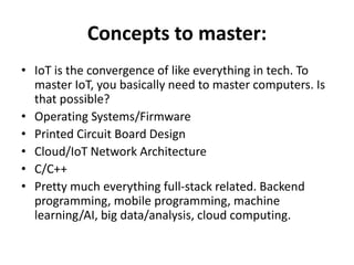
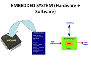
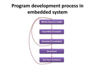
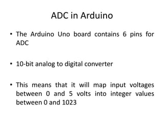
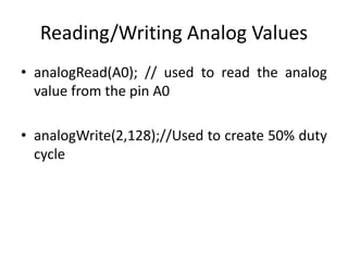
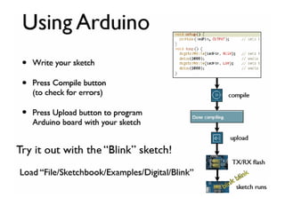
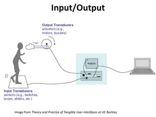
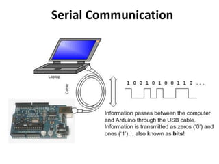
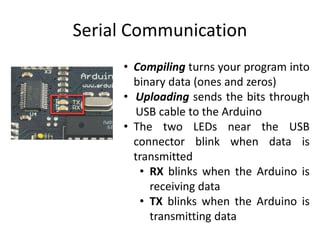
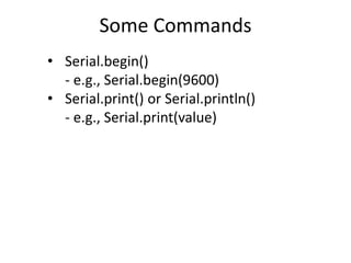
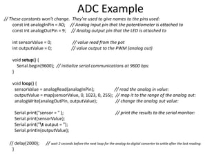
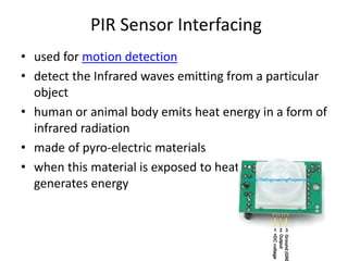
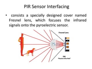
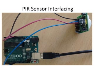
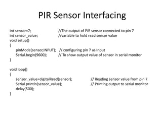
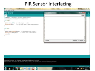
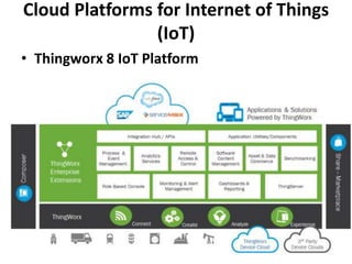
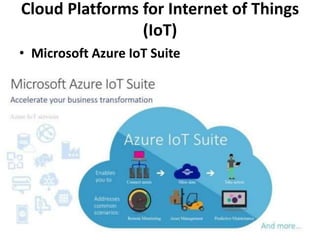
IOT
writing IoT firmware, software, and OS’s for
IoT devices.
There’s 3 distinct parts to any legitimate
IoT product
Wanted to master it
1. Software
2. Hardware
3. Network
First, buy an arduino
• Some cool sensors/lights/led screens or
whatever floats your boat.
• It’s not about building cool stuff, it’s about
learning (both are possible at the same time!).
• If familiar move on to TI sensor tag
Network part
• Most important part.
• The more efficient your data transfers are
from device to device to server to device and
everything in between, the smaller and faster
your device can be.
Concepts to master:
• IoT is the convergence of like everything in tech. To
master IoT, you basically need to master computers. Is
that possible?
• Operating Systems/Firmware
• Printed Circuit Board Design
• Cloud/IoT Network Architecture
• C/C++
• Pretty much everything full-stack related. Backend
programming, mobile programming, machine
learning/AI, big data/analysis, cloud computing.
EMBEDDED SYSTEM (Hardware +
Software)
Program development process in
embedded system
Super-loop Approach
• while(1) { }
• for(;;)
Meet Arduino Uno
What is an Arduino?
Features
• 14 Digital I/O pins
• 6 Analogue inputs
• 6 PWM pins
• USB serial
• 16MHz Clock speed
• 32KB Flash memory
• 2KB SRAM
• 1KB EEPROM
Getting Started
• Check out: http://arduino.cc/en/Guide/HomePage
1. Download & install the Arduino environment (IDE)
(if needed)
2. Connect the board to your computer via the USB cable
3. If needed, install the drivers (if needed)
4. Launch the Arduino IDE
5. Select your board
6. Select your serial port
7. Open the blink example
8. Upload the program
The Arduino IDE
The main features you need to know about are:
• Code area: This is where you will type all your
code
• Info panel: This will show any errors during
compiling or uploading code to your Arduino
• Verify: This allows you to compile your code to
code the Arduino understands. Any mistakes you
have made in the syntax of your code will be
show in the info panel
• Upload: This does the same as verify but will
then send your code to your Arduino if the code
is verified successfully
• Serial Monitor: This will open a window that
allows you to send text to and from an Arduino.
We will use this feature in later lectures.
Before we begin coding
Structure of an Arduino “sketch”
//pins can be thought of as global variables
void setup()
{
// put your setup code here, to run once:
}
void loop() // equivalent to while(1) { }
{
// put your main code here, to run
repeatedly:
}
• setup : It is called only when the Arduino is
powered on or reset. It is used to initialize
variables and pin modes
• loop : The loop functions runs continuously till
the device is powered off. The main logic of
the code goes here. Similar to while (1) for
micro-controller programming.
Minimum code
• A pin on arduino can be set as input or output
by using pinMode function.
• pinMode(13, OUTPUT); // sets pin 13 as
output pin
• pinMode(13, INPUT); // sets pin 13 as input
pin
PinMode
• digitalWrite(13, LOW); // Makes the output
voltage on pin 13 , 0V
• digitalWrite(13, HIGH); // Makes the output
voltage on pin 13 , 5V
• int buttonState = digitalRead(2); // reads the
value of pin 2 in buttonState
Reading/writing digital values
• What is analog ?
• It is continuous range of voltage values (not
just 0 or 5V)
• Why convert to digital ?
• Because our microcontroller only understands
digital.
Analog to Digital Conversion
ADC in Arduino Uno
Converting Analog Value to Digital
• The Arduino Uno board contains 6 pins for
ADC
• 10-bit analog to digital converter
• This means that it will map input voltages
between 0 and 5 volts into integer values
between 0 and 1023
ADC in Arduino
• analogRead(A0); // used to read the analog
value from the pin A0
• analogWrite(2,128);//Used to create 50% duty
cycle
Reading/Writing Analog Values
Input/Output
Image from Theory and Practice of Tangible User Interfaces at UC Berkley
Serial Communication
• Compiling turns your program into
binary data (ones and zeros)
• Uploading sends the bits through
USB cable to the Arduino
• The two LEDs near the USB
connector blink when data is
transmitted
• RX blinks when the Arduino is
receiving data
• TX blinks when the Arduino is
transmitting data
Some Commands
• Serial.begin()
- e.g., Serial.begin(9600)
• Serial.print() or Serial.println()
- e.g., Serial.print(value)
// These constants won't change. They're used to give names to the pins used:
const int analogInPin = A0; // Analog input pin that the potentiometer is attached to
const int analogOutPin = 9; // Analog output pin that the LED is attached to
int sensorValue = 0; // value read from the pot
int outputValue = 0; // value output to the PWM (analog out)
void setup() {
Serial.begin(9600); // initialize serial communications at 9600 bps:
}
void loop() {
sensorValue = analogRead(analogInPin); // read the analog in value:
outputValue = map(sensorValue, 0, 1023, 0, 255); // map it to the range of the analog out:
analogWrite(analogOutPin, outputValue); // change the analog out value:
Serial.print("sensor = " ); // print the results to the serial monitor:
Serial.print(sensorValue);
Serial.print("t output = ");
Serial.println(outputValue);
// delay(2000); // wait 2 seconds before the next loop for the analog-to-digital converter to settle after the last reading:
}
ADC Example
PIR Sensor Interfacing
• used for motion detection
• detect the Infrared waves emitting from a particular
object
• human or animal body emits heat energy in a form of
infrared radiation
• made of pyro-electric materials
• when this material is exposed to heat then, it
generates energy
PIR Sensor Interfacing
• consists a specially designed cover named
Fresnel lens, which focuses the infrared
signals onto the pyroelectric sensor.
PIR Sensor Interfacing
int sensor=7; //The output of PIR sensor connected to pin 7
int sensor_value; //variable to hold read sensor value
void setup()
{
pinMode(sensor,INPUT); // configuring pin 7 as Input
Serial.begin(9600); // To show output value of sensor in serial monitor
}
void loop()
{
sensor_value=digitalRead(sensor); // Reading sensor value from pin 7
Serial.println(sensor_value); // Printing output to serial monitor
delay(500);
}
PIR Sensor Interfacing
Cloud Platforms for Internet of Things
(IoT)
• Thingworx 8 IoT Platform
Cloud Platforms for Internet of Things
(IoT)
• Microsoft Azure IoT Suite
Cloud Platforms for Internet of Things
(IoT)
• Google Cloud’s IoT Platform
• Pricing on Google Cloud is done on a per-
minute basis, which is cheaper than other
platforms.
Cloud Platforms for Internet of Things
(IoT)
• IBM Watson IoT Platform
Cloud Platforms for Internet of Things
(IoT)
• AWS IoT Platform
• Amazon made it much easier for developers to
collect data from sensors and Internet-
connected devices. They help you collect and
send data to the cloud and analyze that
information to provide the ability to manage
devices.
IoT protocols
• Divided in terms of the role they play within
the network.
• Communications (Wi-Fi, Bluetooth),
• Data transmission (MQTT, CoAP, XMPP),
• Security (DTLS), and
• Device management as well as telemetry
MQTT
• Message Queuing Telemetry Transport
• Lightweight messaging protocol that was
developed by IBM and first released in 1999.
• It uses the pub/sub pattern and translates
messages between devices, servers, and
applications.
CoAP
• Which easily translates to HTTP for integration with the existing
Web
• Specialized web transfer protocol for use with constrained nodes
and constrained networks in the Internet of Things.
• CoAP is designed to enable simple, constrained devices to join
the IoT even through constrained networks with low bandwidth
and low availability. The Constrained Application Protocol (CoAP) is
a specialized web transfer protocol for use with constrained nodes
and constrained (e.g., low-power, lossy) networks.
• The nodes often have 8-bit microcontrollers with small amounts of
ROM and RAM, while constrained networks such as IPv6 over Low-
Power Wireless Personal Area Networks (6LoWPANs) often have
high packet error rates and a typical throughput of 10s of kbit/s.
• The protocol is designed for machine- to-machine (M2M)
applications such as smart energy and building automation.

IOT beginnners

  • 1.
    IOT writing IoT firmware,software, and OS’s for IoT devices. There’s 3 distinct parts to any legitimate IoT product Wanted to master it 1. Software 2. Hardware 3. Network
  • 2.
    First, buy anarduino • Some cool sensors/lights/led screens or whatever floats your boat. • It’s not about building cool stuff, it’s about learning (both are possible at the same time!). • If familiar move on to TI sensor tag
  • 3.
    Network part • Mostimportant part. • The more efficient your data transfers are from device to device to server to device and everything in between, the smaller and faster your device can be.
  • 4.
    Concepts to master: •IoT is the convergence of like everything in tech. To master IoT, you basically need to master computers. Is that possible? • Operating Systems/Firmware • Printed Circuit Board Design • Cloud/IoT Network Architecture • C/C++ • Pretty much everything full-stack related. Backend programming, mobile programming, machine learning/AI, big data/analysis, cloud computing.
  • 5.
  • 6.
    Program development processin embedded system
  • 7.
  • 8.
  • 9.
    What is anArduino? Features • 14 Digital I/O pins • 6 Analogue inputs • 6 PWM pins • USB serial • 16MHz Clock speed • 32KB Flash memory • 2KB SRAM • 1KB EEPROM
  • 10.
    Getting Started • Checkout: http://arduino.cc/en/Guide/HomePage 1. Download & install the Arduino environment (IDE) (if needed) 2. Connect the board to your computer via the USB cable 3. If needed, install the drivers (if needed) 4. Launch the Arduino IDE 5. Select your board 6. Select your serial port 7. Open the blink example 8. Upload the program
  • 11.
    The Arduino IDE Themain features you need to know about are: • Code area: This is where you will type all your code • Info panel: This will show any errors during compiling or uploading code to your Arduino • Verify: This allows you to compile your code to code the Arduino understands. Any mistakes you have made in the syntax of your code will be show in the info panel • Upload: This does the same as verify but will then send your code to your Arduino if the code is verified successfully • Serial Monitor: This will open a window that allows you to send text to and from an Arduino. We will use this feature in later lectures.
  • 12.
  • 13.
    Structure of anArduino “sketch” //pins can be thought of as global variables void setup() { // put your setup code here, to run once: } void loop() // equivalent to while(1) { } { // put your main code here, to run repeatedly: }
  • 14.
    • setup :It is called only when the Arduino is powered on or reset. It is used to initialize variables and pin modes • loop : The loop functions runs continuously till the device is powered off. The main logic of the code goes here. Similar to while (1) for micro-controller programming. Minimum code
  • 15.
    • A pinon arduino can be set as input or output by using pinMode function. • pinMode(13, OUTPUT); // sets pin 13 as output pin • pinMode(13, INPUT); // sets pin 13 as input pin PinMode
  • 16.
    • digitalWrite(13, LOW);// Makes the output voltage on pin 13 , 0V • digitalWrite(13, HIGH); // Makes the output voltage on pin 13 , 5V • int buttonState = digitalRead(2); // reads the value of pin 2 in buttonState Reading/writing digital values
  • 17.
    • What isanalog ? • It is continuous range of voltage values (not just 0 or 5V) • Why convert to digital ? • Because our microcontroller only understands digital. Analog to Digital Conversion
  • 18.
  • 19.
  • 20.
    • The ArduinoUno board contains 6 pins for ADC • 10-bit analog to digital converter • This means that it will map input voltages between 0 and 5 volts into integer values between 0 and 1023 ADC in Arduino
  • 21.
    • analogRead(A0); //used to read the analog value from the pin A0 • analogWrite(2,128);//Used to create 50% duty cycle Reading/Writing Analog Values
  • 23.
    Input/Output Image from Theoryand Practice of Tangible User Interfaces at UC Berkley
  • 24.
  • 25.
    Serial Communication • Compilingturns your program into binary data (ones and zeros) • Uploading sends the bits through USB cable to the Arduino • The two LEDs near the USB connector blink when data is transmitted • RX blinks when the Arduino is receiving data • TX blinks when the Arduino is transmitting data
  • 26.
    Some Commands • Serial.begin() -e.g., Serial.begin(9600) • Serial.print() or Serial.println() - e.g., Serial.print(value)
  • 27.
    // These constantswon't change. They're used to give names to the pins used: const int analogInPin = A0; // Analog input pin that the potentiometer is attached to const int analogOutPin = 9; // Analog output pin that the LED is attached to int sensorValue = 0; // value read from the pot int outputValue = 0; // value output to the PWM (analog out) void setup() { Serial.begin(9600); // initialize serial communications at 9600 bps: } void loop() { sensorValue = analogRead(analogInPin); // read the analog in value: outputValue = map(sensorValue, 0, 1023, 0, 255); // map it to the range of the analog out: analogWrite(analogOutPin, outputValue); // change the analog out value: Serial.print("sensor = " ); // print the results to the serial monitor: Serial.print(sensorValue); Serial.print("t output = "); Serial.println(outputValue); // delay(2000); // wait 2 seconds before the next loop for the analog-to-digital converter to settle after the last reading: } ADC Example
  • 28.
    PIR Sensor Interfacing •used for motion detection • detect the Infrared waves emitting from a particular object • human or animal body emits heat energy in a form of infrared radiation • made of pyro-electric materials • when this material is exposed to heat then, it generates energy
  • 29.
    PIR Sensor Interfacing •consists a specially designed cover named Fresnel lens, which focuses the infrared signals onto the pyroelectric sensor.
  • 30.
  • 31.
    PIR Sensor Interfacing intsensor=7; //The output of PIR sensor connected to pin 7 int sensor_value; //variable to hold read sensor value void setup() { pinMode(sensor,INPUT); // configuring pin 7 as Input Serial.begin(9600); // To show output value of sensor in serial monitor } void loop() { sensor_value=digitalRead(sensor); // Reading sensor value from pin 7 Serial.println(sensor_value); // Printing output to serial monitor delay(500); }
  • 32.
  • 33.
    Cloud Platforms forInternet of Things (IoT) • Thingworx 8 IoT Platform
  • 34.
    Cloud Platforms forInternet of Things (IoT) • Microsoft Azure IoT Suite
  • 35.
    Cloud Platforms forInternet of Things (IoT) • Google Cloud’s IoT Platform • Pricing on Google Cloud is done on a per- minute basis, which is cheaper than other platforms.
  • 36.
    Cloud Platforms forInternet of Things (IoT) • IBM Watson IoT Platform
  • 37.
    Cloud Platforms forInternet of Things (IoT) • AWS IoT Platform • Amazon made it much easier for developers to collect data from sensors and Internet- connected devices. They help you collect and send data to the cloud and analyze that information to provide the ability to manage devices.
  • 38.
    IoT protocols • Dividedin terms of the role they play within the network. • Communications (Wi-Fi, Bluetooth), • Data transmission (MQTT, CoAP, XMPP), • Security (DTLS), and • Device management as well as telemetry
  • 39.
    MQTT • Message QueuingTelemetry Transport • Lightweight messaging protocol that was developed by IBM and first released in 1999. • It uses the pub/sub pattern and translates messages between devices, servers, and applications.
  • 40.
    CoAP • Which easilytranslates to HTTP for integration with the existing Web • Specialized web transfer protocol for use with constrained nodes and constrained networks in the Internet of Things. • CoAP is designed to enable simple, constrained devices to join the IoT even through constrained networks with low bandwidth and low availability. The Constrained Application Protocol (CoAP) is a specialized web transfer protocol for use with constrained nodes and constrained (e.g., low-power, lossy) networks. • The nodes often have 8-bit microcontrollers with small amounts of ROM and RAM, while constrained networks such as IPv6 over Low- Power Wireless Personal Area Networks (6LoWPANs) often have high packet error rates and a typical throughput of 10s of kbit/s. • The protocol is designed for machine- to-machine (M2M) applications such as smart energy and building automation.

Editor's Notes

  • #13 Mention device manager for COM ports
  • #14 Before you show the NB, switch to desktop view and do it together with them