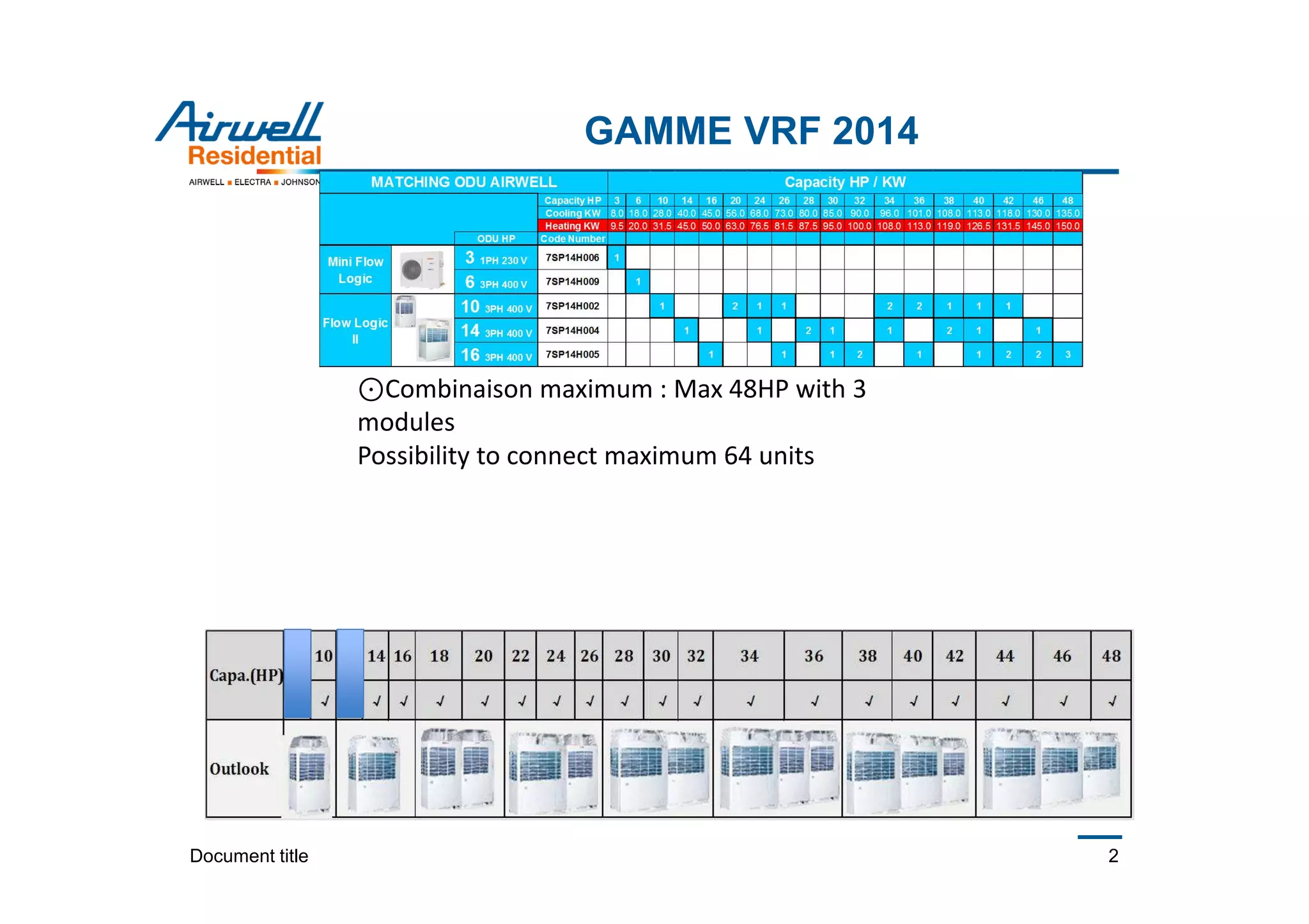
This document provides information on a commercial VRF range for 2014, including:
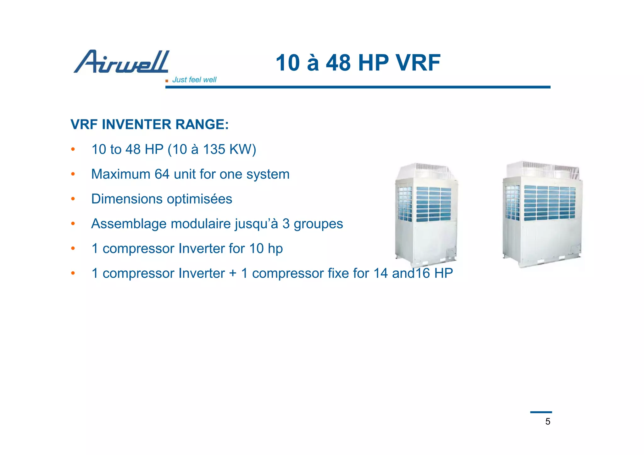
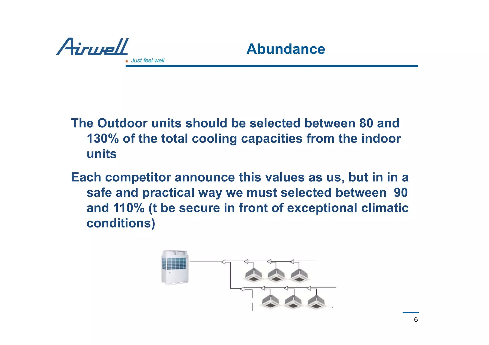
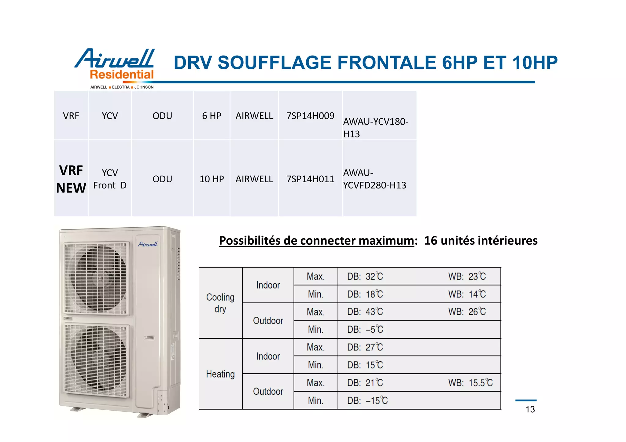
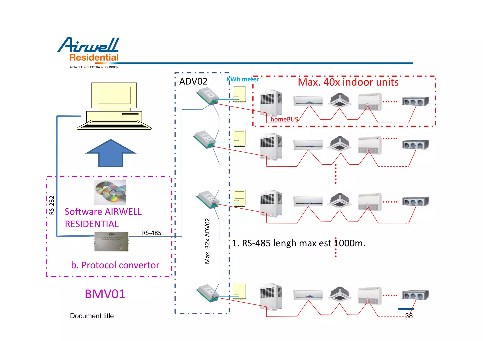
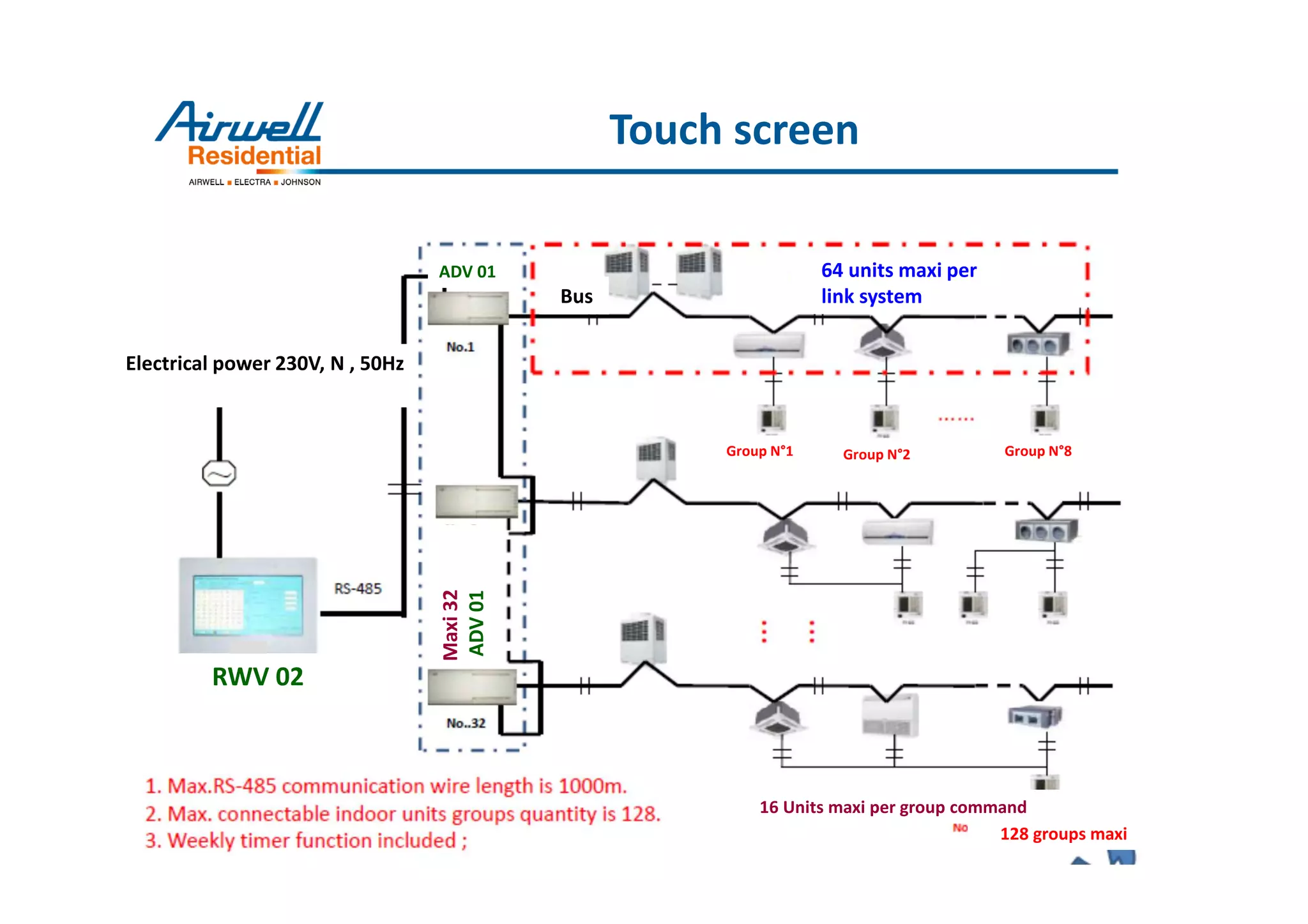
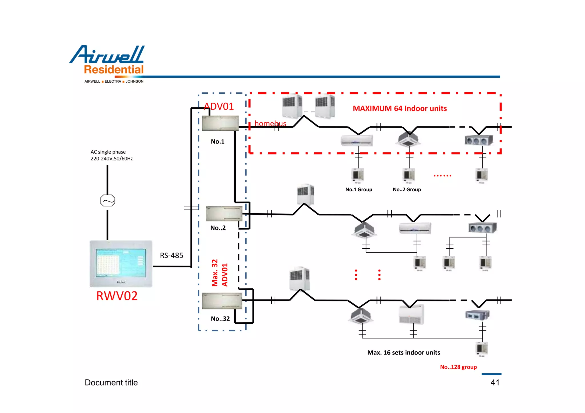
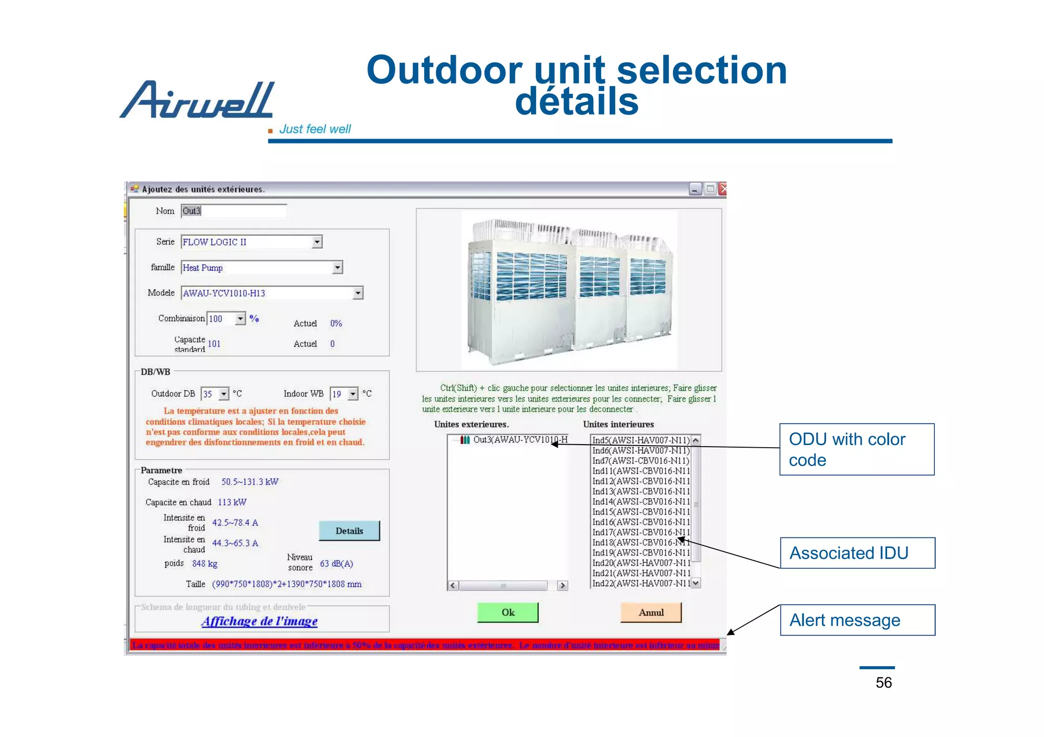
- Outdoor units can connect up to 48HP with 3 modules and a maximum of 64 indoor units.
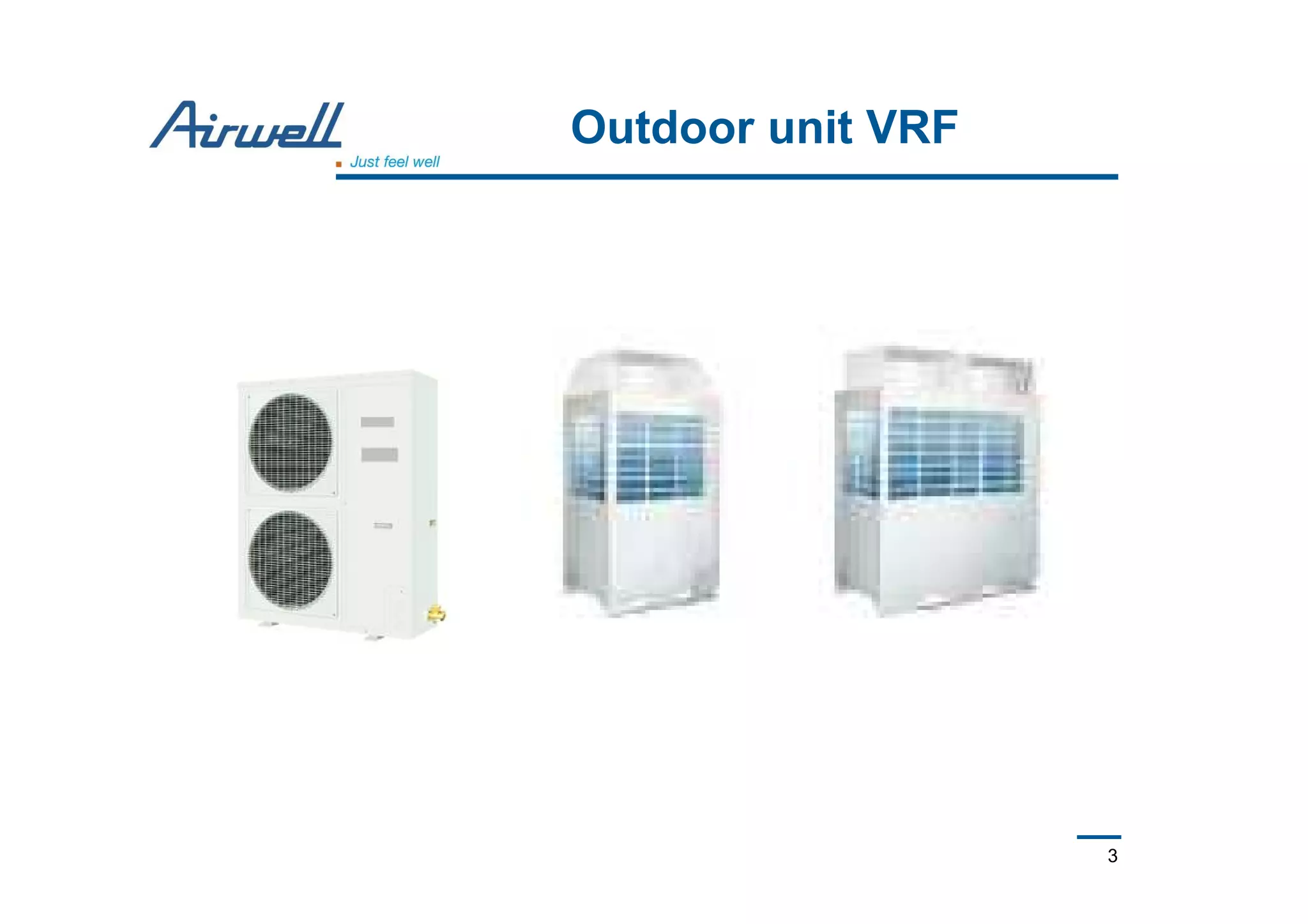
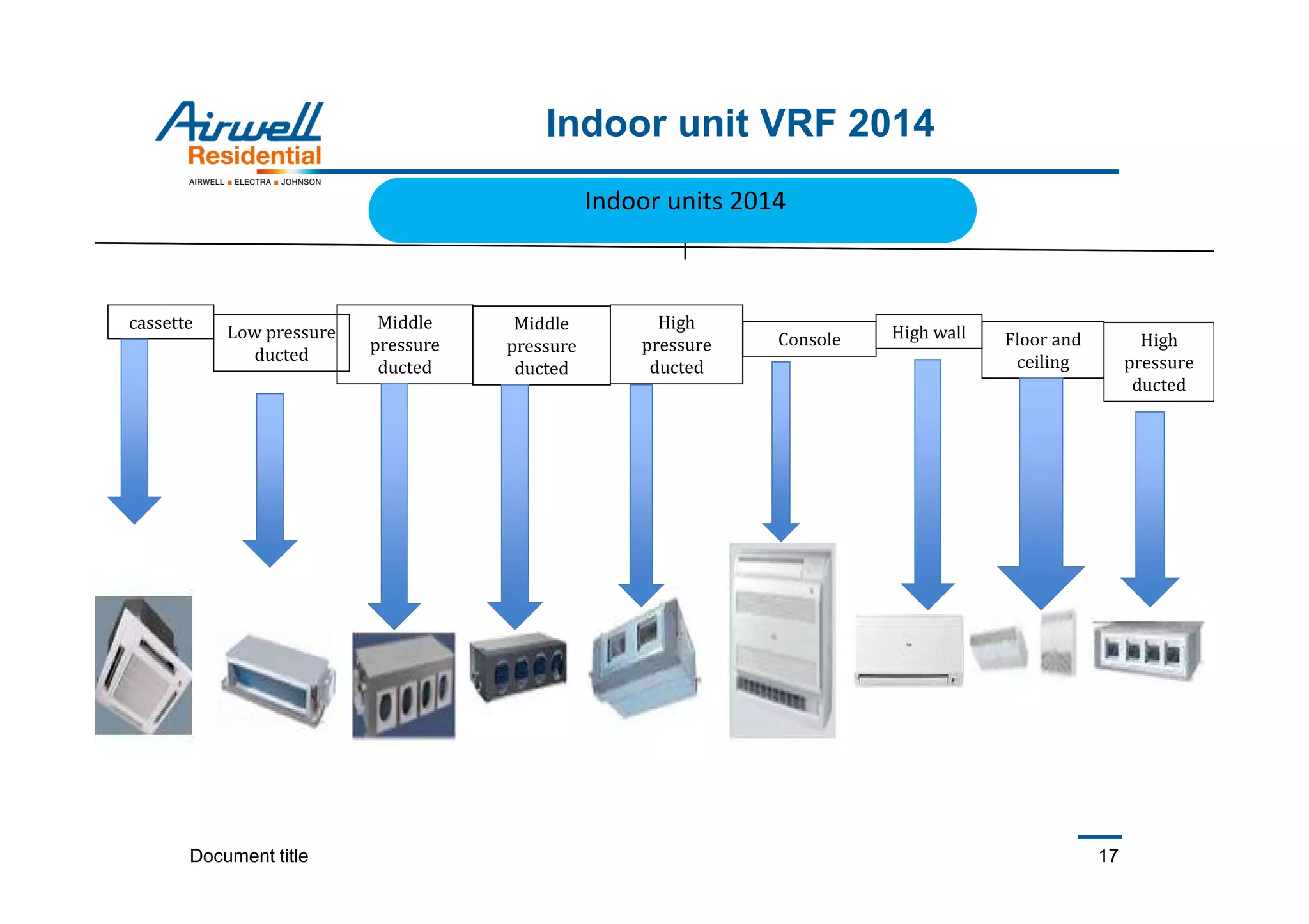
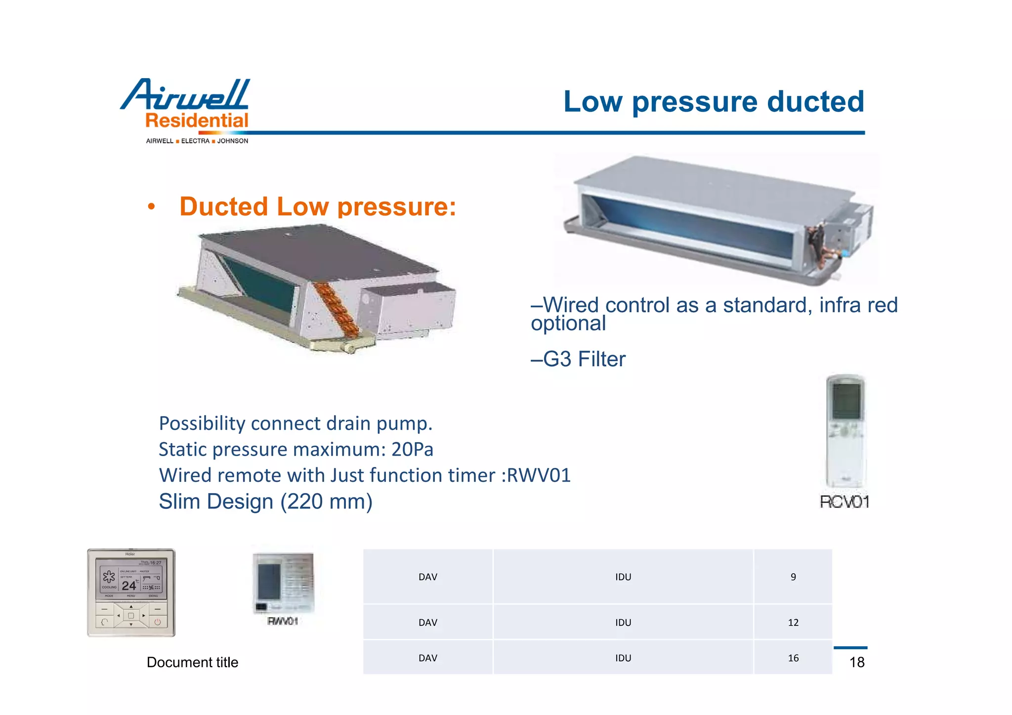
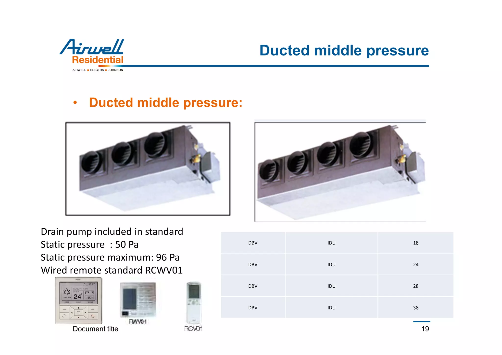
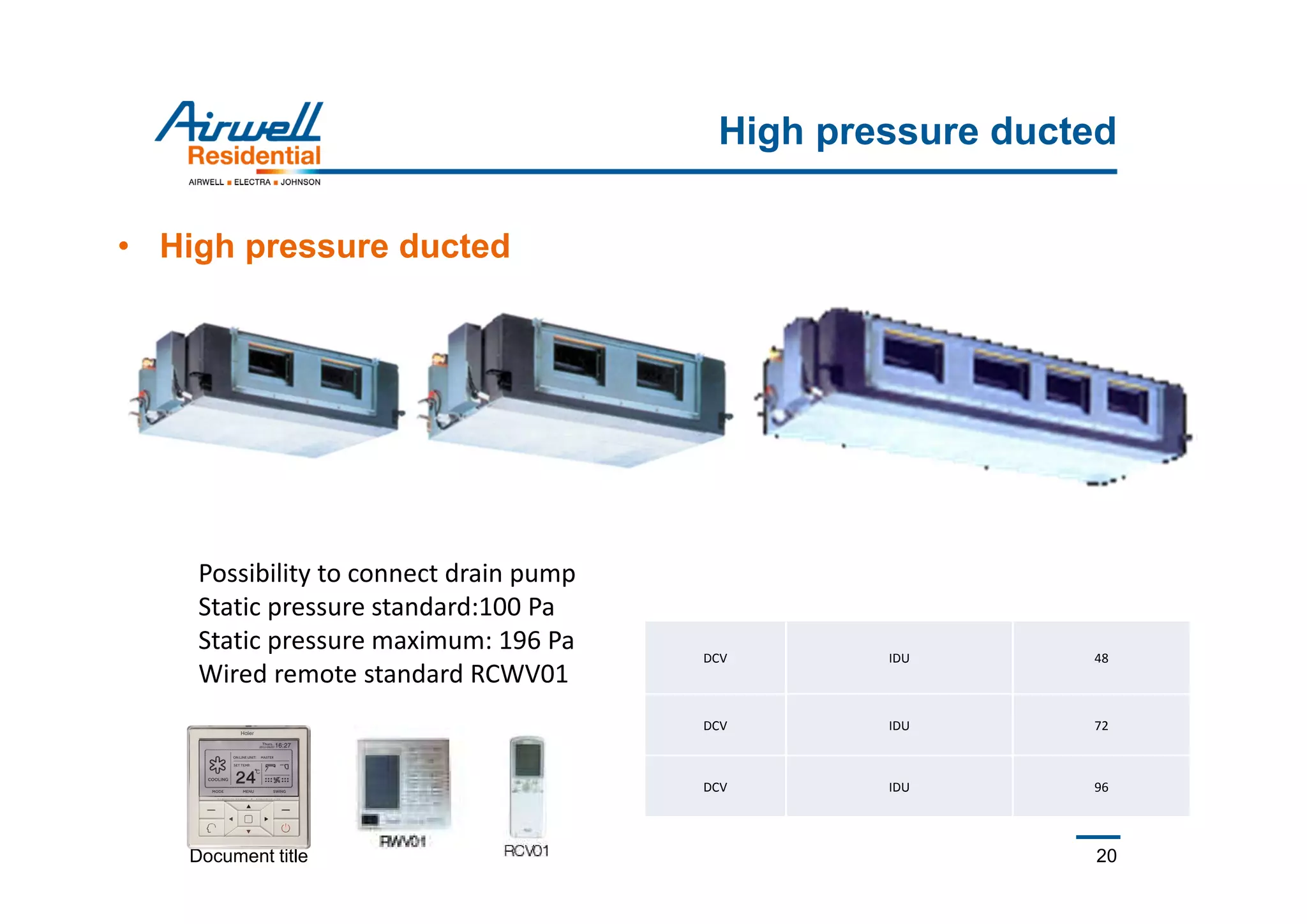
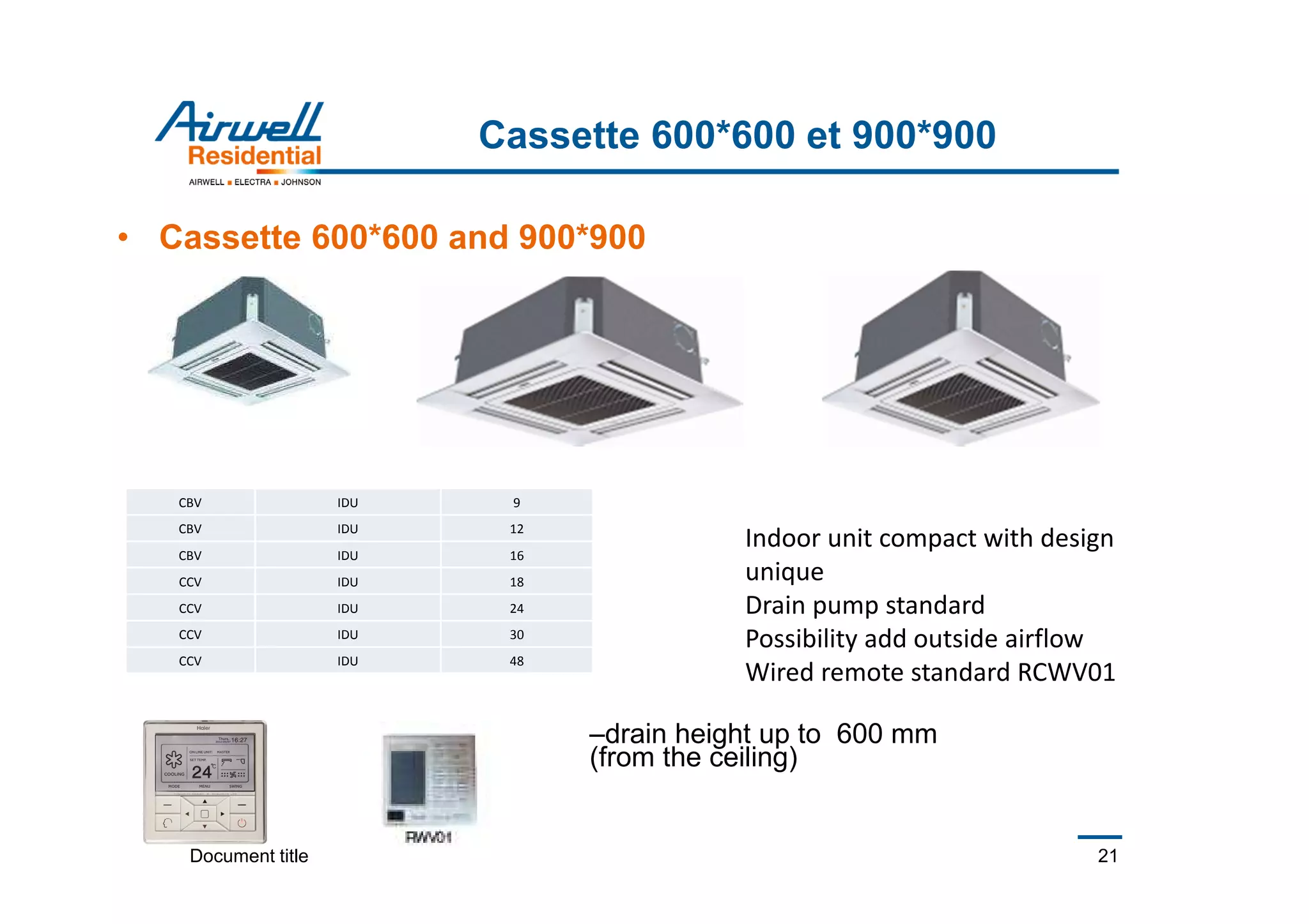
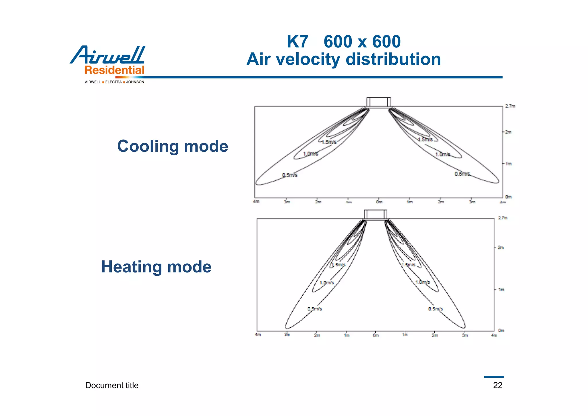
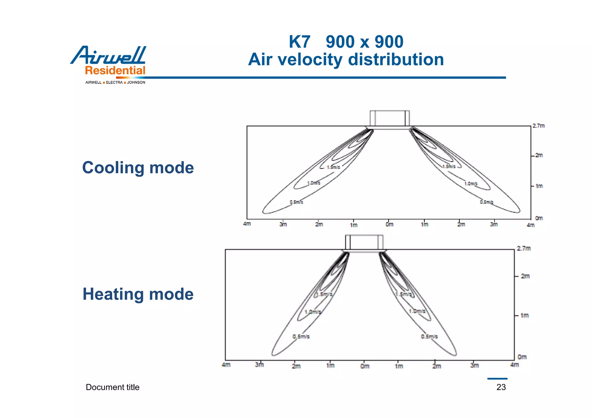
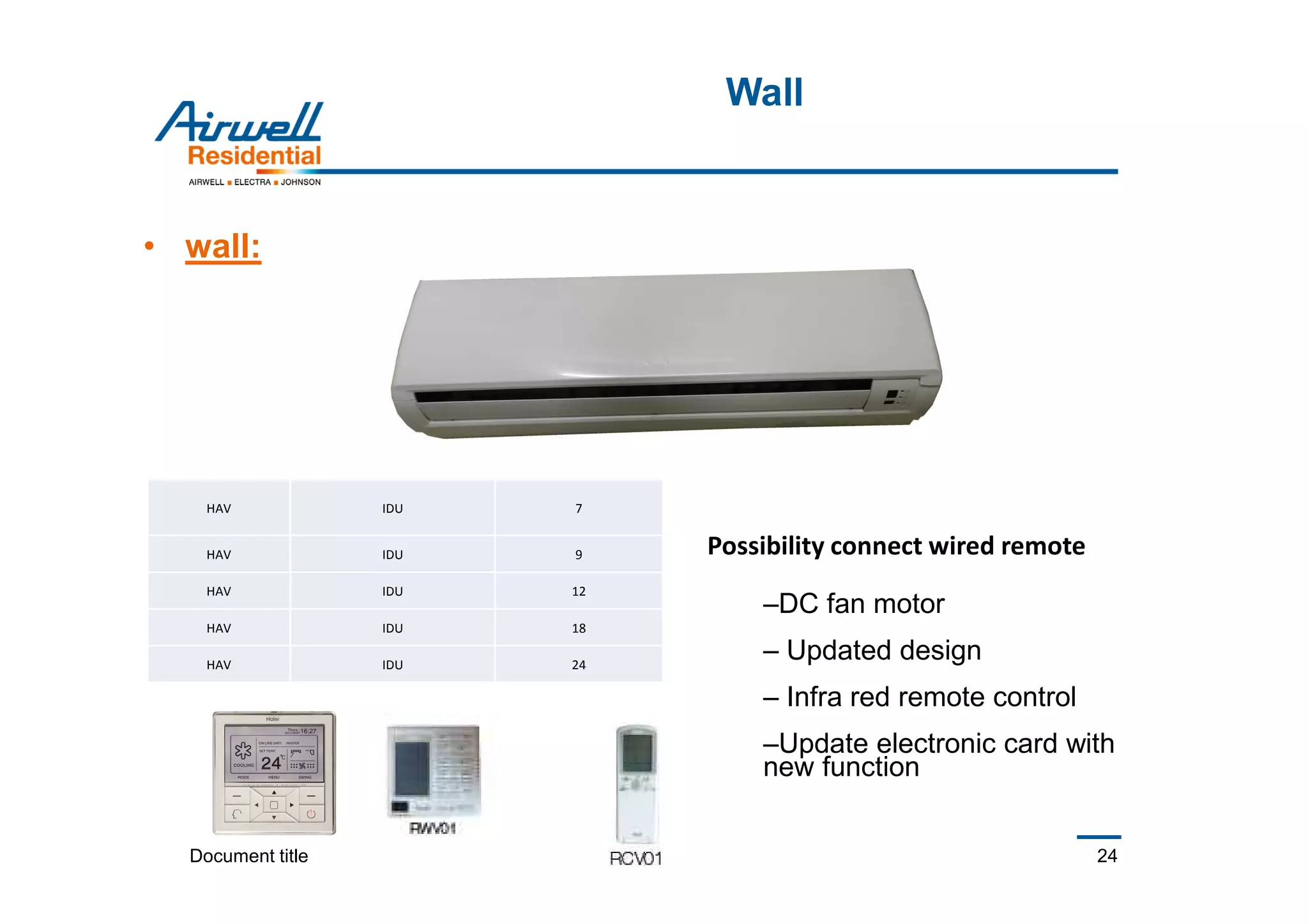
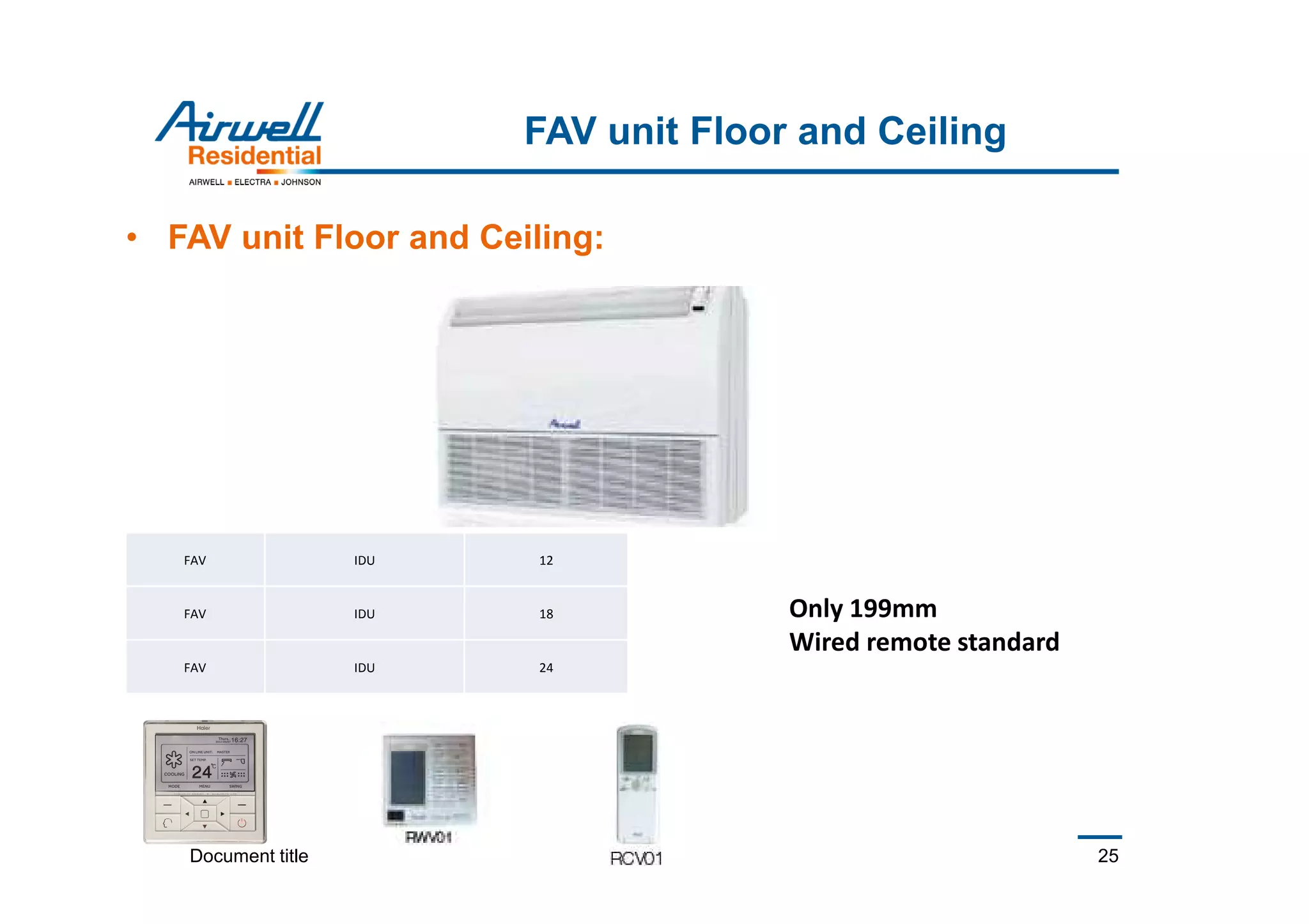
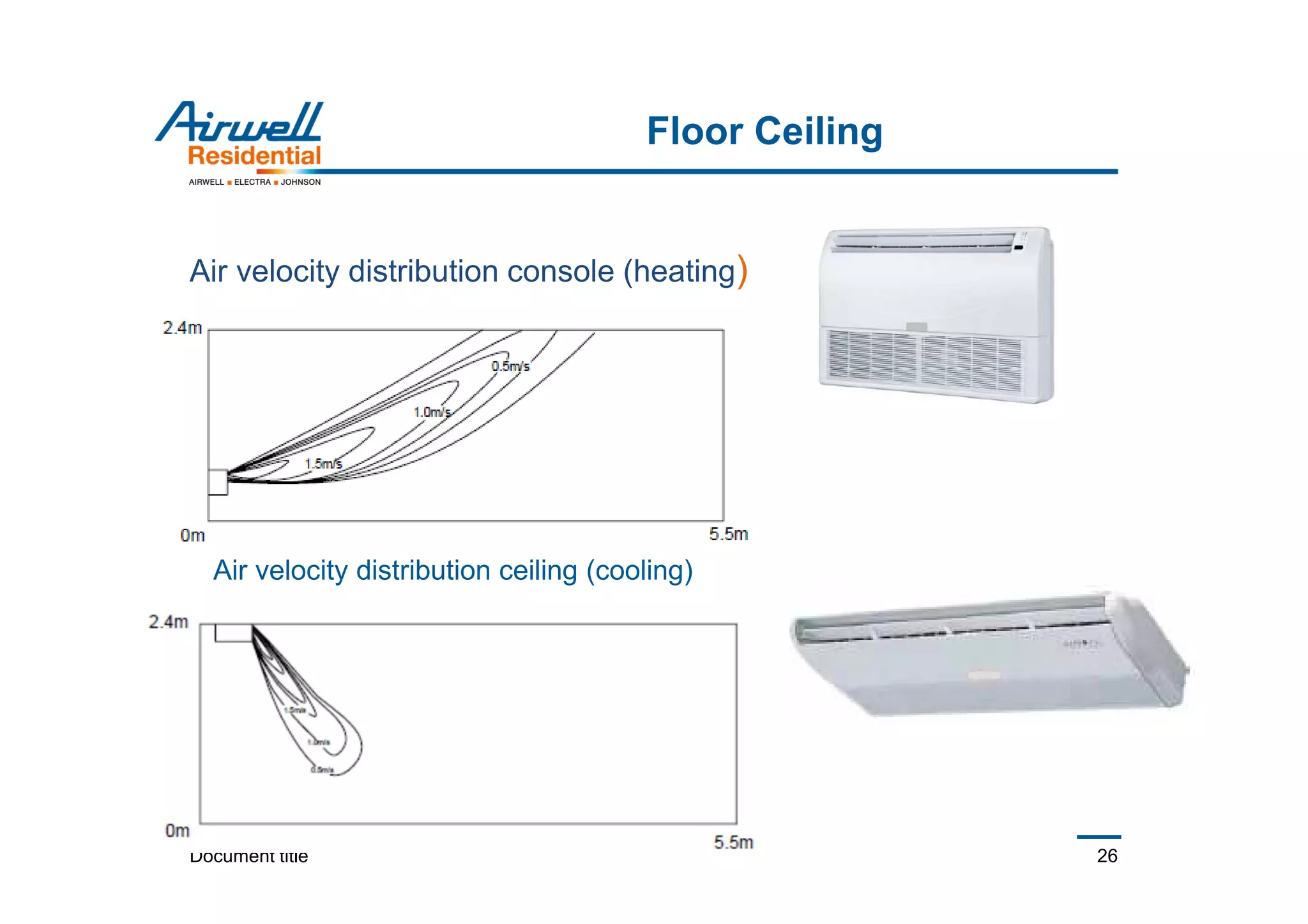
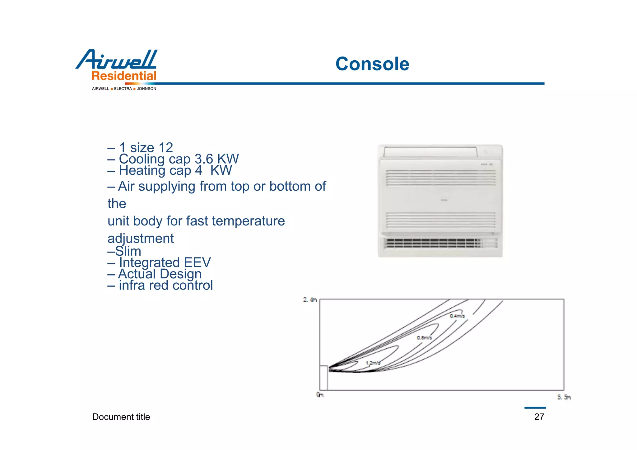
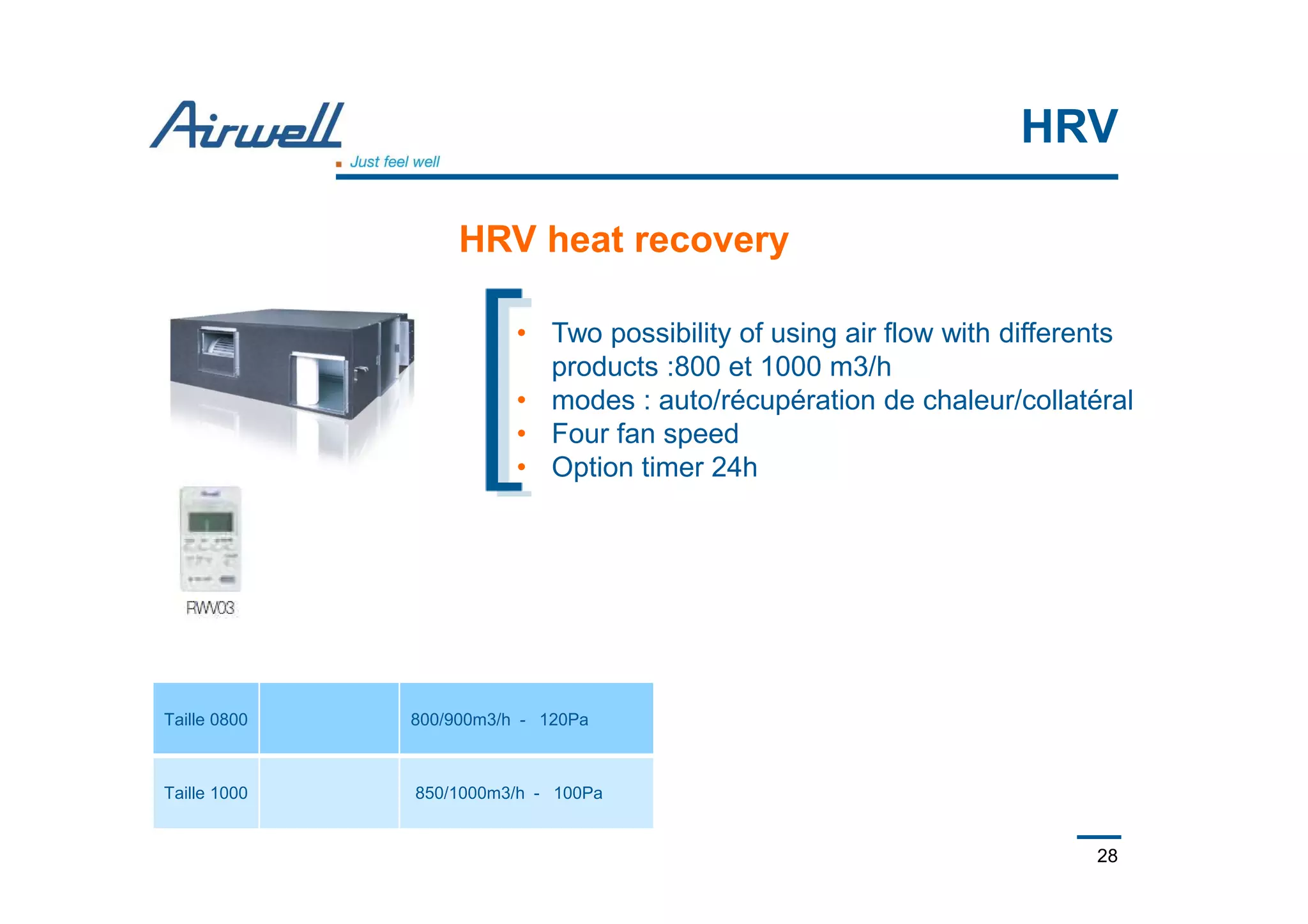
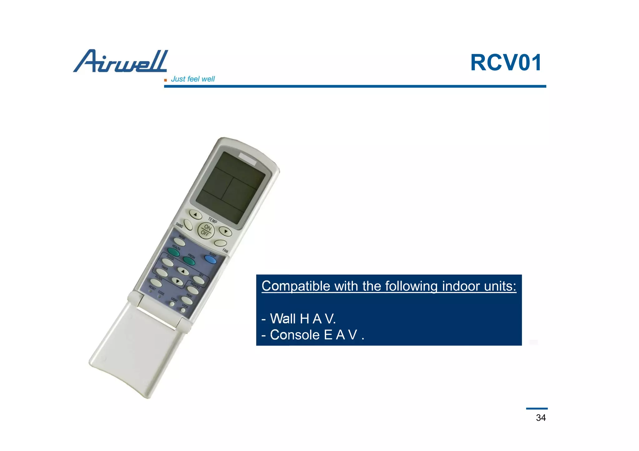
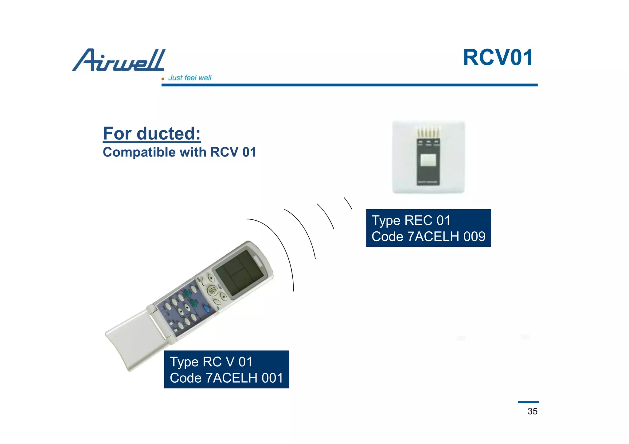
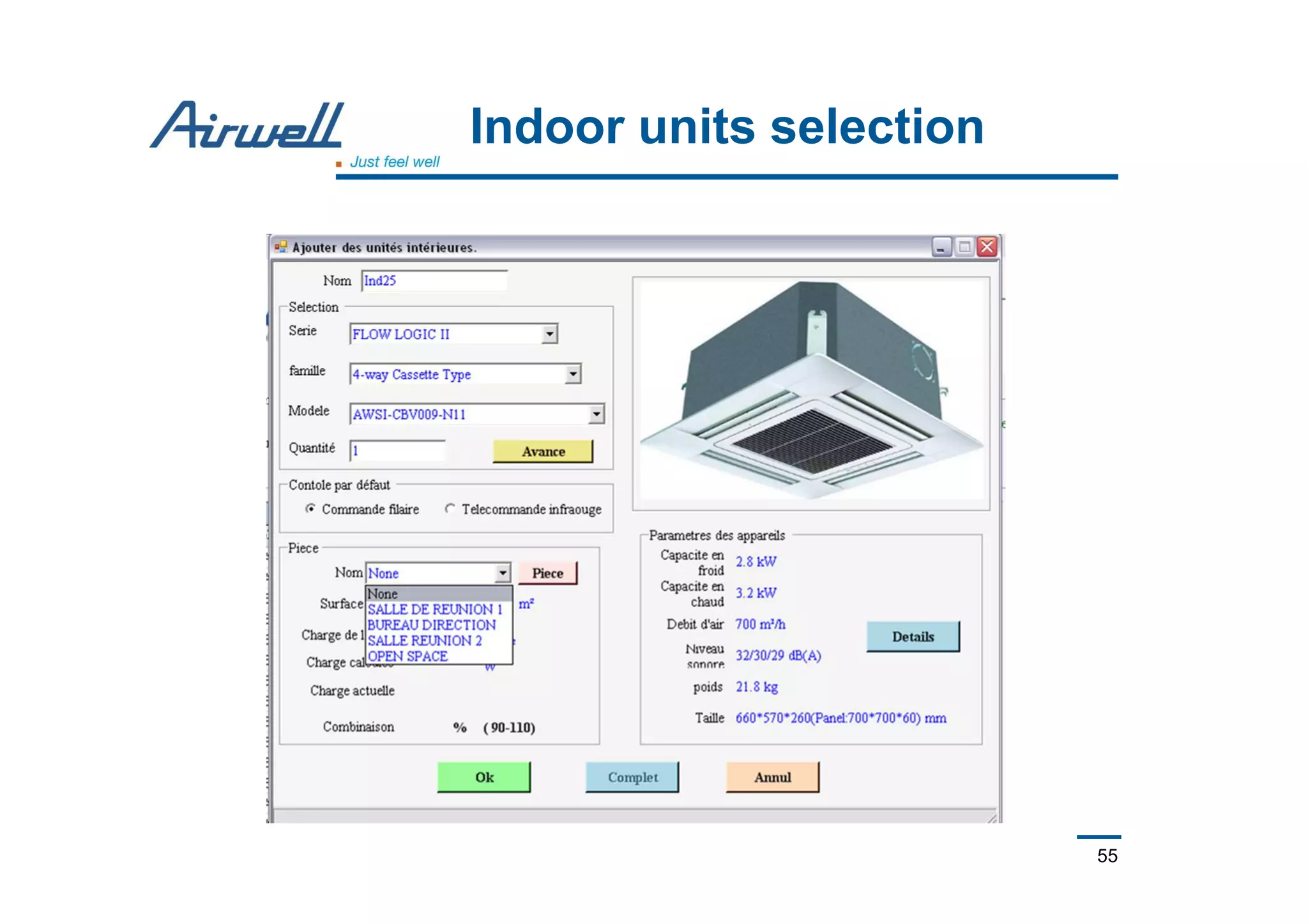
- Indoor unit options include cassettes, floor/ceiling units, ducted units, walls splits, and more.
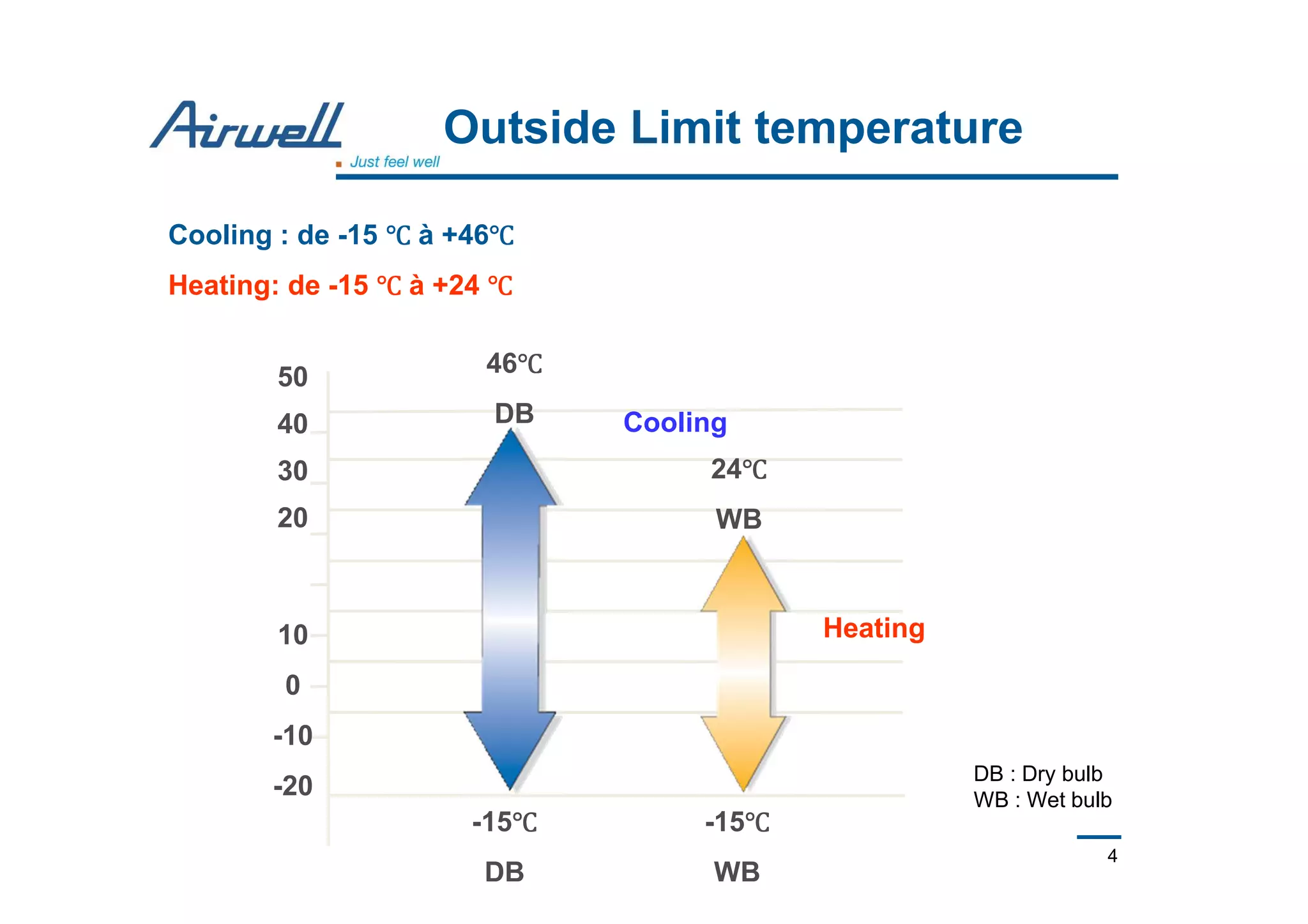
- Outdoor units can operate from -15°C to +46°C in cooling mode and -15°C to +24°C in heating mode.
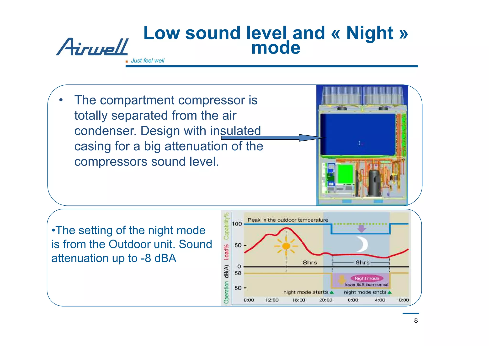
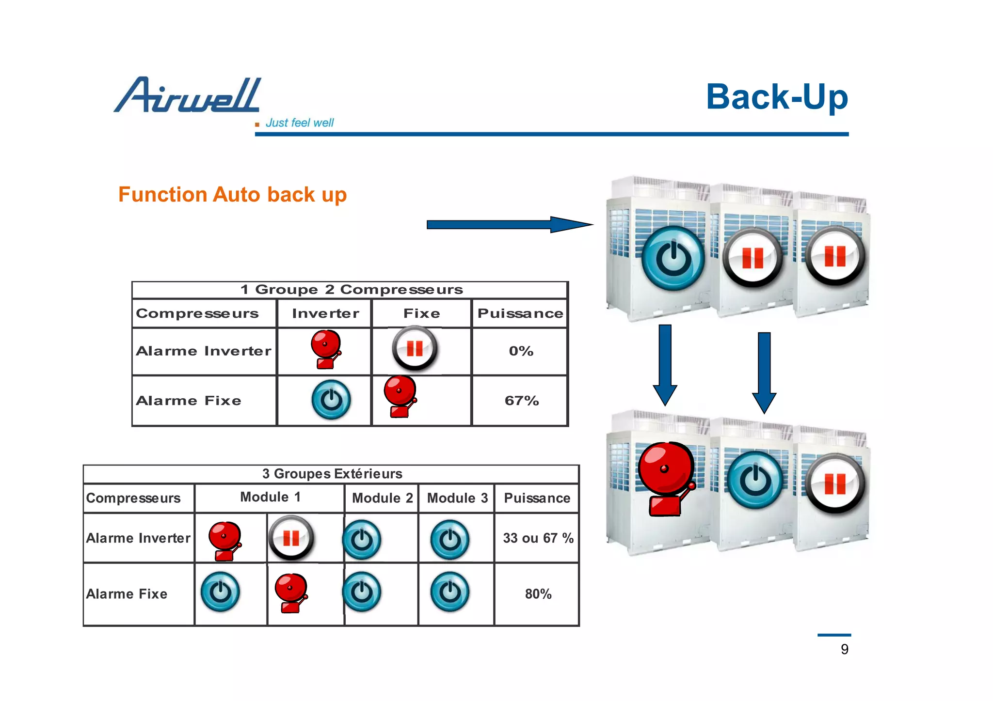
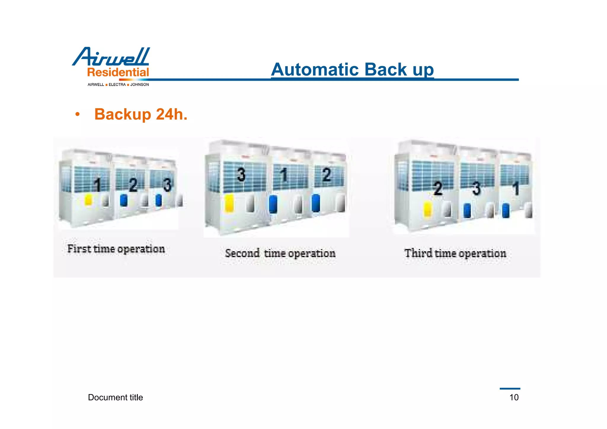
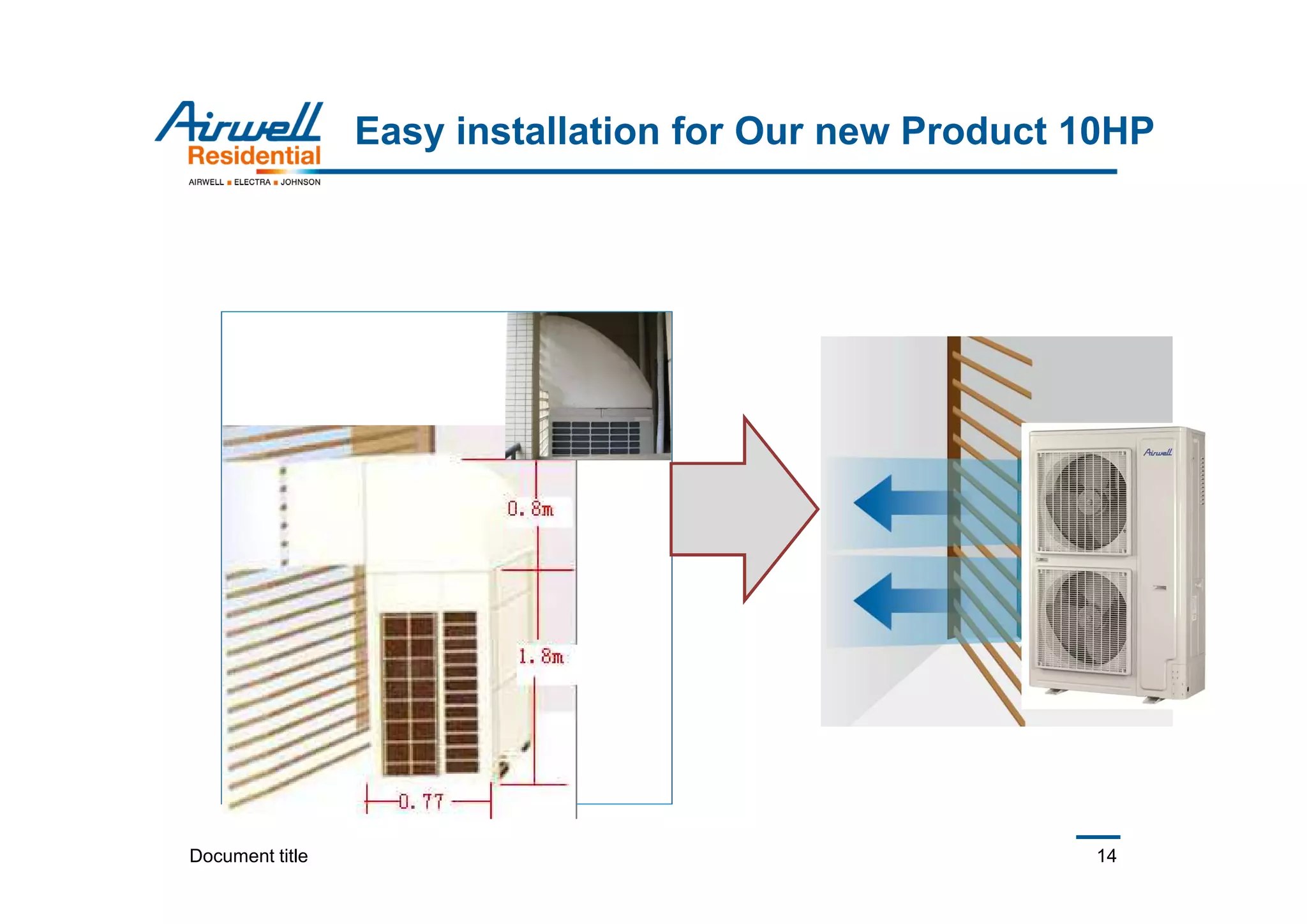
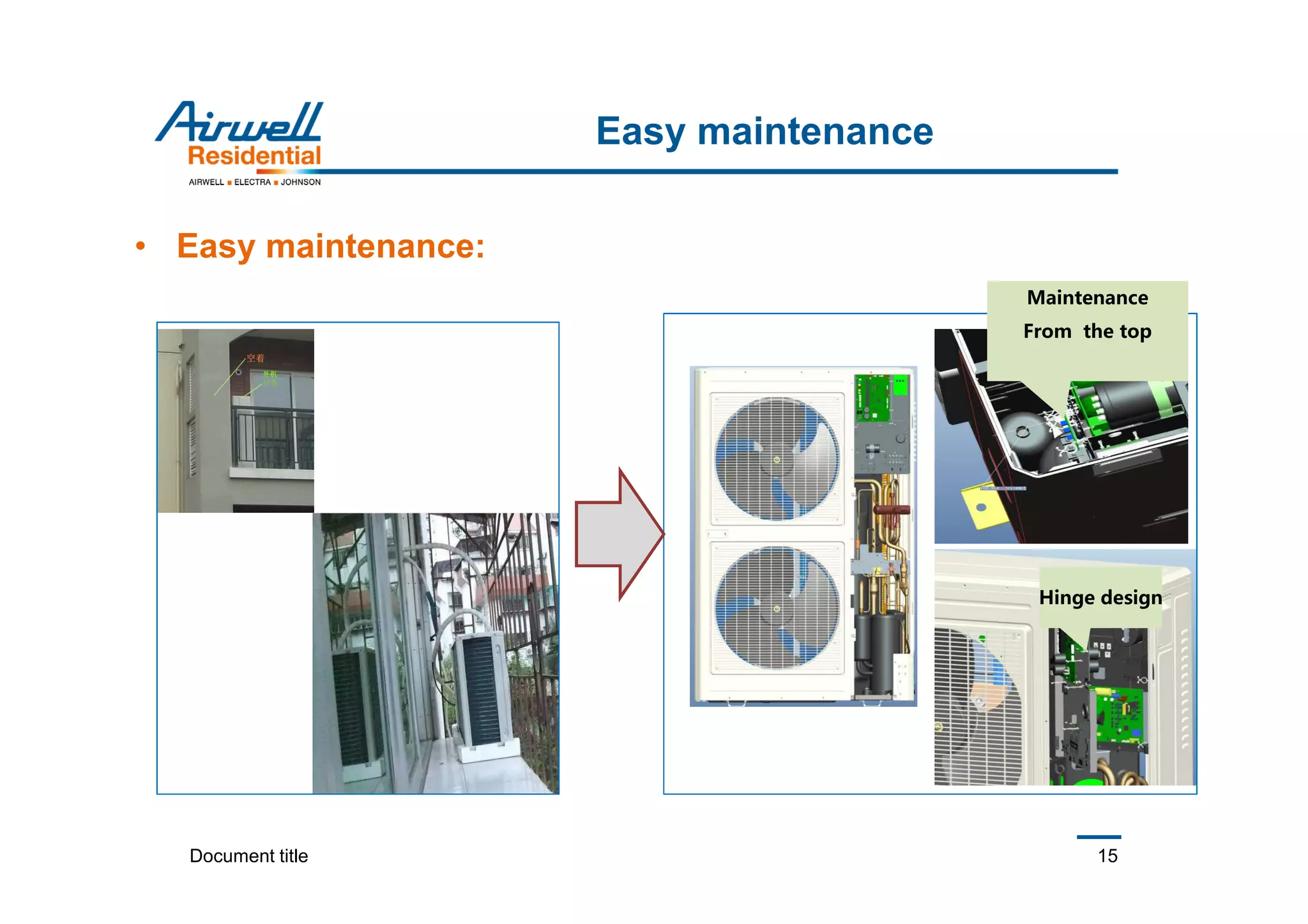
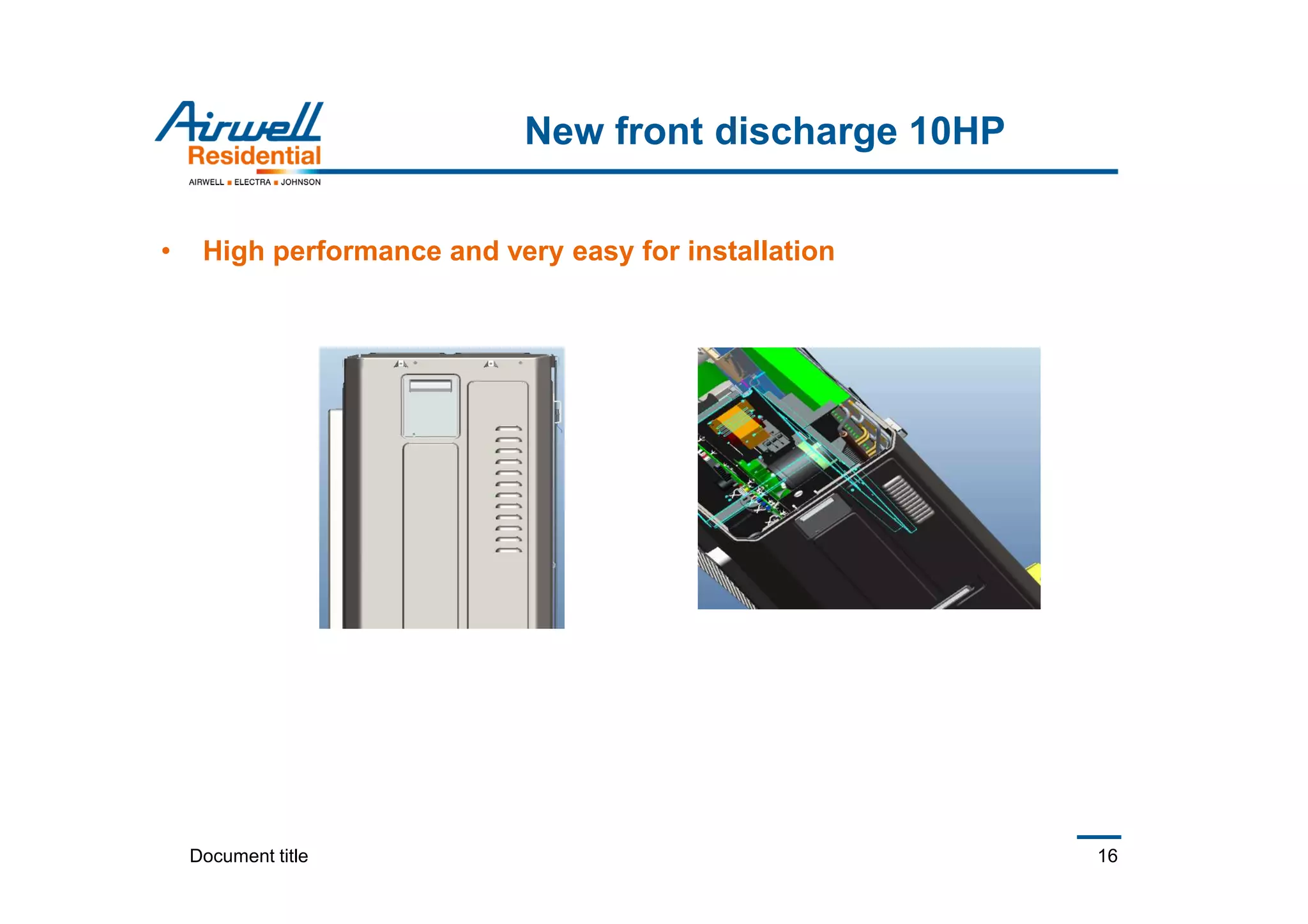
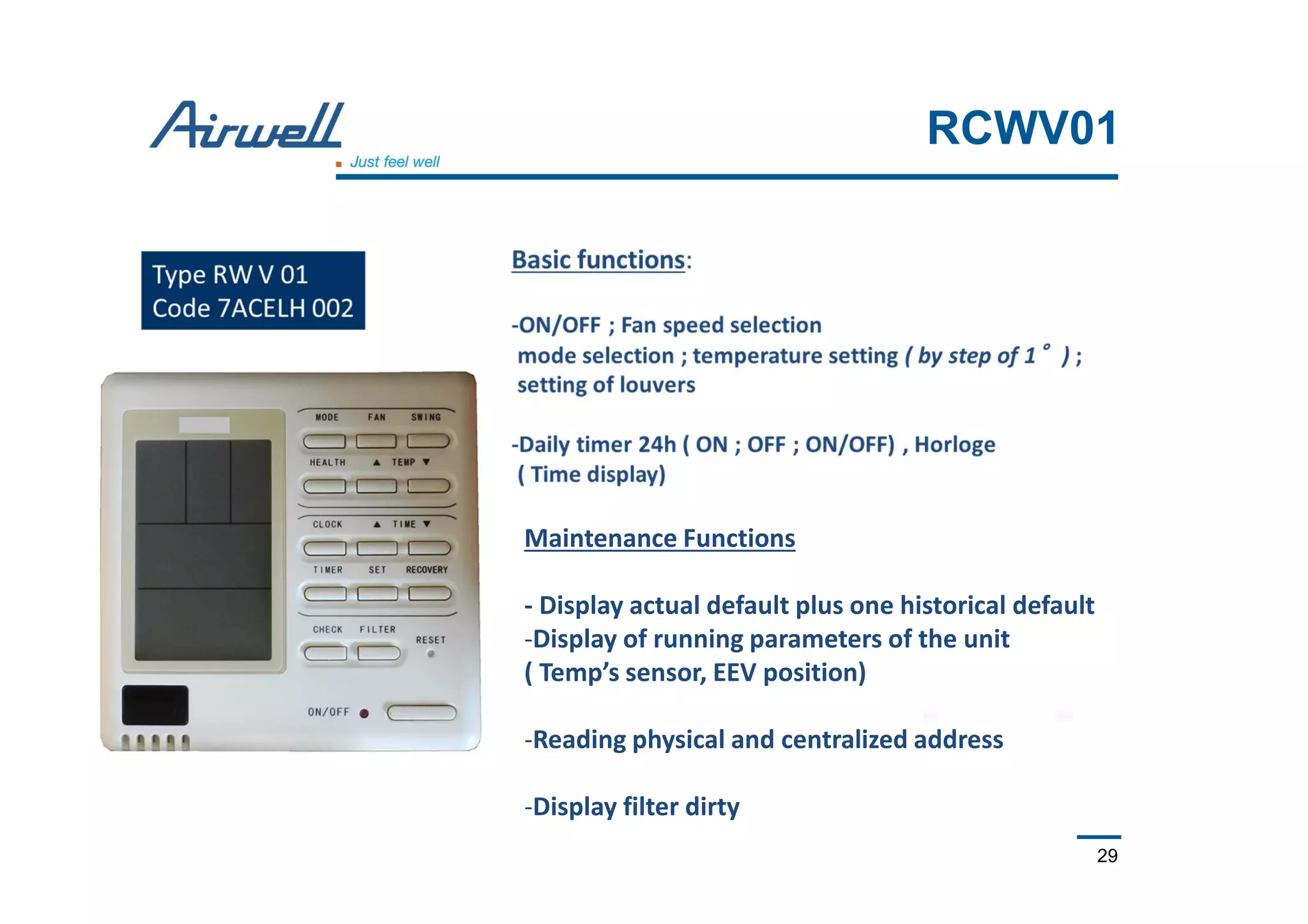
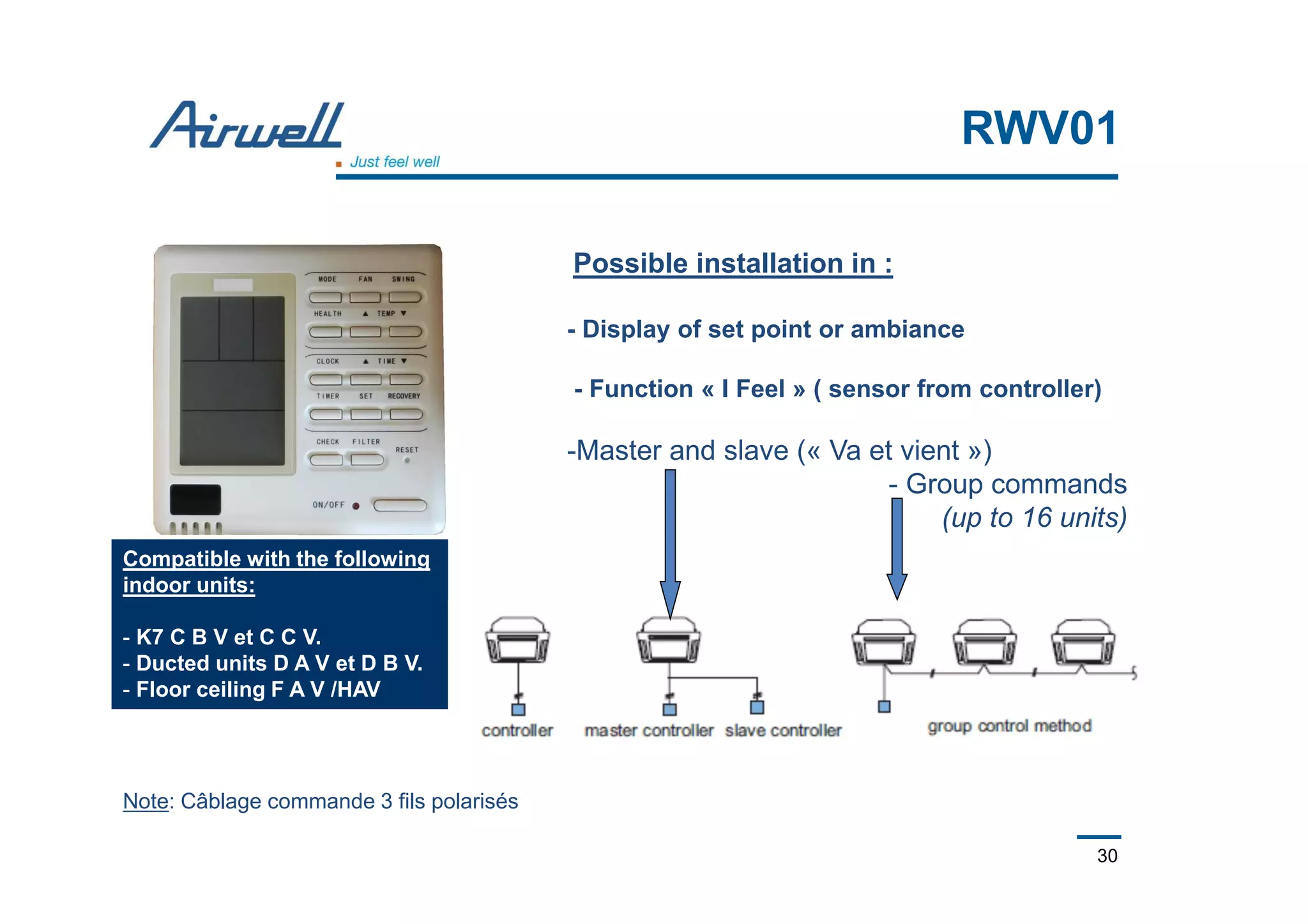
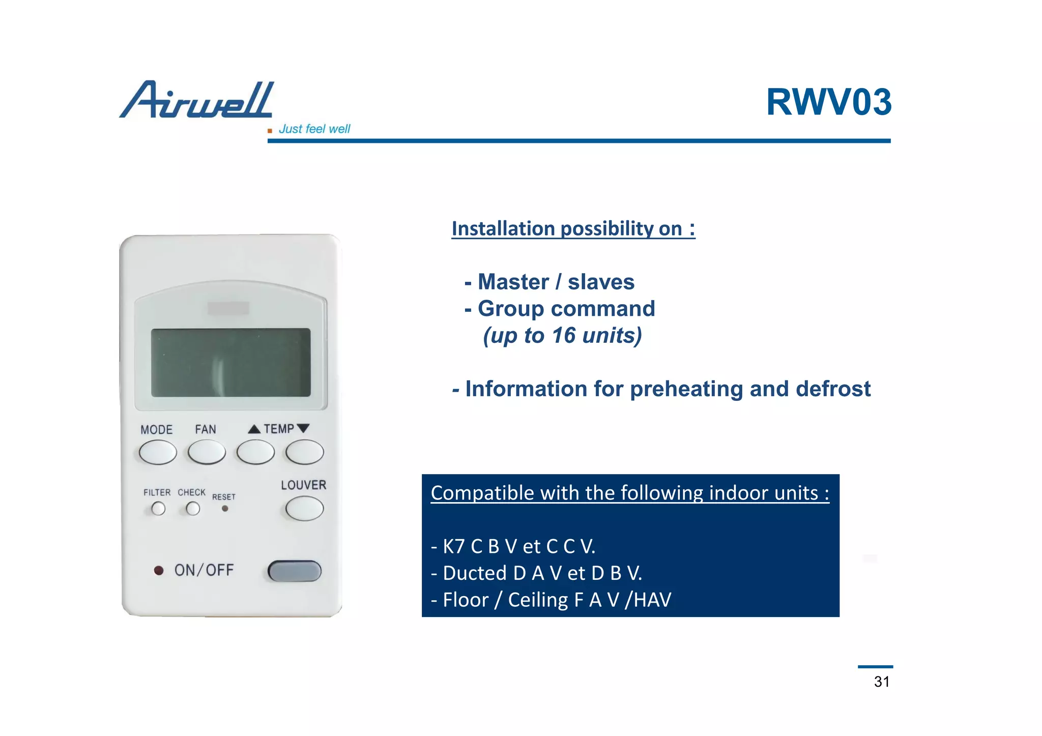
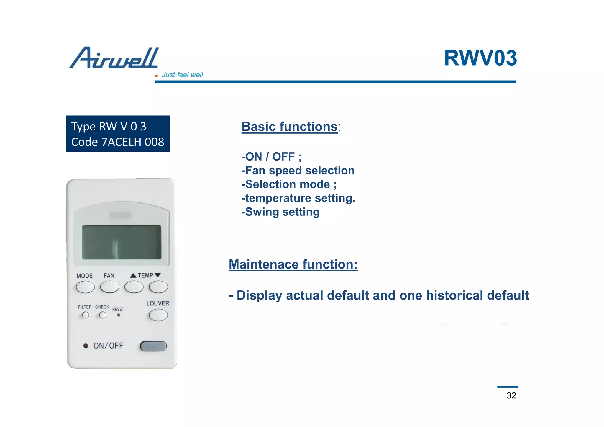
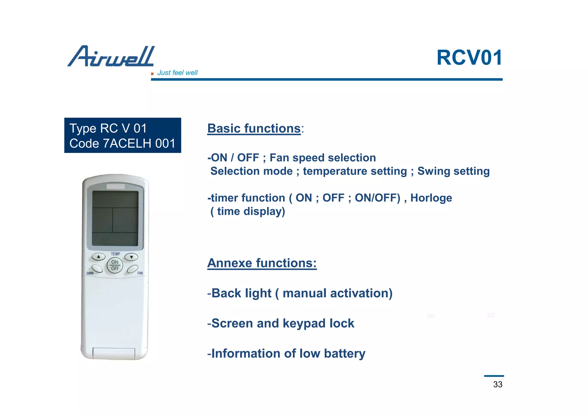
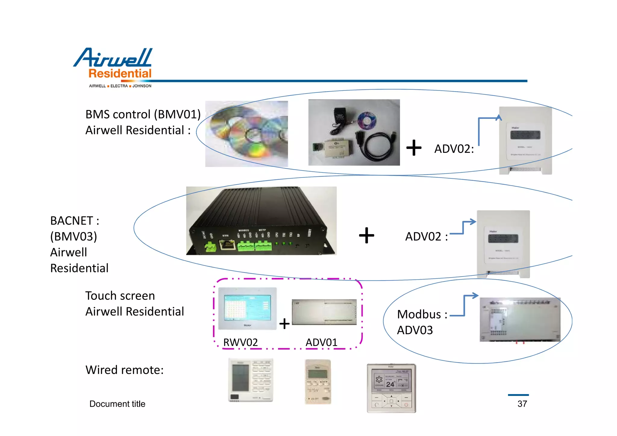
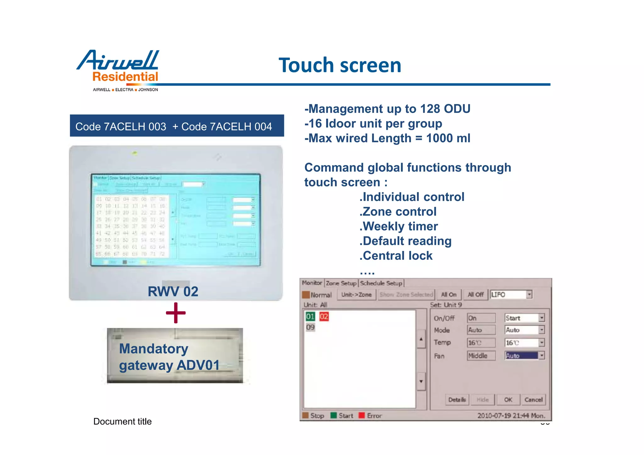
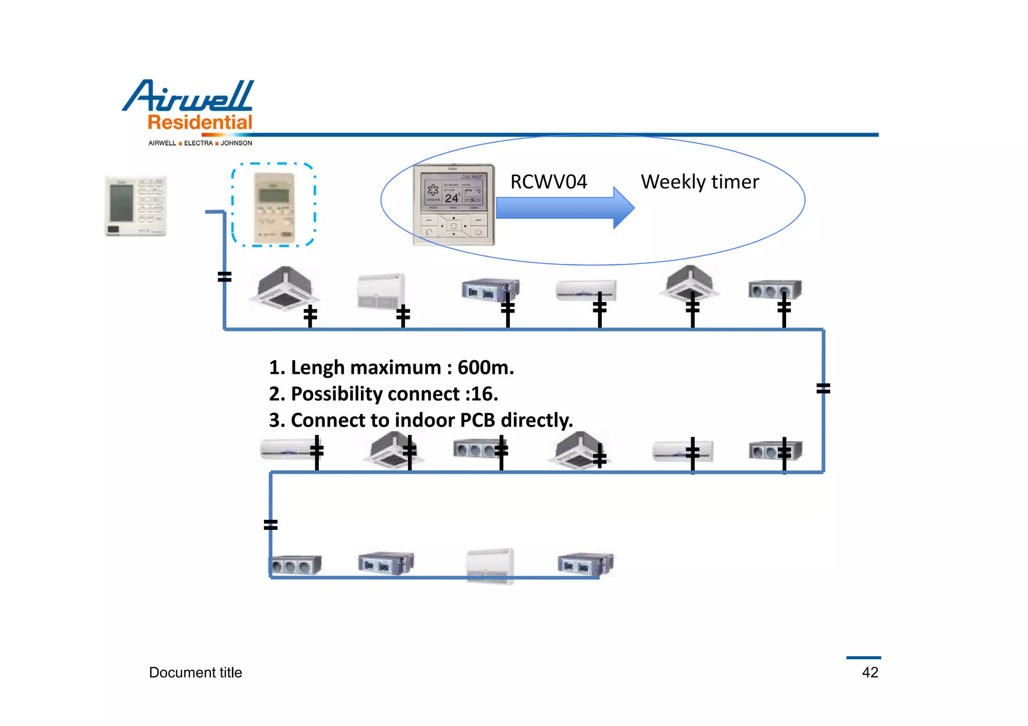
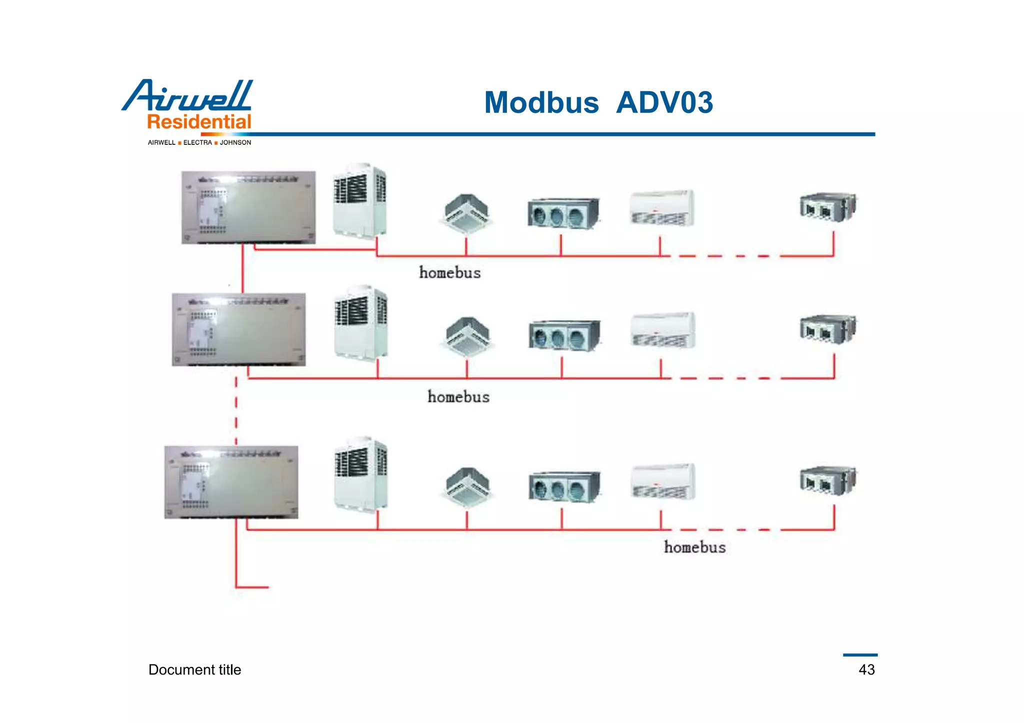
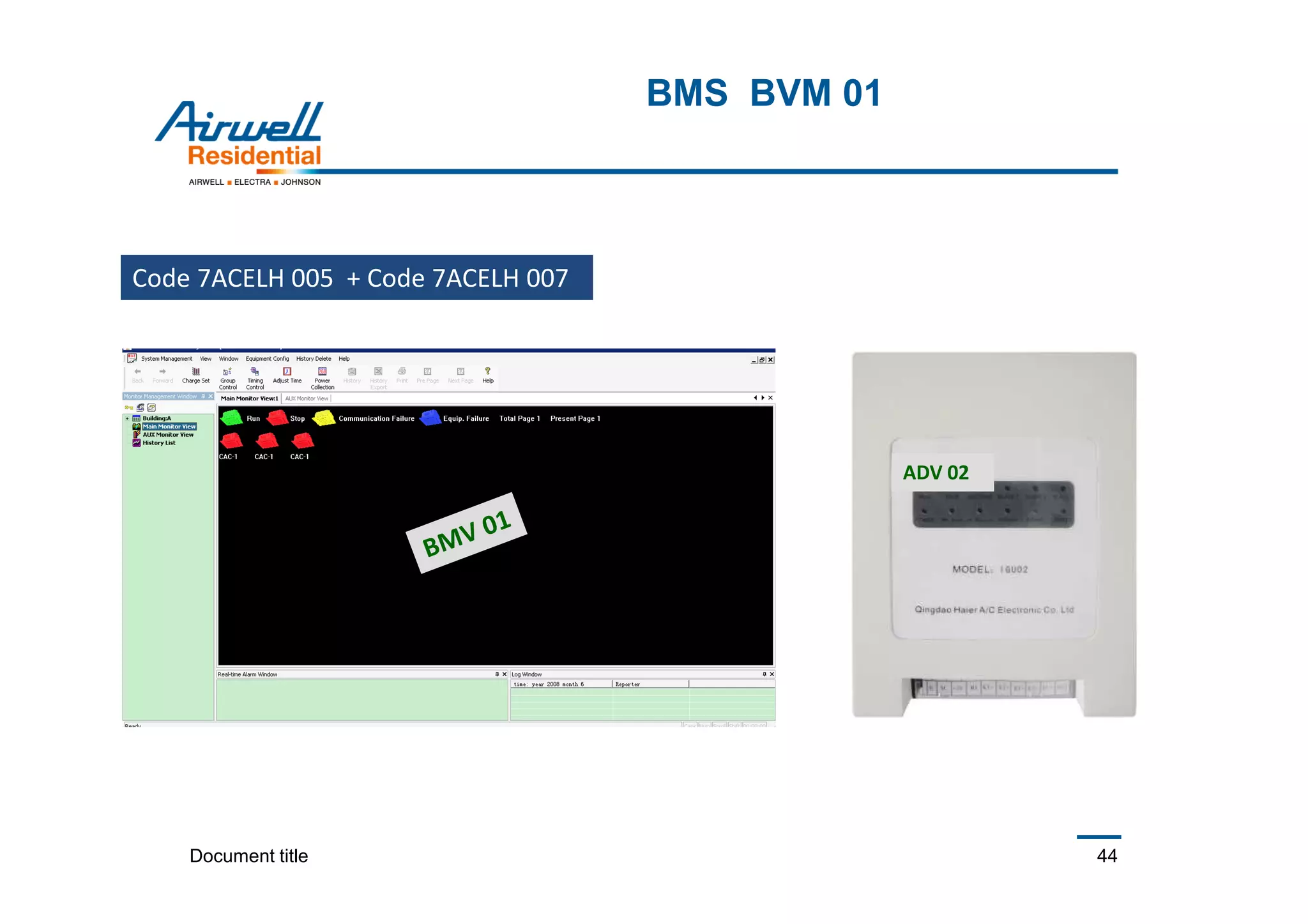
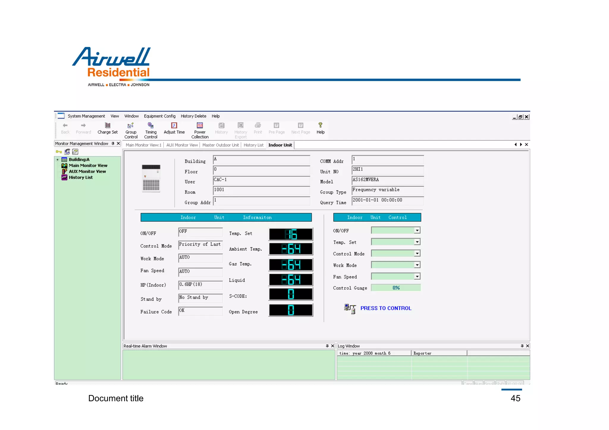
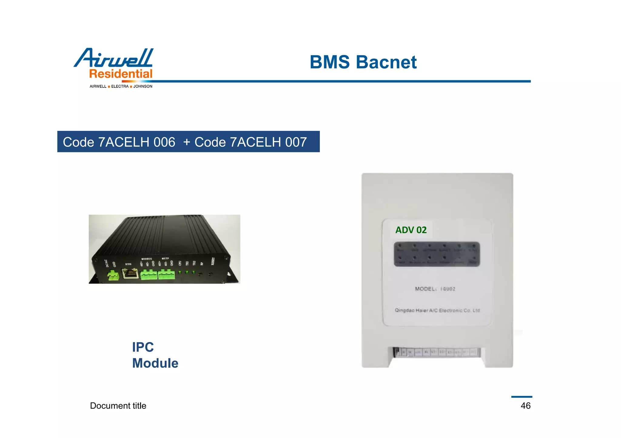
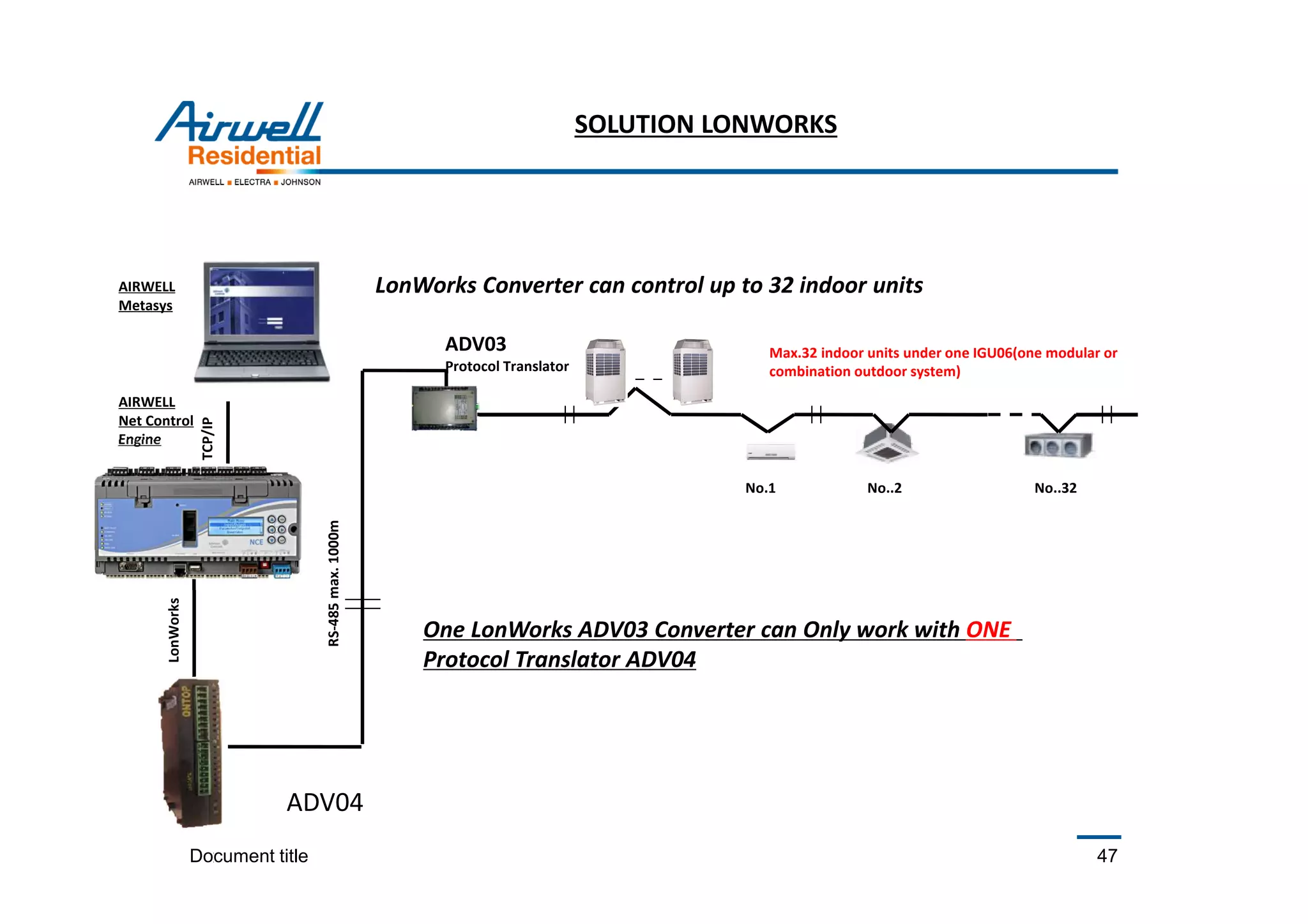
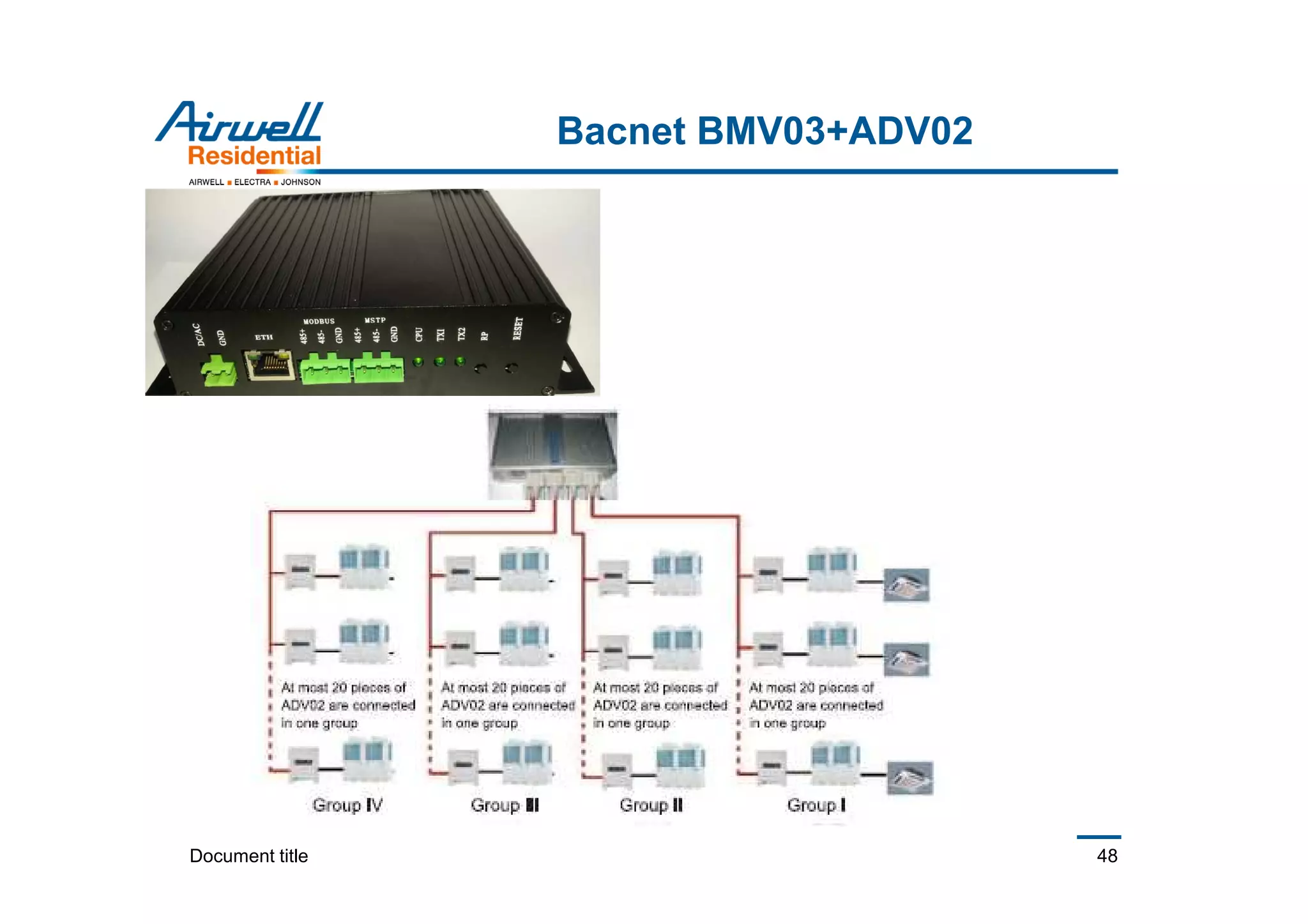
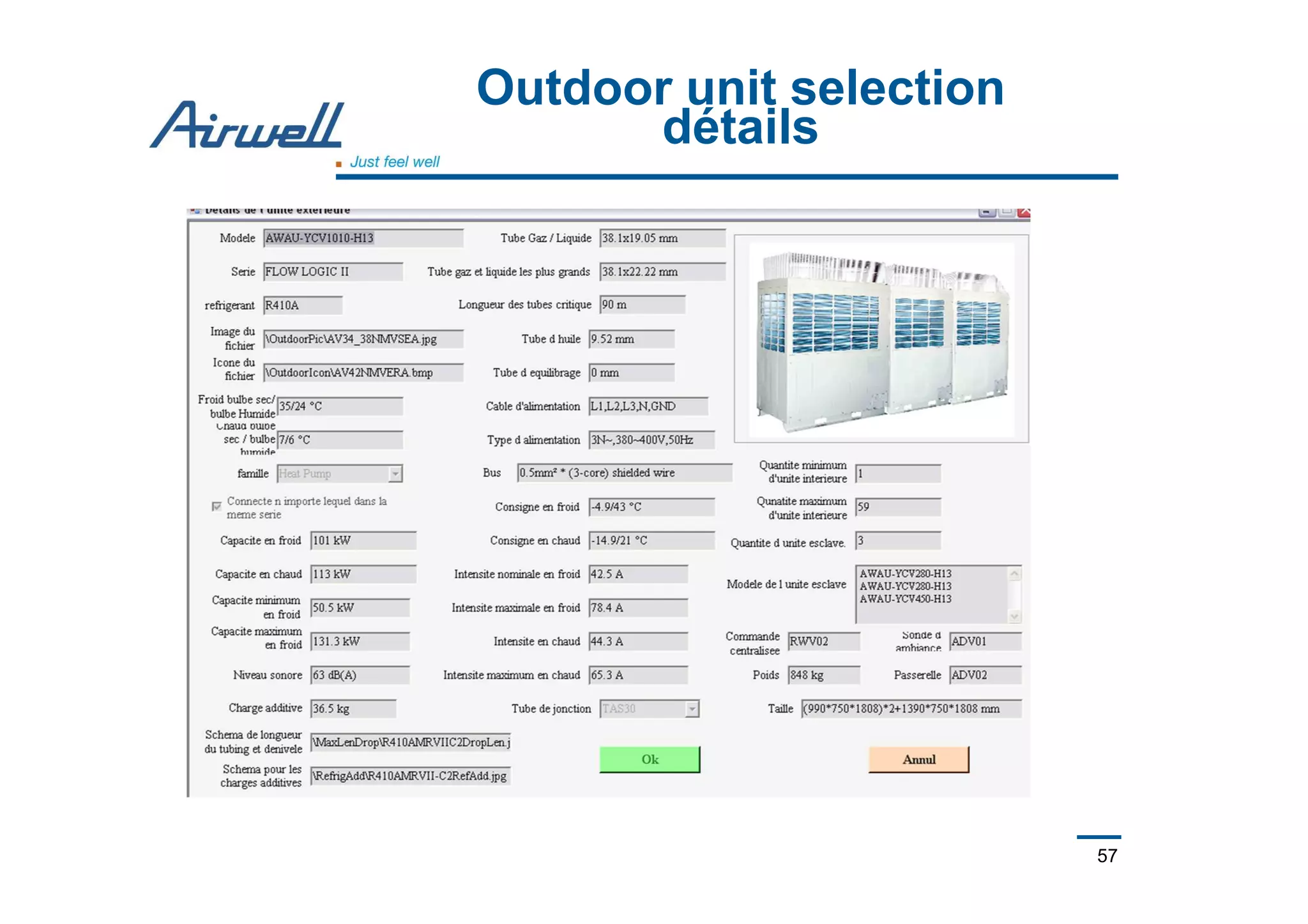
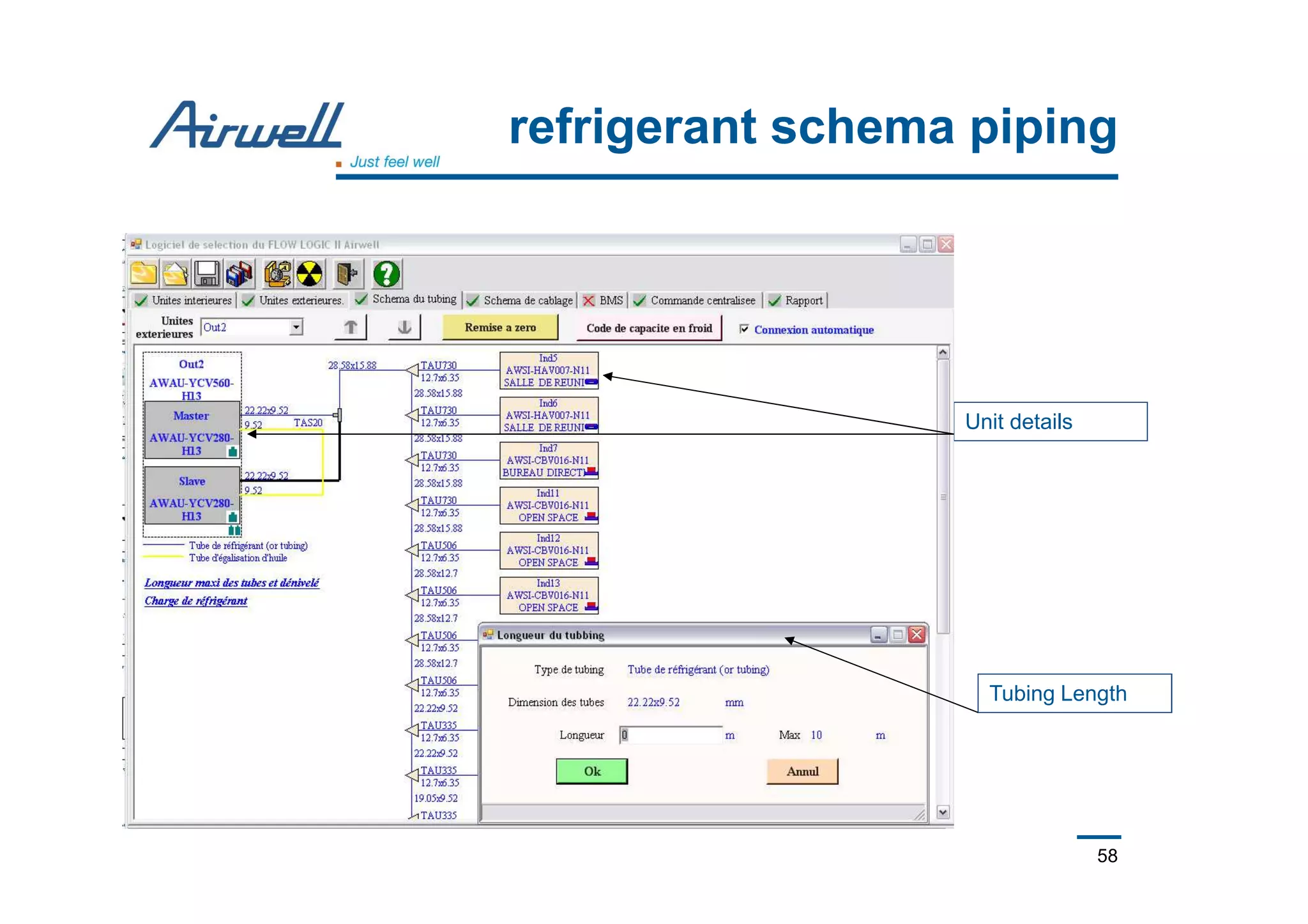
- The document discusses outdoor unit dimensions, sound levels, backup functions, installation details, controls, and building management system integration options.


![The Gift of Git [Español: La Palabra de Git]](https://cdn.slidesharecdn.com/ss_thumbnails/version-control-es-1-0-150831211616-lva1-app6891-thumbnail.jpg?width=640&height=640&fit=bounds)


![MULTI V 5 Catalogue_Small[20231107_182247769].pdf](https://cdn.slidesharecdn.com/ss_thumbnails/multiv5cataloguesmall20231107182247769-240307050612-24907867-thumbnail.jpg?width=640&height=640&fit=bounds)


![[1401-1G1311] General Catalogue](https://cdn.slidesharecdn.com/ss_thumbnails/c41b83a4-f09f-4f6c-975d-76b0386a3e0e-150708161543-lva1-app6891-thumbnail.jpg?width=640&height=640&fit=bounds)