Introduction
to Tessent
MBIST
• MBISTis a self-testing and repair mechanism which
tests the memories through an effective set of
algorithms to detect possibly all the faults that
could be present inside a typical memory cell.
• Tessent MemoryBIST also provides the ability to use
different types of repairable
memories in one controller
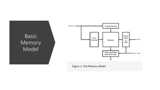
MBIST
Model
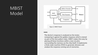
The device’s responseis analyzed on the tester,
comparing it against the golden response which is stored
as part of the test pattern data. MBIST makes this easy by
placing all these functions within a test circuitry
surrounding the memory on the chip itself. It implements
a finite state machine (FSM) to generate stimulus and
analyze the response coming out of memories.
4.
Advantage of MBIST
•Simplification of test program
• Possible to run different algorithms on memories
• Can be used for burn-in testing of memories.
• Reduction in test costs due to test time reduction and tester resources reduction
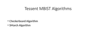
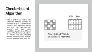
Checkerboard
Algorithm
• The 1sand 0s are written into
alternate memory locations of
the cell array in a checkerboard
pattern. The algorithm divides
the cells into two alternate
groups such that every
neighboring cell is in a different
group. The checkerboard pattern
is mainly used for activating
failures resulting from leakage,
shorts between cells, and SAF.
7.
Algorithm Steps
• Writecheckerboard with up addressing order
• Read checkerboard with up addressing order
• Write inverse checkerboard with up addressing order
• Read inverse checkerboard with up addressing order
Stuck-At Fault
In thismodel, a memory cell is permanently forced to a logic 0 (stuck-at-0
fault) or logic 1(stuck-at-1 fault) value, irrespective of any value written to
the cell. This is the most common fault, but also the easiest to detect.
Stuck-Open Faults
In this Fault memory word cannot be accessed. When the sense
amplifier contains a latch then during a read operation the
previously read value may be produced. If differential amplifier
behaves as a buffer it can be modeled as stuck at fault.
15.
Transition Faults
In thismodel, a memory cell fails to undergo a transition from a logic 0 to a logic 1
value (up transition fault) or from a logic 1 to a logic 0 value (down transition fault).
These faults are special cases of stuck-at faults because of the fact that once the non-
faulty transition occurs, the faulty cell can no longer transition and hence manifests
stuck-at behavior.
Detection Requirements:
To detect an up transition fault, the following sequence of events must occur:
1. The cell under test must be storing a logic 0.
2. A logic 1 must be written into the cell.
3. The cell must be read before a logic 0 is written to it.
To detect a down transition fault, the following sequence of events must occur:
1. The cell under test must be storing a logic 1.
2. A logic 0 must be written into the cell.
3. The cell must be read before a logic 1 is written to it
16.
Address Decoder Faults
Thismodel encompasses faults in the address decoder logic. Three different faulty
behaviors are possible:
• ADa: a certain address results in no cell being accessed.
• ADb: a certain address simultaneously accesses multiple cells.
• ADc: a certain cell can be accessed by multiple addresses.
It has been shown that the above address decoder faults can in fact be mapped to
faults in the memory cell array. Therefore covering the memory cell array faults results
in these faults also being covered.
17.
Inversion Coupling Faults
Inthis fault model, a logic 0 to logic 1 or logic 1 to logic 0 transition in one memory cell (the coupling
cell) inverts the value in another cell (the base cell). Two inversion coupling faults are therefore
possible between two cells:
• InCFa: a 0 to 1 transition in the coupling cell inverts the value in the base cell.
• InCFb: a 1 to 0 transition in the coupling cell inverts the value in the base cell.
The two coupled cells can appear anywhere in the memory array.
Idempotent Coupling Faults
In this fault model, a logic 0 to logic 1 or logic 1 to logic 0 transition in one memory cell (the
coupling cell) forces the value in another cell (the base cell) to either a logic 0 or logic 1. A total
of four idempotent coupling faults are therefore possible between two cells:
• IdCFa: a 0 to 1 transition in the coupling cell forces a 0 in the base cell.
• IdCFb: a 0 to 1 transition in the coupling cell forces a 1 in the base cell.
• IdCFc: a 1 to 0 transition in the coupling cell forces a 0 in the base cell.
• IdCFd: a 1 to 0 transition in the coupling cell forces a 1 in the base cell.
The two coupled cells can appear anywhere in the memory array.
18.
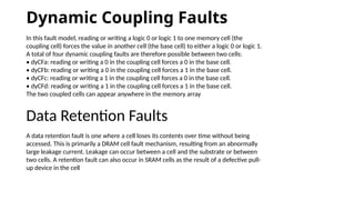
Dynamic Coupling Faults
Inthis fault model, reading or writing a logic 0 or logic 1 to one memory cell (the
coupling cell) forces the value in another cell (the base cell) to either a logic 0 or logic 1.
A total of four dynamic coupling faults are therefore possible between two cells:
• dyCFa: reading or writing a 0 in the coupling cell forces a 0 in the base cell.
• dyCFb: reading or writing a 0 in the coupling cell forces a 1 in the base cell.
• dyCFc: reading or writing a 1 in the coupling cell forces a 0 in the base cell.
• dyCFd: reading or writing a 1 in the coupling cell forces a 1 in the base cell.
The two coupled cells can appear anywhere in the memory array
Data Retention Faults
A data retention fault is one where a cell loses its contents over time without being
accessed. This is primarily a DRAM cell fault mechanism, resulting from an abnormally
large leakage current. Leakage can occur between a cell and the substrate or between
two cells. A retention fault can also occur in SRAM cells as the result of a defective pull-
up device in the cell
19.
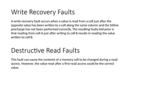
Write Recovery Faults
Awrite recovery fault occurs when a value is read from a cell just after the
opposite value has been written to a cell along the same column and the bitline
precharge has not been performed correctly. The resulting faulty behavior is
that reading from cell A just after writing to cell B results in reading the value
written to cell B.
Destructive Read Faults
This fault can cause the contents of a memory cell to be changed during a read
access. However, the value read after a first read access could be the correct
value.
20.
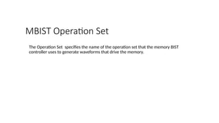
MBIST Operation Set
TheOperation Set specifies the name of the operation set that the memory BIST
controller uses to generate waveforms that drive the memory.