
Recommended
Recommended
More Related Content
Similar to Sunward hydraulic system training-SWL.ppt
Similar to Sunward hydraulic system training-SWL.ppt (9)
Recently uploaded
Recently uploaded (20)
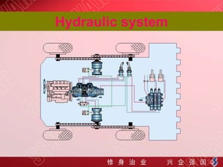
Sunward hydraulic system training-SWL.ppt
- 2. Ⅰ, Combination Pumps AA10VG + AA10VG Combination pumps make it possible to have independent circuits without the need to fit splitter gearboxes. For combination pumps consisting of more than two pumps, the mounting flange must be rated for the permissible mass torque.
- 3. Ⅰ, Variable displacement piston pump
- 4. Ⅰ, Specification of pump AA20V G 45 DG M 2 / 10 R - N T C 66 F 01 02 03 04 05 06 07 08 09 12 13 01 Axial piston unit:Variable swashplate design, nominal pressure 4350 psi (300 bar), peak pressure 5100 psi (350 bar) 02 Operation mode :Pump in closed circuit 03 Displacement :45 cm3/rev. 04 Hydraulic control :direct operated 05 Mechanical stroke limiter : With spring centering of neutral position 06 DA control valve :With DA control valve, fixed setting 07 Direction of rotation :Viewed from shaft end 08 Seals :NBR (nitrile-caoutchouc), shaft seal ring in FKM (fluor-caoutchouc) 09 Shaft end :for combination pump 10 Boost pump :with through drive
- 5. DA - Hydraulic Control, Speed Related The DA control is an engine speed-dependent, or automotive, type control system. The built-in DA regulating cartridge generates a pilot pressure that is proportional to pump (engine) drive speed. This pilot pressure is directed to the positioning cylinder of the pump by a solenoid actuated 4/3 way directional valve. Pump displacement is infinitely variable in each direction of flow, and is influenced by both pump drive speed and discharge pressure.
- 6. Main pump illustration one
- 7. Why DA control speed related? When the skid steer loader or multi terrain loader enters the pile, the wheels use more power; then, as the operator starts to lift, the hydraulics take most of the engine's power to break the bucket out of the pile. To avoid this, the machines automatically reduce the displacement of the pumps. This keeps the engine from stalling while still maintaining torque to the wheels or tracks at a reduced speed.
- 8. Main pump illustration two
- 9. Pipeline connection of main pump(Ⅰ)
- 10. Pipeline connection of main pump(Ⅱ)
- 11. Adjust the zero displacement of variable cylinder If the machine travels while hand lever is on neutral position, or if it travels in deviation when operating hand lever, check whether the variable cylinder is right on “zero” position. If not, adjust it by centering screw rod.
- 12. Adjust the zero displacement of variable cylinder
- 13. Adjust max displacement of variable cylinder When leaving factory, the oil pump’s displacement is set at 46ml/r (the max. one). If machine travels in deviation when hand lever is on the position of max.operation range, the output volume of two oil pumps is likely to be different, which can be adjusted by max. displacement limitation screw.
- 14. Travel motor-radial piston motor
- 15. Structure of motor Hydraulic motors type MCR are radial piston motors with a rotating shaft. The rotor (4) is connected to the shaft (6) by means of splines. The pistons (3) are arranged radially in the rotor (4) and are supported on the cam plate (5) by way of rollers (8).
- 16. Technical data of the motor Description Radial piston with fixed displacement Type mounting Flange mounting; face mounting Displacement 400 ml /r Normal flow: 400 ml /r Output torque 636 Nm Max. speed 2600rpm Nominal pressure 250 bar Brake hydraulic release holding brake
- 18. Instruction of main control valve Simple, compact and heavy duty designed 3 sections monoblock valves for open center hydraulic systems.: 1,Fitted with a main pressure relief valve. 2,Each spool has indipendent load check valve. 3,A wide variety of service port valves. 4,Diameter 18 mm --0.71 in interchangeable spools.
- 19. Dimension of the valve
- 20. Draft of control valve(one) The main overflow valve① of manifold valve determines system’s working pressure. The working pressure for this system is set at 210±10BAR, while the pressure for second overflow valves ②③ is set at 235±10bar. When manifold valve is used in large flow system, take away the plug ④, install a transition connector to channel hydraulic oil to large flow control block.
- 21. Draft of control valve(two)
- 22. Internal component of control valve
- 23. Working pressure testing Relief valve,which can adjust the working pressure Testing port,the working pressure should be about 210bar.
- 24. Introduction of pilot oil block(one) B A C D • A :working equipments • B : Pilot flow • C : brake • D : Pressure switch
- 25. Illustration of piloy oil block(two)
- 26. Illustration of piloy oil block(three)
- 27. Hydraulic oil flow of pilot oil block PH PV
- 28. Pipeline connection of pilot oil PS PG
- 29. DA control valve pressure control Testing port,which can test the pressure of DA control valve.The testing range of this should be between 6bar and 18 bar,from the lowest engine speed to the max.
- 30. Instruction of high flow control block Place a manometer whose measurement range is 60MPa in connector for pressure test. The pressure for this device can be set by adjusting safety valve. The pressure is set at 210bar when leaving factory.
- 31. Instruction of auto-leveling valve
- 32. Draft of auto-leveling valve working
- 33. Draft of auto-leveling valve
- 34. Outside view of working joystick
- 35. Hydraulic circuit of working joystick
- 36. Curve diagram of working joystick
- 37. Outside view of travel joystick
- 38. Hydraulic circuit of travel joystick
- 39. Curve diagram of travel joystick
- 40. Outside view of gear pump