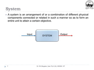
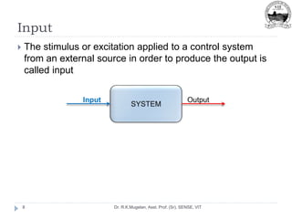
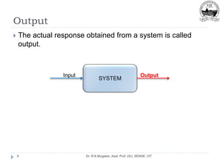
This document outlines the course ECE 2010 and provides an introduction to control systems. The course aims to give an overview of fundamental control systems concepts and applications. It will cover topics such as mathematical modeling, controller design, time and frequency domain response analysis, and state space analysis across 8 modules. References include textbooks on control systems engineering. The introduction defines key terms like systems, inputs, outputs, control, open-loop and closed-loop control systems. It also distinguishes between continuous and discrete systems, and SISO and MIMO systems. Examples of different control system types are provided.
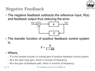
![[ECE 2010]
Dr. R.K.Mugelan, Asst. Professor (Sr), SENSE, VIT](https://image.slidesharecdn.com/module-1-220908012311-81983bb1/85/Introduction-to-Control-System-1-320.jpg)
![[ECE 2010]
Dr. R.K.Mugelan, Asst. Professor (Sr), SENSE, VIT](https://image.slidesharecdn.com/module-1-220908012311-81983bb1/75/Introduction-to-Control-System-1-2048.jpg)