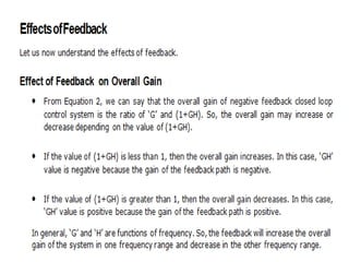
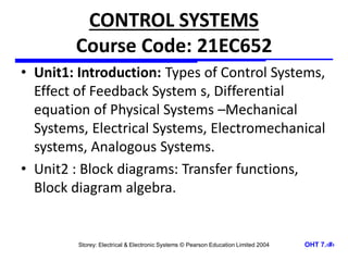
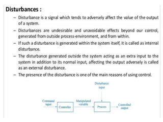
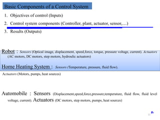
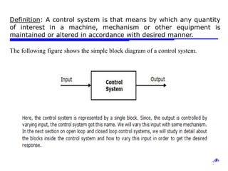
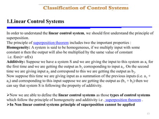
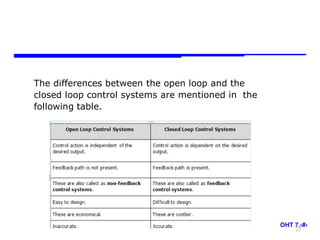
The document provides a comprehensive overview of control systems, including types, components, and classifications such as open-loop and closed-loop systems. It explains concepts like feedback, linear and nonlinear systems, and the principle of superposition. Additionally, it discusses how feedback affects system performance and includes examples of various control applications.
![Storey: Electrical & Electronic Systems © Pearson Education Limited 2004 OHT 7.‹#›
27
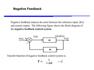
C(S)=E(S)G(S) ----1
E(S) = R(S)-H(S)C(S) ---2
Use value of E(S) into C(S)
Then C(S) =G(S)[R(S)-H(S)C(S)]
C(S) = G(S)R(S)- G(S)H(S)C(S)
C(S)+ G(S)H(S)C(S)=G(S)R(S)
C(S)[1+G(S)H(S)]= G(S)R(S)
T=C(S)/R(S)=G(S)/1+G(S)H(S)
E(S)
G(s)E(s)
C(S)H(S)](https://image.slidesharecdn.com/module1-typeseffect-240714134454-2a7160e4/85/Module1-types-effect-pdf-shsbshbsvshshshsg-27-320.jpg)