This document describes a lecture on the Intel 8086 instruction set. It discusses writing real-mode 8086 assembly language programs that include data transfer between registers and memory, arithmetic/logic instructions, conditional jumps, subroutine calls, segment/offset addressing, and interrupts. The goal is to learn enough of the 8086 instruction set to write simple routines to service interrupts and read/write I/O ports. An example program is provided to demonstrate various 8086 features.
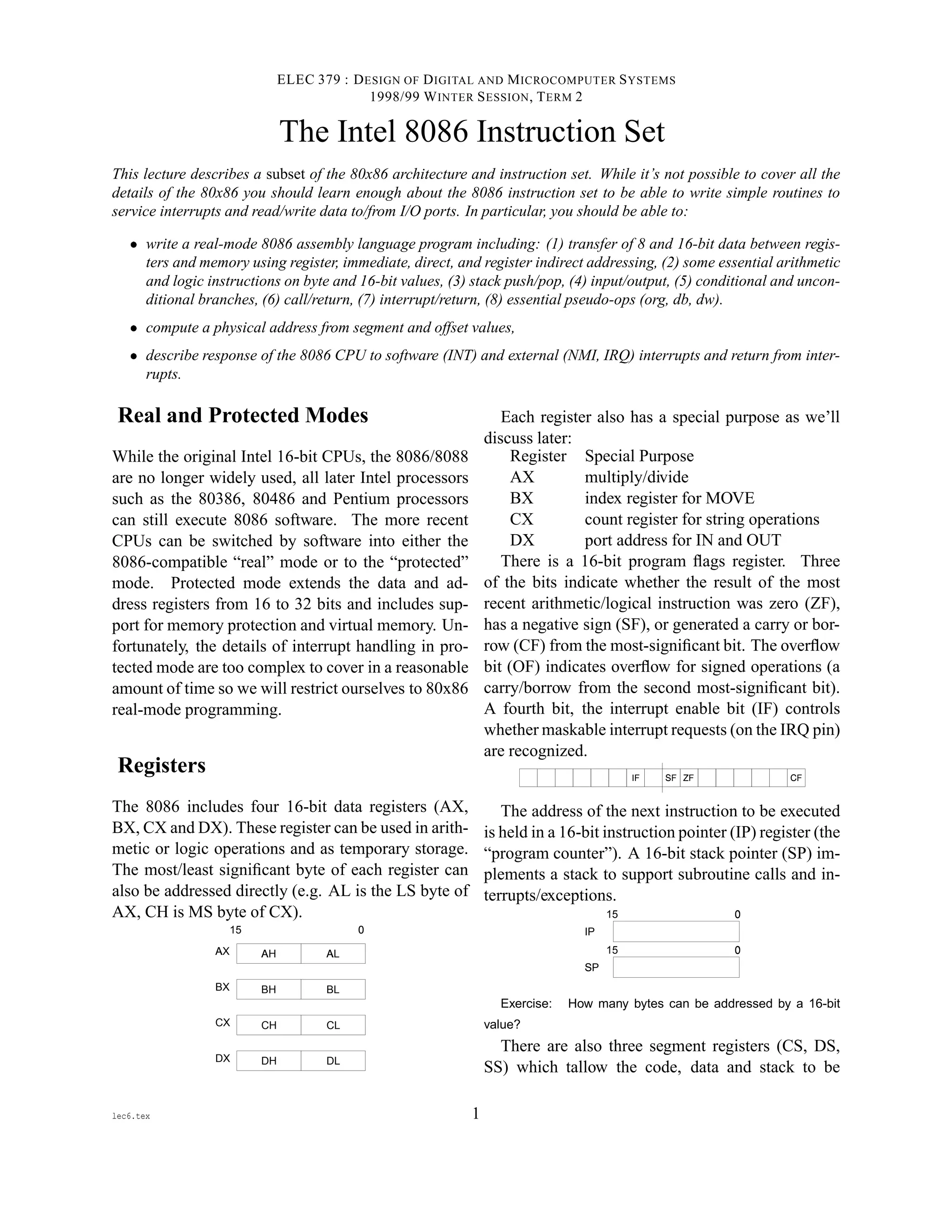
![placed in any three 64 kByte “segments” within
the CPU’s 1 megabyte (20-bit) address space as de-
scribed later.
DS
CS
SS
§
15 0
¨
Instruction Set
We only cover the small subset of the 8088 instruc-
tion set that is essential. In particular, we will not
mention various registers, addressing modes and in-
structions that could often provide faster ways of do-
ing things.
A summary of the 80x86 protected-mode instruc-
tion set is available on the course Web page and
should be printed out if you don’t have another ref-
erence.
Data Transfer
The MOV instruction is used to transfer 8 and 16-bit
data to and from registers. Either the source or des-
tination has to be a register. The other operand can
come from another register, from memory, from im-
mediate data (a value included in the instruction) or
from a memory location “pointed at” by register BX.
For example, if COUNT is the label of a memory lo-
cation the following are possible assembly-language
instructions :
; register: move contents of BX to AX
MOV AX,BX
; direct: move contents of AX to memory
MOV COUNT,AX
; immediate: load CX with the value 240
MOV CX,0F0H
; memory: load CX with the value at
; address 240
MOV CX,[0F0H]
; register indirect: move contents of AL
; to memory location in BX
MOV [BX],AL
Most 80x86 assemblers keep track of the type of
each symbol and require a type “override” when the
symbol is used in a different way. The OFFSET oper-
ator to convert a memory reference to a 16-bit value.
For example:
MOV BX,COUNT ; load the value at location COUNT
MOV BX,OFFSET COUNT ; load the offset of COUNT
16-bit registers can be pushed (the SP is first
decremented by two and then the value stored at SP)
or popped (the value is restored from the memory at
SP and then SP is incremented by 2). For example:
PUSH AX ; push contents of AX
POP BX ; restore into BX
There are some things to note about Intel assembly
language syntax:
©
the order of the operands is destination,source
— the reverse of that used on the 68000!
©
semicolons begin a comment
©
the suffix ’H’ is used to indicate a hexadecimal
constant, if the constant begins with a letter it
must be prefixed with a zero to distinguish it
from a label
©
the suffix ’B’ indicates a binary constant
©
square brackets indicate accesses to memory
©
the size of the transfer (byte or word) is deter-
mined by the size of the destination
Exercise: What is the difference between the operands [CX]
and CX? What about [1000H] and 1000H? Which of the above
can be used as the destination of a MOV instruction? Which of
the above can used as the source?
I/O Operations
The 8086 has separate I/O and memory address
spaces. Values in the I/O space are accessed with
IN and OUT instructions. The port address is loaded
into DX and the data is read/written to/from AL or
AX:
MOV DX,372H ; load DX with port address
OUT DX,AL ; output byte in AL to port
; 372 (hex)
IN AX,DX ; input word to AX
2](https://image.slidesharecdn.com/intrl8086instructionset-190311131208/85/Intrl-8086-instruction-set-2-320.jpg)
![Arithmetic/Logic
Arithmetic and logic instructions can be performed
on byte and 16-bit values. The first operand has to
be a register and the result is stored in that register.
; increment BX by 4
ADD BX,4
; subtract 1 from AL
SUB AL,1
; increment BX
INC BX
; compare (subtract and set flags
; but without storing result)
CMP AX,[MAX]
; mask in LS 4 bits of AL
AND AL,0FH
; divide AX by two
SHR AX
; set MS bit of CX
OR CX,8000H
; clear AX
XOR AX,AX
Exercise: Explain how the AND, SHR (shift right), OR and
XOR instructions achieve the results given in the comments
above.
Control Transfer
Conditional jumps transfer control to another address
depending on the values of the flags in the flag reg-
ister. Conditional jumps are restricted to a range of
-128 to +127 bytes from the next instruction while
unconditional jumps can be to any point.
; jump if last result was zero (two values equal)
JZ skip
; jump if carry set (below)
JC neg
; jump on carry not set
JNC smaller
; unconditional jump:
JMP loop
The assembly-language equivalent of an if state-
ment in a high-level language is a CoMPare opera-
tion followed by a conditional jump.
Exercise: What would be the assembly-language equivalent
of the C-language statement if ( a != 0 ) goto LOOP;?
What about if ( a < b ) return ;?
The CALL and RET instructions call and return from
subroutines. The processor pushes IP on the stack
during a CALL instruction and the contents of IP are
popped by the RET instructions. For example:
CALL readchar
...
readchar:
...
RET
Exercise: Write a sequence of a MOVE, a PUSH and a
RET instruction that has the same effect as the instruction JMP
1234H?
Segment/Offset Addressing
Since address registers and address operands are only
16 bits they can only address 64k bytes. In order to
address the 20-bit address range of the 8086, physi-
cal addresses (those that are put on the address bus)
are always formed by adding the values of one of the
segment registers to the 16-bit address to form a 20-
bit address.
The segment registers themselves only contain the
most-significant 16 bits of the 20-bit value that is
contributed by the segment registers. The least sig-
nificant four bits of the segment address are always
zero.
By default, the DS (data segment) is used for
data transfer instructions (e.g. MOV), CS (code
segment) is used with control transfer instructions
(e.g. JMP or CALL), and SS is used with the stack
pointer (e.g. PUSH or to save/restore addresses dur-
ing CALL/RET or INT instructions).
Exercise: If DS contains 0100H, what address will be written
by the instruction MOV [2000H],AL? If CX contains 1122H, SP
contains 1234H, and SS contains 2000H, what memory values
will change and what will be their values when the PUSH CX
instruction is executed?
The use of segment registers reduces the size of
pointers to 16 bits. This reduces the code size but
also restricts the addressing range of a pointer to
64k bytes. Performing address arithmetic within data
structures larger than 64k is awkward. This is the
biggest drawback of the 8086 architecture.
We will restrict ourselves to short programs where
all of the code, data and stack are placed into the
same 64k segment (i.e. CS=DS=SS).
Interrupts and Exceptions
In addition to interrupts caused by external events
(such as an IRQ signal), certain instructions such as
3](https://image.slidesharecdn.com/intrl8086instructionset-190311131208/85/Intrl-8086-instruction-set-3-320.jpg)
![a dividing by zero or the INT instruction generate
exceptions.
The 8086 reserves the lower 1024 bytes of mem-
ory for an interrupt vector table. There is one
4-byte vector for each of the 256 possible inter-
rupt/exception numbers. When an interrupt or ex-
ception occurs, the processor: (1) clears the interrupt
flag in the flags register, (2) pushes the flags register,
CS, and IP (in that order), (3) loads IP and CS (in that
order) from the appropriate interrupt vector location,
and (4) transfers control to that location.
For external interrupts (IRQ or NMI) the interrupt
number is read from the data bus during an interrupt
acknowledge bus cycle. For internal interrupts (e.g.
INT instruction) the interrupt number is determined
from the instruction.
The INT instruction allows a program to generate
any of the 256 interrupts. This “software interrupt”
is typically used to access operating system services.
Exercise: MS-DOS programs use the INT 21H instruction to
request operating system services. Where would the address of
the entry point to these DOS services be found?
The CLI and STI instructions clear/set the
interrupt-enable bit in the flags register to dis-
able/enable external interrupts.
The IRET instruction pops the IP, CS and flags reg-
ister values from the stack and thus returns control to
the instruction following the one where interrupt or
exception occurred.
Exercise: What would happen if you used RET instead of
IRET to return from an interrupt?
Pseudo-Ops
A number of assembler directives (“pseudo-ops”) are
also required to write assembly language programs.
ORG specifies the location of code or data within the
segment, DB and DW assemble bytes and words of
constant data respectively.
Example
This is a simple program that demonstrates the main
features of the 8086 instruction set. It uses the INT
operation to invoke MS-DOS to write characters to
the screen.
; Sample 8086 assembly language program. This program
; prints the printable characters in a null-terminated
; string (similar to the unix ("strings" program).
; There is only one "segment" called "code" and the
; linker can assume DS and CS will be set to the right
; values for "code". The code begins at offset 100h
; within the segment "code" (MS-DOS .COM files).
code segment public
assume cs:code,ds:code
org 100h
start:
mov bx,offset msg ; bx points to string
loop:
mov al,[bx] ; load a character into al
cmp al,0 ; see if it’s a zero
jz done ; quit if so
cmp al,32 ; see if it’s printable
jl noprt ; don’t print if not
call printc ; otherwise print it
noprt:
inc bx ; point to next character
jmp loop ; and loop back
done:
int 20h ; return to DOS
; subroutine to print the byte in al
printc:
push ax ; push ax and dx
push dx
mov dl,al ; use DOS to
mov ah,02H ; print character
int 21H
pop dx ; restore ax and dx
pop ax
ret
msg db ’This’,9,31,32,’is’,20H,’a string.’,0
; example of how to reserve memory (not used above):
buf db 128 dup (?) ; 128 uninitialized bytes
code ends
end start
The offset operand is used to tell this assembler
to use the offset of msg from the start of the code
segment.
4](https://image.slidesharecdn.com/intrl8086instructionset-190311131208/85/Intrl-8086-instruction-set-4-320.jpg)