Download to read offline
![T.Y.EII Microprocessor-III N.KAPOOR 1
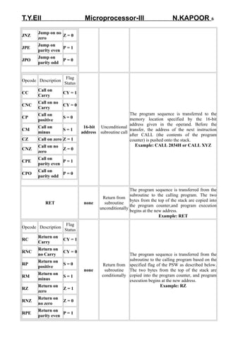
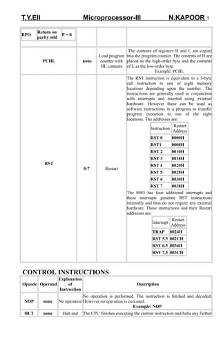
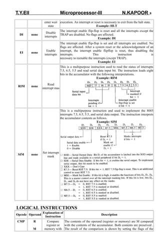
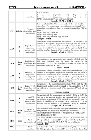
Instructions: It is a binary pattern designed inside a mp to perform specific function. The entire
group of instructions is called instruction set & determines what functions the mp can perform.
The instruction may be one , two or three byte in length. The first byte indicates the operation to
be performed & 2nd & 3rd if present contain either operand or the address of operand on which
operation has to be performed.
Instruction format : An instruction is a command to the mp to perform a given task on specified
data. In instruction the 1st byte indicates the operation to be performed &
called operation code
( opcode ). The 2nd & 3rd byte if present, contain either operand or the address of operand on
which operation is to be performed.
Instruction word size : Instruction can be One word (1-byte ) , Two word (2-byte ) or Three word
(3-byte ) .
1-Byte instruction : A one byte instruction includes the opcode & operand in the same byte.
e.g. (i) MOV C A ® 4FH ® copy the content of accumulator in register C
Opcode
ADD C ® 81 H ® add content of register C to accumulator. CMA ® 2FH , SUB B ® 90 H, INR
A ® 3C , DCR A ® 3D
2- Byte instruction :In a two byte instruction first byte specifies the opcode & second byte either
operand or address.
opcode operand/ add
e.g. MVI R,data(8),MVI B data(8) [ 06 DATA] , SUI R data(8) , ANI data(8), ORI data(8),IN
add(8)
OUT add(8)
3-Byte instruction : 1st byte specifies the . & 2nd & 3rd byte specifies 16-bit address. 2nd byte is
lower order address & 3rd byte is higher order address. e.g. LDA add(16), STA add(16), LHLD
add(16), JMP add(16)
Op-code Format : In 8085 m p all operation registers & status flags are identified with a specific
code.
code Register code Register
000 B 110 Memory related operations
001 C 111 A
010 D 00 BC
011 E 01 DE
100 H 10 HL
101 L 11 AF or SP
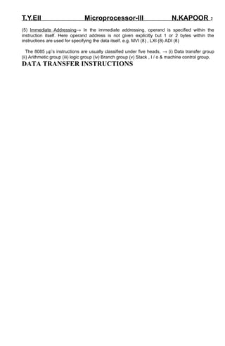
Addressing Modes® Each instruction specifies an operation to be performed on certain data.
There are different techniques by which address of the data to be operated upon may be
specified. These techniques are known as “ addressing modes”. The four modes of addressing
in 8085 are -- (1) Implied Addressing ® (Inherent addressing) In implied addressing, no
address is necessary because the location is implied in the instruction itself. e.g. (I) NOP-- No
operation. (No address is necessary) (ii) STC -- Set carry flag.
(2) Direct Addressing® In direct addressing the address of operand is explicitly specified within
the instruction itself. All such instructions are 3-byte long. e.g. LDA add (16), STA add (16).
(3) Register Addressing® When operands for any operation are in the general purpose
register, only the registers need to be specified as the address of operands. Such addressing
modes is called register addressing. These are 1 byte within that byte, operation code &
register is specified. e.g. MOV A, B, ADD B.
(4) Indirect Addressing® In this mode contents of specified registers are assumed to be
address of operand instead of being the operand itself. In this case instead of specifying
register, a register pair is specified to hold the 16-bit address of the operand. MOV A M- Move
contents of memory location, pointed by HL-pair to the accumulator. JMP add (16).](https://image.slidesharecdn.com/5nysxqqnqnyqyp51ztzn-signature-a7cc87ee7a34b721e7e1a0f6084ce632229073650e86cf377eb3bcbe94ebf6cd-poli-140927114907-phpapp01/85/Microprocessor-Basics-CH-3-1-320.jpg)
![T.Y.EII Microprocessor-III N.KAPOOR 1
Instructions: It is a binary pattern designed inside a mp to perform specific function. The entire
group of instructions is called instruction set & determines what functions the mp can perform.
The instruction may be one , two or three byte in length. The first byte indicates the operation to
be performed & 2nd & 3rd if present contain either operand or the address of operand on which
operation has to be performed.
Instruction format : An instruction is a command to the mp to perform a given task on specified
data. In instruction the 1st byte indicates the operation to be performed &
called operation code
( opcode ). The 2nd & 3rd byte if present, contain either operand or the address of operand on
which operation is to be performed.
Instruction word size : Instruction can be One word (1-byte ) , Two word (2-byte ) or Three word
(3-byte ) .
1-Byte instruction : A one byte instruction includes the opcode & operand in the same byte.
e.g. (i) MOV C A ® 4FH ® copy the content of accumulator in register C
Opcode
ADD C ® 81 H ® add content of register C to accumulator. CMA ® 2FH , SUB B ® 90 H, INR
A ® 3C , DCR A ® 3D
2- Byte instruction :In a two byte instruction first byte specifies the opcode & second byte either
operand or address.
opcode operand/ add
e.g. MVI R,data(8),MVI B data(8) [ 06 DATA] , SUI R data(8) , ANI data(8), ORI data(8),IN
add(8)
OUT add(8)
3-Byte instruction : 1st byte specifies the . & 2nd & 3rd byte specifies 16-bit address. 2nd byte is
lower order address & 3rd byte is higher order address. e.g. LDA add(16), STA add(16), LHLD
add(16), JMP add(16)
Op-code Format : In 8085 m p all operation registers & status flags are identified with a specific
code.
code Register code Register
000 B 110 Memory related operations
001 C 111 A
010 D 00 BC
011 E 01 DE
100 H 10 HL
101 L 11 AF or SP
Addressing Modes® Each instruction specifies an operation to be performed on certain data.
There are different techniques by which address of the data to be operated upon may be
specified. These techniques are known as “ addressing modes”. The four modes of addressing
in 8085 are -- (1) Implied Addressing ® (Inherent addressing) In implied addressing, no
address is necessary because the location is implied in the instruction itself. e.g. (I) NOP-- No
operation. (No address is necessary) (ii) STC -- Set carry flag.
(2) Direct Addressing® In direct addressing the address of operand is explicitly specified within
the instruction itself. All such instructions are 3-byte long. e.g. LDA add (16), STA add (16).
(3) Register Addressing® When operands for any operation are in the general purpose
register, only the registers need to be specified as the address of operands. Such addressing
modes is called register addressing. These are 1 byte within that byte, operation code &
register is specified. e.g. MOV A, B, ADD B.
(4) Indirect Addressing® In this mode contents of specified registers are assumed to be
address of operand instead of being the operand itself. In this case instead of specifying
register, a register pair is specified to hold the 16-bit address of the operand. MOV A M- Move
contents of memory location, pointed by HL-pair to the accumulator. JMP add (16).](https://image.slidesharecdn.com/5nysxqqnqnyqyp51ztzn-signature-a7cc87ee7a34b721e7e1a0f6084ce632229073650e86cf377eb3bcbe94ebf6cd-poli-140927114907-phpapp01/75/Microprocessor-Basics-CH-3-1-2048.jpg)
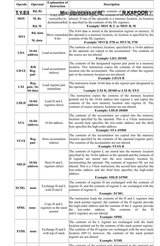
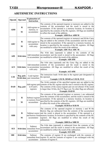
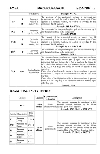

The document discusses the instruction set and addressing modes of the 8085 microprocessor. It describes the different types of instructions - 1-byte, 2-byte, and 3-byte - and how they specify the operation code and operands. It also explains the four addressing modes used by the 8085: implied, direct, register, and indirect addressing. Finally, it provides details on the various instruction groups for data transfer, arithmetic, logic, branching, and machine control operations.