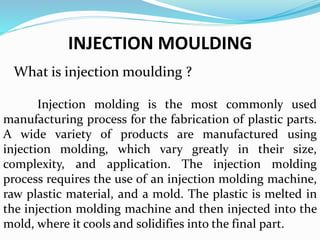
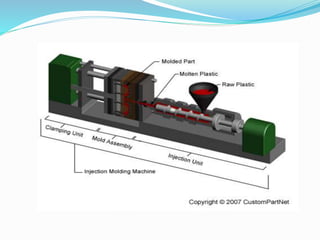
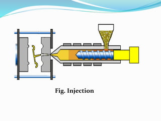
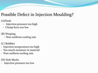
Blow Molding Process on Manufacturing Technology .
Tackles about the definition of Blow molding process, its various types , advantages and disadvantages and the application of it on a manufacturing set-up.
Blow Molding Process on Manufacturing Technology .
Tackles about the definition of Blow molding process, its various types , advantages and disadvantages and the application of it on a manufacturing set-up.
Injection moulding is a manufacturing technique for making parts from both thermoplastic and thermosetting. Plastic material in production molten plastic is injected at high pressure into a mould.
this file is useful for industrial and manufacturing & also for mechanical engineers & usefull for the industrial point of view
This file is about injection molding for plastics
best of luck
Plastics are difficult to recognize by only their appearance, same as wood or various other materials.
In this way, there are a few tests which are utilized to distinguish a portion of the plastics.
Six injection molding processing technologies for plastic products for home a...JasmineHL
The molding and processing methods of plastic products for home appliances mainly include injection molding, extrusion molding, thermoforming, hollow molding, lamination molding, compression molding, transfer molding, foam plastic molding, casting molding, insert casting, sealing casting, etc., among which Mainly injection molding.
Fabrication of Plastics in polymer technology for B.Tech students in India specially for JNTU K,H&A in Andhra Pradesh Telangana and also for other Indian Universities.
By
Gurram.Achyuth Kumar
A
Conceptual design of injection mold tool for the chair hand rest componenteSAT Publishing House
IJRET : International Journal of Research in Engineering and Technology is an international peer reviewed, online journal published by eSAT Publishing House for the enhancement of research in various disciplines of Engineering and Technology. The aim and scope of the journal is to provide an academic medium and an important reference for the advancement and dissemination of research results that support high-level learning, teaching and research in the fields of Engineering and Technology. We bring together Scientists, Academician, Field Engineers, Scholars and Students of related fields of Engineering and Technology
CFD Simulation of By-pass Flow in a HRSG module by R&R Consult.pptxR&R Consult
CFD analysis is incredibly effective at solving mysteries and improving the performance of complex systems!
Here's a great example: At a large natural gas-fired power plant, where they use waste heat to generate steam and energy, they were puzzled that their boiler wasn't producing as much steam as expected.
R&R and Tetra Engineering Group Inc. were asked to solve the issue with reduced steam production.
An inspection had shown that a significant amount of hot flue gas was bypassing the boiler tubes, where the heat was supposed to be transferred.
R&R Consult conducted a CFD analysis, which revealed that 6.3% of the flue gas was bypassing the boiler tubes without transferring heat. The analysis also showed that the flue gas was instead being directed along the sides of the boiler and between the modules that were supposed to capture the heat. This was the cause of the reduced performance.
Based on our results, Tetra Engineering installed covering plates to reduce the bypass flow. This improved the boiler's performance and increased electricity production.
It is always satisfying when we can help solve complex challenges like this. Do your systems also need a check-up or optimization? Give us a call!
Work done in cooperation with James Malloy and David Moelling from Tetra Engineering.
More examples of our work https://www.r-r-consult.dk/en/cases-en/
Overview of the fundamental roles in Hydropower generation and the components involved in wider Electrical Engineering.
This paper presents the design and construction of hydroelectric dams from the hydrologist’s survey of the valley before construction, all aspects and involved disciplines, fluid dynamics, structural engineering, generation and mains frequency regulation to the very transmission of power through the network in the United Kingdom.
Author: Robbie Edward Sayers
Collaborators and co editors: Charlie Sims and Connor Healey.
(C) 2024 Robbie E. Sayers
Hierarchical Digital Twin of a Naval Power SystemKerry Sado
A hierarchical digital twin of a Naval DC power system has been developed and experimentally verified. Similar to other state-of-the-art digital twins, this technology creates a digital replica of the physical system executed in real-time or faster, which can modify hardware controls. However, its advantage stems from distributing computational efforts by utilizing a hierarchical structure composed of lower-level digital twin blocks and a higher-level system digital twin. Each digital twin block is associated with a physical subsystem of the hardware and communicates with a singular system digital twin, which creates a system-level response. By extracting information from each level of the hierarchy, power system controls of the hardware were reconfigured autonomously. This hierarchical digital twin development offers several advantages over other digital twins, particularly in the field of naval power systems. The hierarchical structure allows for greater computational efficiency and scalability while the ability to autonomously reconfigure hardware controls offers increased flexibility and responsiveness. The hierarchical decomposition and models utilized were well aligned with the physical twin, as indicated by the maximum deviations between the developed digital twin hierarchy and the hardware.
Welcome to WIPAC Monthly the magazine brought to you by the LinkedIn Group Water Industry Process Automation & Control.
In this month's edition, along with this month's industry news to celebrate the 13 years since the group was created we have articles including
A case study of the used of Advanced Process Control at the Wastewater Treatment works at Lleida in Spain
A look back on an article on smart wastewater networks in order to see how the industry has measured up in the interim around the adoption of Digital Transformation in the Water Industry.
Immunizing Image Classifiers Against Localized Adversary Attacksgerogepatton
This paper addresses the vulnerability of deep learning models, particularly convolutional neural networks
(CNN)s, to adversarial attacks and presents a proactive training technique designed to counter them. We
introduce a novel volumization algorithm, which transforms 2D images into 3D volumetric representations.
When combined with 3D convolution and deep curriculum learning optimization (CLO), itsignificantly improves
the immunity of models against localized universal attacks by up to 40%. We evaluate our proposed approach
using contemporary CNN architectures and the modified Canadian Institute for Advanced Research (CIFAR-10
and CIFAR-100) and ImageNet Large Scale Visual Recognition Challenge (ILSVRC12) datasets, showcasing
accuracy improvements over previous techniques. The results indicate that the combination of the volumetric
input and curriculum learning holds significant promise for mitigating adversarial attacks without necessitating
adversary training.
Student information management system project report ii.pdfKamal Acharya
Our project explains about the student management. This project mainly explains the various actions related to student details. This project shows some ease in adding, editing and deleting the student details. It also provides a less time consuming process for viewing, adding, editing and deleting the marks of the students.
Saudi Arabia stands as a titan in the global energy landscape, renowned for its abundant oil and gas resources. It's the largest exporter of petroleum and holds some of the world's most significant reserves. Let's delve into the top 10 oil and gas projects shaping Saudi Arabia's energy future in 2024.
2. INJECTION MOULDING
What is injection moulding ?
Injection molding is the most commonly used
manufacturing process for the fabrication of plastic parts.
A wide variety of products are manufactured using
injection molding, which vary greatly in their size,
complexity, and application. The injection molding
process requires the use of an injection molding machine,
raw plastic material, and a mold. The plastic is melted in
the injection molding machine and then injected into the
mold, where it cools and solidifies into the final part.
3.
4. Injection molding is used to produce thin-walled plastic
parts for a wide variety of applications, one of the most
common being plastic housings. Plastic housing is a thin-
walled enclosure, often requiring many ribs and bosses on
the interior. These housings are used in a variety of
products including household appliances, consumer
electronics, power tools, and as automotive dashboards.
Other common thin-walled products include different
types of open containers, such as buckets. Injection
molding is also used to produce several everyday items
such as toothbrushes or small plastic toys. Many medical
devices, including valves and syringes, are manufactured
using injection molding as well.
5. Process Of Cycle?
A. Clamping - Prior to the injection of the material into the mold,
the two halves of the mold must first be securely closed by the
clamping unit. Each half of the mold is attached to the injection
molding machine and one half is allowed to slide. The hydraulically
powered clamping unit pushes the mold halves together and exerts
sufficient force to keep the mold securely closed while the material
is injected. The time required to close and clamp the mold is
dependent upon the machine - larger machines will require more
time. This time can be estimated from the dry cycle time of the
machine.
6.
7. B. Injection - The raw plastic material, usually in the form
of pellets, is fed into the injection molding machine, and
advanced towards the mold by the injection unit. During
this process, the material is melted by heat and pressure.
The molten plastic is then injected into the mold very
quickly and the buildup of pressure packs and holds the
material. The amount of material that is injected is
referred to as the shot. The injection time is difficult to
calculate accurately due to the complex and changing flow
of the molten plastic into the mold. However, the injection
time can be estimated by the shot volume, injection
pressure, and injection power.
9. C. Cooling - The molten plastic that is inside the mold
begins to cool as soon as it makes contact with the interior
mold surfaces. As the plastic cools, it will solidify into the
shape of the desired part. However, during cooling
some shrinkage of the part may occur. The packing of
material in the injection stage allows additional material
to flow into the mold and reduce the amount of visible
shrinkage. The mold can not be opened until the required
cooling time has elapsed. The cooling time can be
estimated from several thermodynamic properties of the
plastic and the maximum wall thickness of the part.
10. D. Ejection - After sufficient time has passed, the cooled
part may be ejected from the mold by the ejection system,
which is attached to the rear half of the mold. When the
mold is opened, a mechanism is used to push the part out
of the mold. Force must be applied to eject the part
because during cooling the part shrinks and adheres to the
mold. In order to facilitate the ejection of the part, a mold
release agent can be sprayed onto the surfaces of the mold
cavity prior to injection of the material. The time that is
required to open the mold and eject the part can be
estimated from the dry cycle time of the machine and
should include time for the part to fall free of the mold.
Once the part is ejected, the mold can be clamped shut for
the next shot to be injected.
12. Possible Defect in Injection Moulding?
(A)Flash
- Injection pressure too high
- Clamp force too low
(B) Wraping
- Non-uniform cooling rate
(C) Bubbles
- Injection temperature too high
- Too much moisture in material
- Non-uniform cooling rate
(D) Sink Marks
- Injection pressure too low