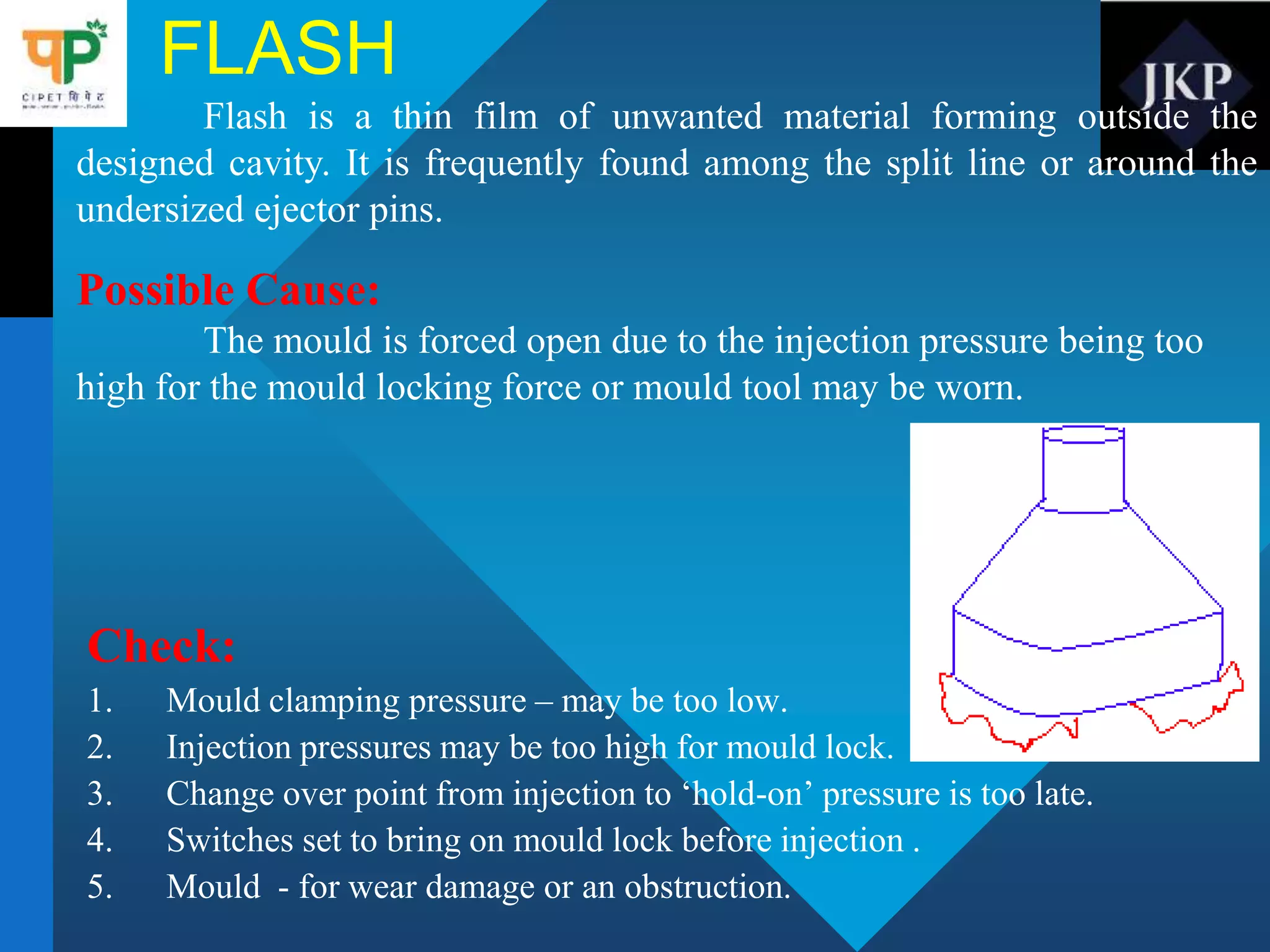
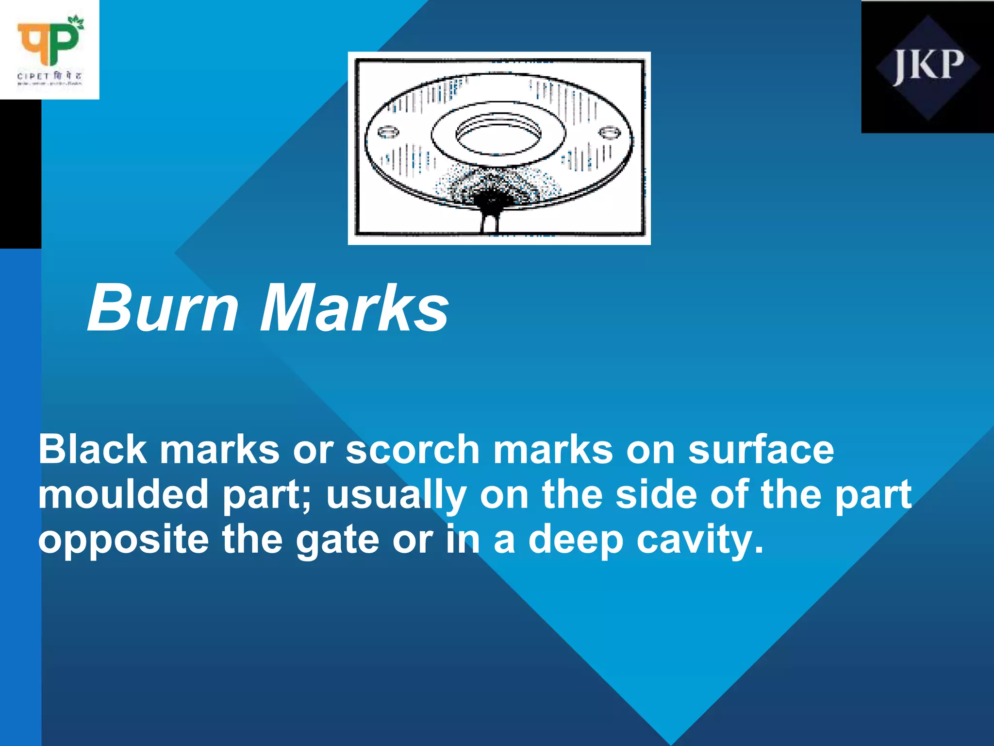
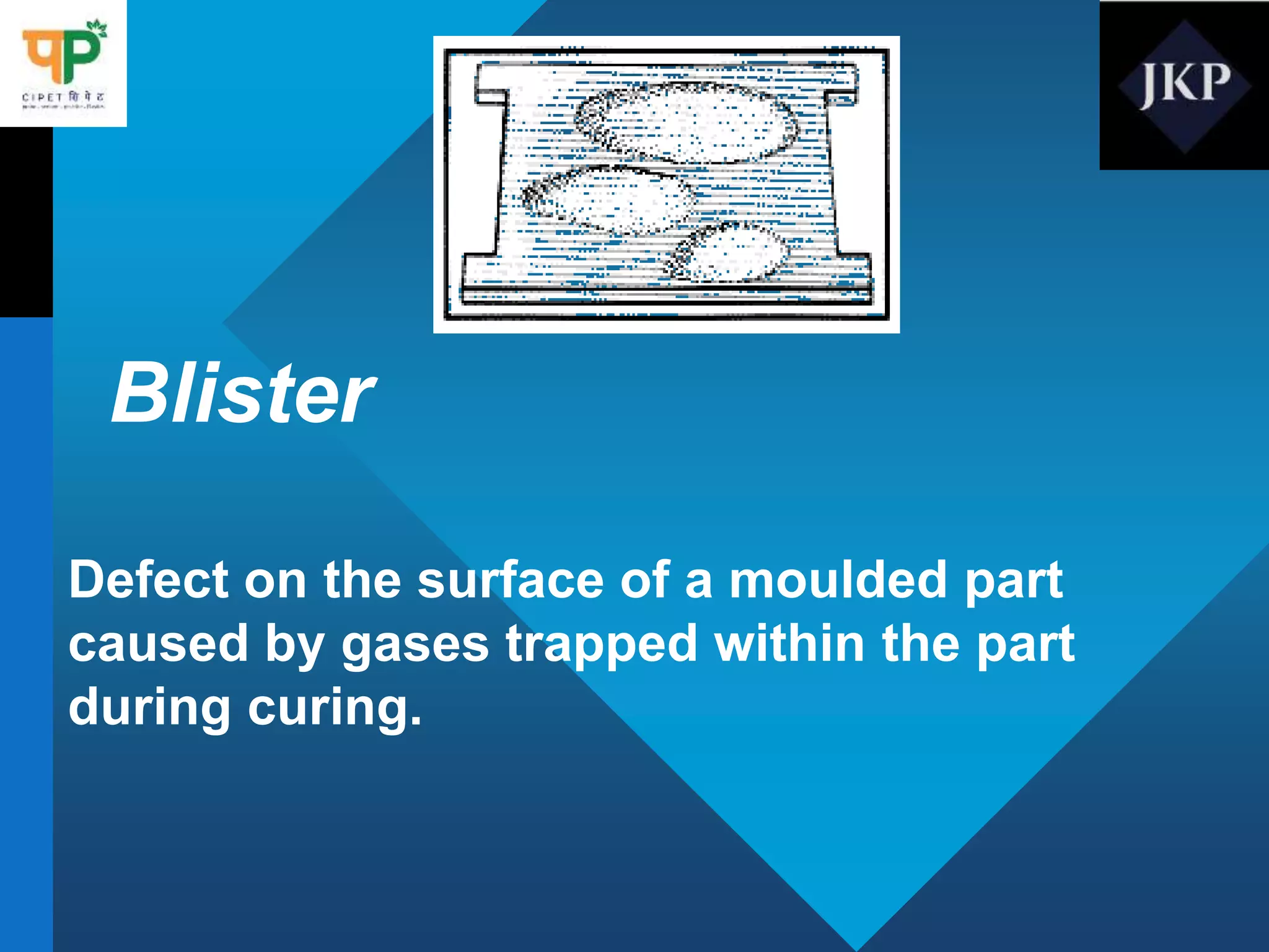
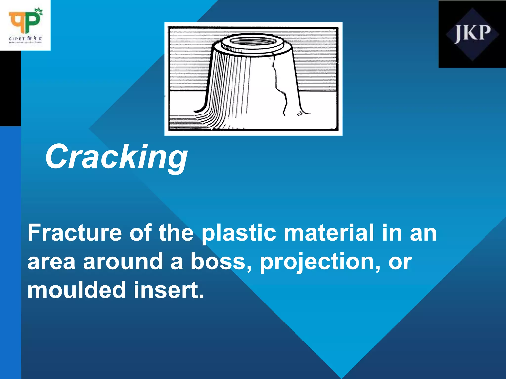
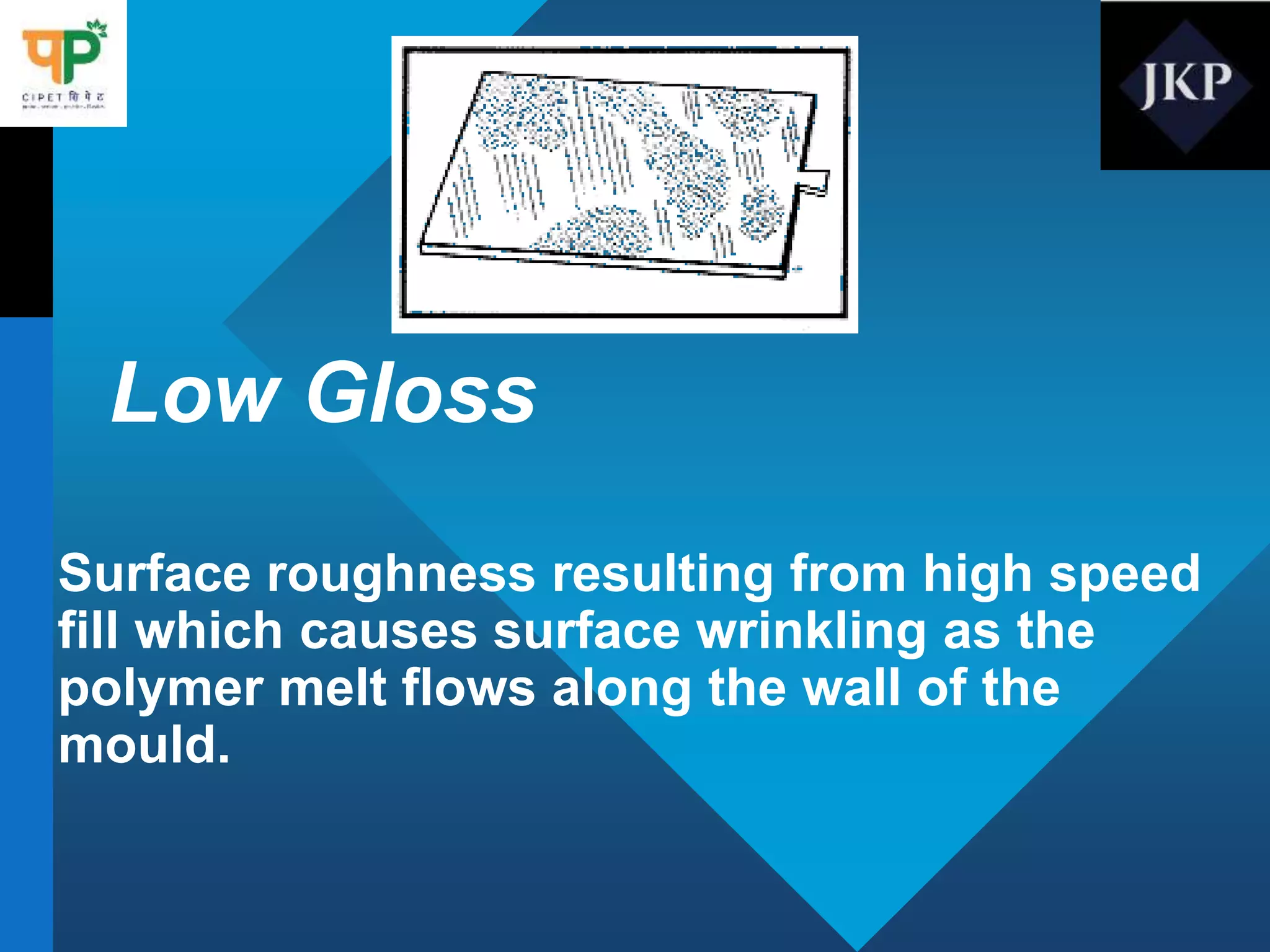
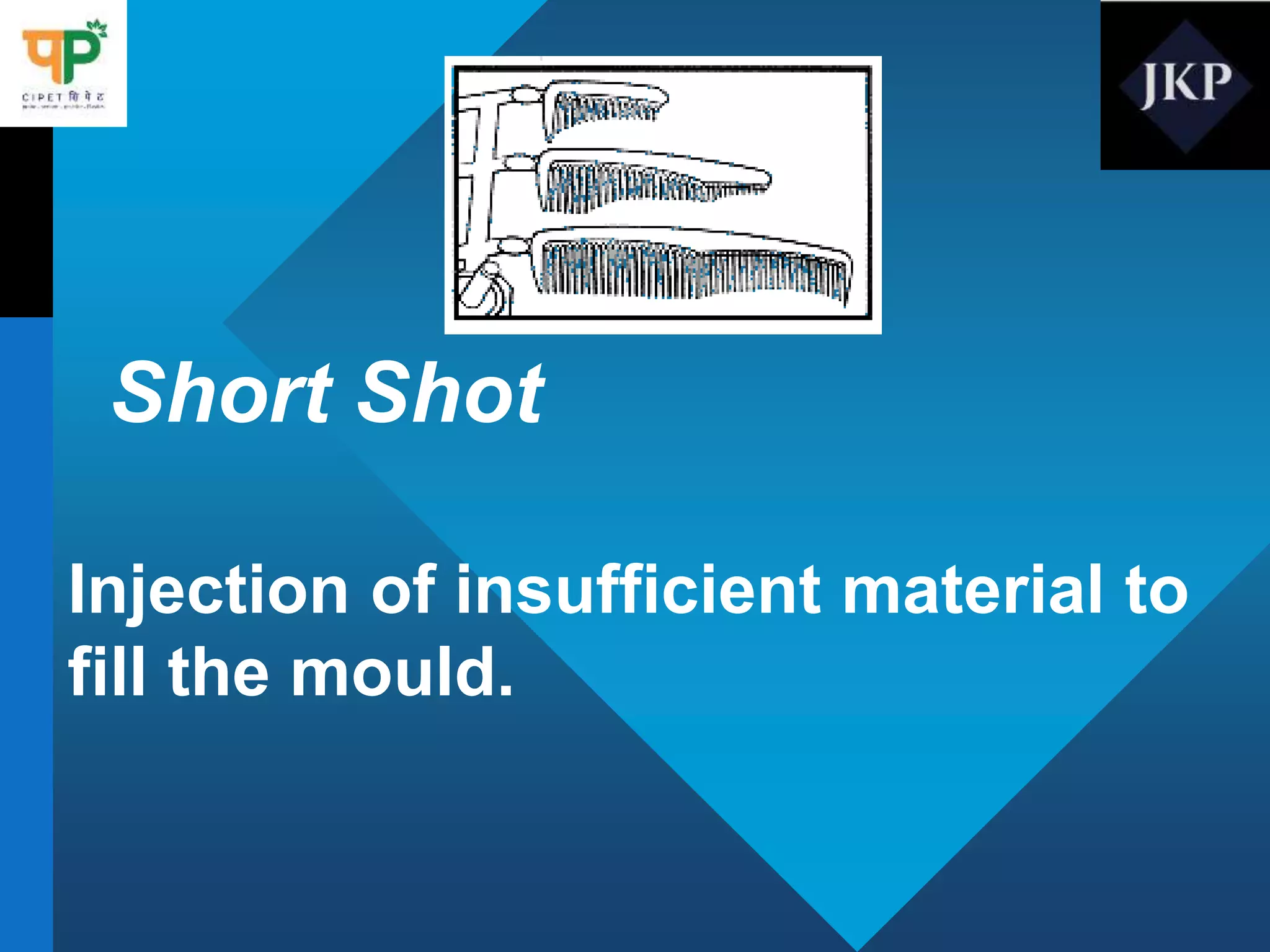
2. The Secret of effective
Trouble shooting
NEVER ADJUST ONE CONDITION TO
COMPENSATE FOR A FAILURE OR
CHANGE IN ANOTHER CONDITION.
• For example,
• If melt temp has increased, don’t reduce
speeds or pressures on mould temp to
compensate. Identify problem, that is to say
reduce melt temperature to what it was
before, by checking and replacing
thermocouples, etc.
3. Ask questions
What has changed?
What is fault?
When did it start?
How often does it occur?
Where is fault?
Is the fault randomly situated
or always in same place?
4. Identify causes of defects
Test, observe, conclude and study
“history of faults”
Injection speed : test
Screw speed : test
Back pressure : test
Melt temperature : test
Machine : check heating of cylinder
Mould temperature control
Material cushion
Locking of mould etc.
5. THE PRINCIPLE IS NOT TO CHANGE
CONDITIONS IMMEDIATELY.
Cause should be identified & rectified.
6. Short shots
A ‘short’ is an incomplete moulding. Moulding with narrow
sections or ribs are vulnerable to short shots. Frequently the moulding is
unfilled at the furthest point from the gate
Possible cause:
Insufficient Material injected into the cavity.
Check:
1. Short size
2. Injection speed – may need to be increased
3. Injection time – increase
4. Changeover point from ‘Injection’ to ‘ Holding’ pressure
5. Mould temperature - Increase
7. FLASH
Check:
1. Mould clamping pressure – may be too low.
2. Injection pressures may be too high for mould lock.
3. Change over point from injection to ‘hold-on’ pressure is too late.
4. Switches set to bring on mould lock before injection .
5. Mould - for wear damage or an obstruction.
Flash is a thin film of unwanted material forming outside the
designed cavity. It is frequently found among the split line or around the
undersized ejector pins.
Possible Cause:
The mould is forced open due to the injection pressure being too
high for the mould locking force or mould tool may be worn.
8. SINK MARKS
Check:
1. Hold – on pressure –may be too low
2. Hold – on pressure –check levels.
3. Material cushion or (pack) size.
4. Mould temperature – may need to be too low.
5. Gate – may need to be increased.
Depressions on the surface often opposite ribs, bosses or change in
section, usually worse when furthest from gate.
Possible Cause:
Material shrinkage or flowing back through the gate.
9. Burn Marks
Description
Burn Marks show up on the finish molded parts as charred or dark plastic
caused by trapped gas and is usually accompanied by a distinctive
burnt smell.
Note: If this problem is allowed to continue without fixing the root cause
it will very quickly cause damage to the molding surface.
10. Possible Solutions
-Alter gate position and/or increase gate size.
-Check for heater malfunction.
-Decrease booster time.
-Decrease injection pressure.
-Decrease injection speed.
-Decrease melt and/or mold temperature.
-Improve mold cavity venting. Vents may become smaller over time due to wear
and they will need to be brought back to their original depth.
-Reduce clamp force to improve venting. Vents may become smaller because they
are being crushed by the clamping force. If it is possible to reduce the clamping
force without causing flash then this should be done. Note: This is always good
practice to minimize wear on the mold and machine.
-Improve venting at the burn location. Burn marks often occur on deep ribs that
have no venting.
- If possible it may be helpful to put an ejector pin or sleeve at the burnt area to
allow the trapped gas to escape to atmosphere.
11. Brittleness
Description
Brittleness is a condition where the part cracks or breaks at a
much lower stress level than would normally be expected
based on the virgin material properties.
Possible Solutions
1.Check for material contamination.
2.Decrease amount of regrind use.
3.Decrease back pressure.
4.Decrease injection pressure.
5.Decrease screw speed.
6.Decrease melt temperature.
7.Dry material. Refer to the drying instructions provided by the
material supplier.
12. DISTORTION
Moulding is misshapen on ejection.
Possible cause:
Moulding is ejected from the mould before properly
solidified.
Check:
1. Cooling time – may be too short.
2. Mould temperature – may be too high.
3. Material temperature – may be too high.
4. Mould ejector system – uneven or forced ejection.
13. Bubbles
Description
Bubbles are similar to blisters in that there is air
entrapped in the molded part.
1. Possible Solutions
2. -Decrease injection speed.
-Decrease injection temperature.
-Dry material further.
-Increase injection pressure.
-Increase number and/or size of vents.
-Increase shot size.
14. JETTING:
A worm shaped area opposite and away from a gate
with flow or weld lines at the furthest edges.
POSSIBLE CAUSE:
Material enters the cavity too fast. This produces a ‘worm’ that
travels across the cavity and ‘corrugates’ to produce a back filling, the
material then radiates from the gate but does not fuse with the worm, which
is now too cold
CHECK:
1. Injection Speed – this may be too high
2. The gate – may need to alter or change its position
15. Cracking, Crazing
Description
Cracking or Crazing is caused by high internal molded in stress or by
an external force imposed upon the part. They can also be caused by an
incompatible external chemical being applied to the finished parts The cracks
often don't appear until days or weeks after the parts have been molded.
Possible Solutions
-Decrease injection pressure.
-Dry material.
-Increase cylinder temperature.
-Increase mold temperature.
-Increase nozzle temperature.
-Modify injection speed.
-If the material is partially crystalline then it may help to reduce the mold
and/or melt temperature.
-If the material is amorphous then it may help to increase the mold and/or melt
temperature.
16. Delamination
Description
Delamination occurs when single surface layers start flaking off
Possible Solutions
-Adjust injection speed.
-Check for material contamination. Incompatible resins or colorants may
have been accidentally mixed causing this condition to be seen.
-Dry material.
-Increase melt temperature.
-Increase mold temperature.
-Insufficient Blending. Check melt homogeneity and plasticizing performance
17. Discoloration
Description
Discoloration is similar to burn marks or brown streaks but
generally not as dark or severe. It may cause the part to be a darker
shade than the virgin pellets and is often found nearest the gate area,
however it can also appear as dark streaks throughout the part.
Possible Solutions
-Check hopper and feed zone for contamination.
-Decrease back pressure.
-Decrease melt temperature.
-Decrease nozzle temperature.
-Move mold to smaller shot-size press.
-Provide additional vents in mold.
-Purge heating cylinder.
-Shorten overall cycle.
18. Flow, Halo, Blush Marks
Description
Flow, Halo, Blush Marks are marks seen on the part due to
flow of the molten plastic across the molding surface.
Possible Solutions
-Decrease injection speed.
-Increase cold slug area in size or number.
-Increase injection pressure.
-Increase melt temperature.
-Increase mold temperature.
-Increase nozzle temperature.
-Increase size of sprue/runner/gate.
19. Voids
Description
Voids are hollows created in the part. They are normally found in thick
sectioned parts caused by material being pulled away from the hot center section
towards cold mold walls leaving a void in the center.
Possible Solutions
-Clean vents.
-Decrease injection speed.
-Decrease melt temperature.
-Dry material.
-Increase injection pressure.
-Increase injection-hold.
-Increase mold temperature.
-Increase shot length.
-Increase size of gate.
-Increase size of sprue and/or runners and/or gates.
20. Warping, Part Distortion
Description
Warping, Part Distortion is shows up as parts being bowed, warped, bent
or twisted beyond the normal specification outlined on the drawing.
Possible Solutions
-Adjust melt Temperature (increase to relieve molded-in stress, decrease to avoid
overpacking). stress, decrease to avoid over packing). stress, decrease
to avoid over packing).
-Check gates for proper location and adequate size.
-Check mold knockout mechanism for proper design and operation.
-Equalize/balance mold temperature of both halves.
-Increase injection-hold.
-Increase mold cooling time.
-Relocate gates on or as near as possible to thick sections.
-Try increasing or decreasing injection pressure.
21. WINDOWS (FISH EYES)
Possible Cause
Unplasticised (Unmelted) particles.
Check:
1. Barrel temperature – may have to increase.
2. Cycle time – may have to increase
3. Screw speed – may be too high
4. Back pressure – may have to increase.
Transparent sections in random places sometimes the shape and
size of granules in the direction of flow. They also occur as natural
particles when a dry coloured moulding is cut.
22. Sprue Sticking
Description
Sprue Sticking generally occurs in a cold runner mold when the sprue is
staying in the mold.
Possible Solutions
-Check mold for undercuts and/or insufficient draft.
-Decrease booster time.
-Decrease injection pressure.
-Decrease injection speed.
-Decrease injection-hold.
-Decrease mold close time.
-Decrease nozzle temperature.
-Increase core temperature.
-Open the gates.
-Ensure that the correct design of nozzle tip for the material is being used.
23. POOR SURFACE FINISH
This ranges from dull patches on a shiny finish to scratches, pit
marks and a rough finish.
Possible cause:
Implementation on mould surface or inability of melt to replicate
the mould contours.
Check:
1. Tool – polish, damage or rust marks.
2. Injection speed – may be too low
3. Mould temperature – may need to be increased
4. Injection pressure – cavity may be under – pressurised.
5. Melt temperature – may need to increase.
24. CONTAMINATION
Check:
1. Material in hopper for contamination
2. Hopper magnet for ferrous metals.
3. Raw materials form manufacturers.
4. Melt temperature – may be high
5. Screw tip, screw and nozzle for evidence of ‘Dead Spots’
due to local overheating.
Foreign material has contaminated the melt, either in the form of
bubbles, crackers, marks, marks or lumps.
Possible cause
If raw material bins or hoppers have been left uncovered it is
possible for foreign particles to enter the melt. This can also cause damage
to the mould and the screw.
25. Splash marks
Check:
1. Material – that drying requirements have been met the moisture
content of material in the hopper.
2. Melt temperature may be too high.
3. Decompression setting – may be drawing hot air in from the nozzle.
Sometimes called ‘Scuffing’ or ‘Mica Marks’. These areas or
marks on the surface of the mouldings, like silver streaks, in the
direction of flow.
Possible Cause:
They are usually caused by collapsed bubbles in the melt which have
resulted from unescaped moisture, but can also be caused by overheating the melt.
Most frequently found in hygroscopic materials such as Nylon, ABS, Acrylics, etc.
26. Flow marks
Marks at or near the surface in the form of streaks in the direction
of filling.
Possible cause:
Vague boundary lines between varying viscosities of material.
Check:
1. Injection speed –may need to be increased.
2. Melt temperature – may need to be increased.
3. Mould temperature – may need to be increased.
4. Gate – type and position may need to be changed.
27. WELD LINE
Check:
1. Injection speed too low.
2. Mould temperature – may be too low.
3. Mould vents – may be blocked.
4. Hold –on pressure may be too low.
5. Shot volume – may be too small.
6. Barrel temperature – may be too low.
A surface mark, often a line where cold fronts of material meet
eg: After flowing round a core pin, or along thicker sections.
Possible Cause:
Lack of fusion between cold fronts of material
28. IMPORTANCE OF FEED THROAT
TEMPERATURE
CASE STUDY
1. POM material barrel entry temperature- 25 C
Plasticisation temperature-210C
Resultant temperature difference -185C
If barrel entry temperature is 80 C then the difference becomes 130C,
this shows that screw has to generate more energy in the first case and lesser in the
second case. Also variation in the material intake temperature leads to inconsistent
melt quality.
2. If the throat temperature is too low, cold granules may slip over the surface of the
barrel, hence reduces the output. If too high temperature melting in the feed zone
may slip and worst case may cause bridging across the throat.
3. Too low temperature may also lead to condensing of hot volatilize on the surface of
the granules. this may show up as imperfection on the surface of the molding in
the form of blisters and streaks.
29. FEED THROAT TEMPERATURE FOR
DIFFERENT MATERIALS
MATERIAL DEG C MATERIAL DEG C
ABS 50-60 PC/PBT 80-90
ASA 50-60 PEEK 80-95
CA 40-60 PEI 80-90
CAB 40-60 PET 70-80
EVA 60-70 PES 80-90
GPPS 40-60 PMMA 50-60
HDPE 60-80 POM(co, homo) 60-70
HIPS 40-60 PP 60-80
LDPE 60-80 PP / EPDM 60-70
PA6 70-90 PPO(m) 70-80
PA66 70-90 PPS 70-80
PBT 60-70 PVC 40-60
PC 80-90 PSU 80-90
PC/ABS 70-80 SAN 50-60
30. Sink Marks
Depression in a moulded part caused by
shrinking or collapsing of the resin
during cooling.
31. Sink Marks - Problems
• Resin feed inadequate
• Improper mould design.
• Parts cool too rapidly
• Rib section in part too wide.
• Temperature of mould
surface opposite rib too hot.
• Entrapped gas.
• Nozzle too restrictive,
• land length too long.
• Pressure too low.
• Mould temperature too low or
high
• Stock temperature too high
• Gate too small
• Improper gate location
• Nozzle and metering zone
temperatures too high.
• Excessive cooling time in
mould
• Unbalanced flow pattern.
• Bad check valve.
32. Jetting
Turbulence in the resin melt flow caused by
undersized gate, abrupt change in cavity
volume, or too high injection pressure.
33. Jetting - Problems
• Excessive injection speed.
• Melt temperature too high.
• Melt temperature too low.
• mould Temperature too low.
• Nozzle opening too small.
• Gate and length too long.
• Sprue, runner, and/or gate size too small.
• Nozzle heating band malfunction.
• Inefficient gate location.
34. Splay Marks (Silver
Streaking, Splash Marks)
Marks or droplet type imperfections
formed on the surface of a finished part.
35. Splay Marks (Silver Streaking,
Splash Marks) - Problems
• Obstruction in nozzle.
• Screw rpm too high.
• Back pressure too low.
• Melt temperature too high.
• Nozzle too hot.
• Nozzle too small.
• Gates too small.
• Sprue too small.
• Insufficient venting.
• Burr in runner or gate.
• Cracked mould.
• Trapped volatiles.
• Excessive moisture.
• Resin contaminated.
• mould cavity
contamination.
• Excessive shot size.
37. Blush - Problems
• mould temperature too cold
• Injection fill speed too fast
• Melt stock temperature too high or too low.
• Improper gate location
• Sprue and nozzle diameter too small.
• Nozzle temperature too low.
• Insufficient cold slug well.
• Sharp Corners in gate area
• Resin excessively moist.
• Inadequate injection pressure.
38. Burn Marks
Black marks or scorch marks on surface
moulded part; usually on the side of the part
opposite the gate or in a deep cavity.
39. Burn Marks - Problems
• Excessive Injection speed
• Excessive injection pressure.
• Inefficient mould temperature.
• Excessive amount of volatiles
due to improper Venting.
• Improper gate location
• Front zone temperature too
high.
• Screw speed too high.
• Excessive back pressure.
• Compression ratio of screw too
high.
• Faulty temperature
controllers.
• Frictional burring--gates too
small
• Dead material hung up on
screw or nozzle.
• Melt stock temperature too
high or too low.
• Nozzle diameter too small
• Over-heated heater band
• Incorrect screw rpm.
40. Poor Weld Lines (Knit Lines)
Inability of two melt fronts to knit together in
a homogeneous fashion during the moulding
process, resulting in weak areas in the part of
varying severity.
41. Poor Weld Lines - Problems
• Material too cold.
• Injection speed too slow
• Entrapment of air at weld line.
• Improper mould design.
• Contamination of poorly
dispersed pigments.
• Core shifting.
• mould temperature to low.
• Injection speed too slow.
• Melt stock temperature to low.
• Injection pressure too low.
• Insufficient mould venting
• Cylinder temperature too low.
• Injection back pressure too
low.
• Nozzle diameter too small.
• Excessive screw flights in
metering zone.
• Improper gate locations
and/or size.
• Distance from gate
excessive.
• Ineffective flow pattern.
• mould release agent (brittle
weld lines).
• Inadequate flow.
43. Voids - Problems
• Injection pressure too low
• Packing time too short
• Insufficient feed of material
• mould temperature too low.
• Injection speed too high
• Excessive cushion
• At the side of a rib; rib too thick.
• Runners or gate too small or badly
positioned.
44. Delamination (Skinning)
Surface of the finished part separates or
appears to be composed of layer of solidified
resin. Strata or fish scale type appearance
where the layers may be separated.
45. Delamination - Problems
• Contamination of resin by additives or other
foreign materials.
• Resin temperature too low.
• Non-uniformity of resin temperature.
• Wrong mould temperature.
• Excessive material moisture.
• Inadequate injection speed.
• Sharp corners at gate.
• Incompatible polymers.
46. Flow Lines and Folds
Mark visible on the finished item that indicate
the direction of flow in the cavity.
47. Flow Lines and Folds - Problems
• Stock temperature too low.
• Runners too small
• Improper gate size and/or location.
• mould temperature too low.
• Inadequate cold slug well.
49. Warpage / Shrinkage -Problems
• mould closed time too short.
• Inefficient injection forward
time.
• Ram speed too high or too
low.
• Injection and holding
pressure too high or low.
• Melt temperature inadequate.
• Excessive nozzle and
metering zone temperatures.
• mould temperature too high
(for thick wall sections).
• Parts cool unevenly.
• Parts underpacked.
• Improper gate location.
• Gate too restrictive
• Unequal temperature
between mould halves.
• Non-uniform part ejection.
• Parts mishandled after
ejection.
• Unbalanced gates on
multiple gated part.
• Too many stresses in part.
51. Black Specks - Problems
• Contamination of material.
• Holdup of molten resin moulding machine or mould
runner system.
• Press Contamination.
• Local over-heating in the injection cylinder.
• Defective closure of the nozzle.
• Oxidation by occluded air or inadequate air venting
• mould contains grease.
• Trapped air
• Inefficient injection speed.
52. Brittleness
Tendency of a moulded part to break, crack,
shatter, etc. under conditions which it would
not normally do so.
53. Brittleness - Problems
• mould temperature too high
• Inadequate cooling in gate area
• Gate section of item too thin (gate brittleness)
• Resin too cold.
• Non-uniformity of resin temperature.
• Undried material.
• Contamination.
• Poor part design.
• Material degraded.
• Non-compatible mould release.
• Packing the mould.
• Melt temperature too cold.
• Excessive amounts of regrind.
54. Brittleness - Problems
• Inadequate mould temperature
• Excessive screw rpm
• Excessive back pressure
• Insufficient venting.
• Improper gate location.
• Excessive injection speed.
• Excessive residence timed
• Melt temperature too high.
• Nozzle too hot.
• Injection pressure too low (weld lines).
• Runners and gates in adequate (weld lines).
• Dwell time in the injection cylinder too long (material degraded).
• Material degraded during drying or pre-heating
56. Flash - Problems
• mould parting surfaces do not seal properly.
• Injection pressure too high.
• Clamp pressure set too low or projected area or item
too large for clamp pressure of the machine.
• Injection temperature too high.
• Feed needs adjustment.
• Hold time too long.
• Inadequate mould supports.
• Oversize vents.
57. Blister
Defect on the surface of a moulded part
caused by gases trapped within the part
during curing.
58. Blister - Problems
• Screw rpm too high
• Back pressure too low
• mould temperature too low.
• Gate improperly located
• Insufficient venting.
• Regrind too coarse
59. Crazing
Fine cracks in part surface. May extend
in a network over the surface or
through the part.
60. Crazing - Problems
• Insufficient drying of the material.
• Contamination.
• Injection temperature too high (crazing
accompanied by dis-coloring or yellowing).
• mould surface contaminated
• Inadequate injection speed.
• Inefficient injection forward time.
• Excessive injection pressure.
• mould temperature too low.
• Gate too large.
61. Cracking
Fracture of the plastic material in an
area around a boss, projection, or
moulded insert.
62. Cracking - Problems
• Parts cool too quickly
• moulded-in stress
• Wall thickness too heavy for compound.
63. Low Gloss
Surface roughness resulting from high speed
fill which causes surface wrinkling as the
polymer melt flows along the wall of the
mould.
64. Low Gloss - Problems
• Inadequate polish of mould surface.
• Material or mould too cold.
• Air entrapment.
• Melt index of material too low.
• Improper mould design.
• Wrong injection pressure.
• Excessive injection speed.