Downloaded 26 times


![International Journal of Computer Applications (0975 – 8887)
Volume 62– No.6, January 2013
24
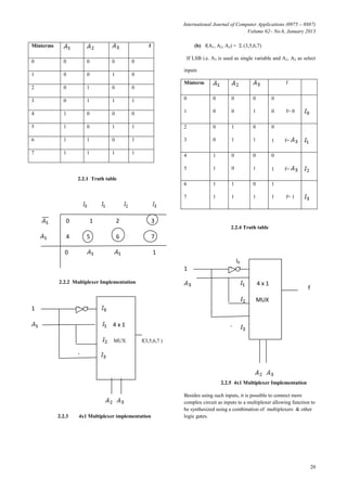
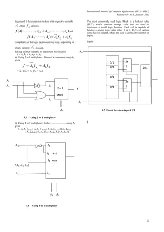
Decomposition of the function using A2, instead of A1, gives
f= Ā2fA2+A2fA2
= Ā2(A3+A1Ā4)+A2(Ā1Ā3+Ā3A4)
as fĀ2 = fA2, hence only two 3 LUTs are needed .
3.10 Using two 3 LUTs.
4. CONCLUSION
In this paper we have seen that Boolean functions can be
implemented using different multiplexers, 2x1, 4x1 or 8x1 .
With the help of Shannon expansion theorem ,complicated
Boolean functions can be made easy ,in implementing through
multiplexers and LUTs (look up table ),again formed with
different combination of multiplexers. This study will be very
helpful for researchers and intellectuals to easy understanding
and practicing of implementation of Boolean functions
through multiplexers in the field of computer science and
technology.
5. REFERENCES
[1] en.wikipedia.org/wiki/Multiplexer
[2] en.wikipedia.org/wiki/Shannon's_expansion
[3] Arturo Hern´andez Aguirre, Bill P. Buckles, and Carlos
Coello Coello. Evolutionary synthesis of logic functions
using multiplexers. In C. Dagli, A.L. Buczak, and et al.,
editors, Proceedings of the 10th
Conference Smart
Engineering System Design, pages 311–315, New York,
2000. ASME Press.
[4] R. L. Ashenhurst, “The decomposition of switching
functions,” in Proc.Int. Symp. Theory of Switching
Functions, Apr. 1957, pp. 74–116.
[5] Astola, J.T., Stankovi´c, R.S., Fundamentals of
Switching Theory and Logic Design, Springer, 2006.
[6] M. MORRIS MANO “Digital Logic and Computer
Design” 2nd edition
[7] D. Nasib S. Gill, J.B. Dixit “Digital Design and Computer
Organisation”
A2
A1
A3
A4
0
fA2
f](https://image.slidesharecdn.com/implementationofbooleanfunctionthroughmultiplexer-150316111235-conversion-gate01/85/Implementation-of-boolean-function-through1-multiplexer-7-320.jpg)

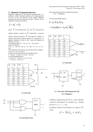
1) The document discusses various methods for implementing Boolean functions using multiplexers, including Shannon expansion. It provides examples of using 2x1, 4x1, and 8x1 multiplexers to realize functions. 2) Shannon expansion allows decomposing a Boolean function into sums of two subfunctions. This allows implementing functions using smaller multiplexers. 3) Larger multiplexers can be built by combining smaller multiplexers. Look-up tables (LUTs) can also implement small logic functions and be combined to realize more complex functions using Shannon expansion.