Downloaded 33 times


![Modeling and Simulation
Wind Turbine Dynamic Model [1]
The tip-speed ratio, λ(t), is defined as
(3)
The rotor power, Paero (t), can also be written as
(4)
Aerodynamic torque applied to the rotor by the wind. An expression for τ𝑎𝑒𝑟𝑜 can
be derived from (2)-(4) as
(5)
λ = 𝜔
𝑅
𝑉
Paero = τ𝑎𝑒𝑟𝑜 𝜔
τ𝑎𝑒𝑟𝑜 = ½𝜌𝐴𝑅
𝐶𝑝
λ
𝑉2
24](https://image.slidesharecdn.com/implementationandassemplingofasmallwindturbine-160807225821/85/Implementation-and-assemplingof-a-small-wind-turbine-24-320.jpg)
![Modeling and Simulation
Mechanical Subsystem Dynamics
𝐽𝜔∙ + f = 𝜏𝑒𝑚
25
The mechanical subsystem that describes the rotor dynamics of the
variable speed wind turbine can be of the following form:
(6)
where J ∈ R+ is the rotor moment of inertia, ω˙(t) ∈ R is the rotor
acceleration, f (ω,va) ∈ R represents the system unknown nonlinearities
and is defined as f =−τaero, and τem ∈ R+ is the electromagnetic
torque and is considered as the torque control input for the generator.
[1] J Control Theory Appl 2012](https://image.slidesharecdn.com/implementationandassemplingofasmallwindturbine-160807225821/85/Implementation-and-assemplingof-a-small-wind-turbine-25-320.jpg)
![Modeling and Simulation
Induction Yaw Motor Modeling [2]
𝜏𝑖𝑛𝑑 = 𝐾 𝐵𝑠 ₓ 𝐵𝑅 (1)
𝜏𝑚𝑎𝑥 =
3𝑉𝑡ℎ2
2𝜔𝑠 (𝑅𝑡ℎ + 𝑅𝑡ℎ2+ 𝑋𝑡ℎ+𝑋2 2
(2)
𝑃𝑖𝑛 = 3 𝑉𝑇 𝐼𝐿 𝑐𝑜𝑠 𝜃 (3)
𝑃𝑜𝑢𝑡 = 𝜏𝑙𝑜𝑎𝑑 ₓ 𝜔𝑚 (4)
26
[2] stephen j. chapman electric machinery fundamentals](https://image.slidesharecdn.com/implementationandassemplingofasmallwindturbine-160807225821/85/Implementation-and-assemplingof-a-small-wind-turbine-26-320.jpg)
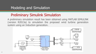


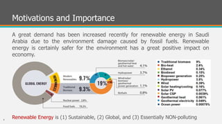
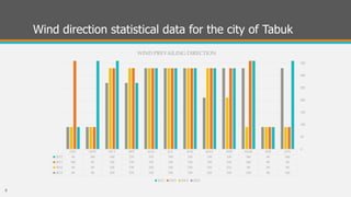
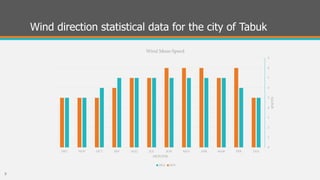
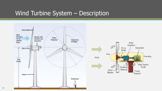
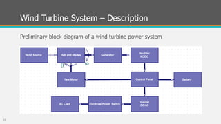
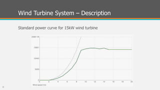
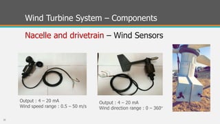
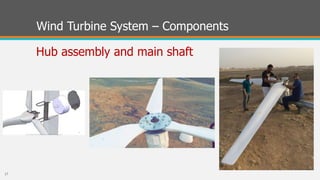
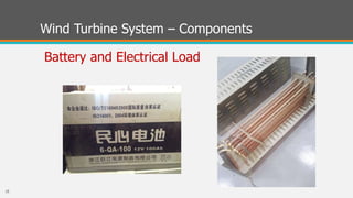
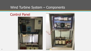
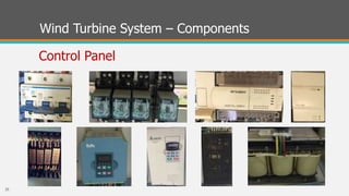
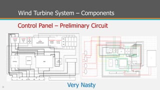
This document summarizes a student project to assemble and implement a small wind turbine. It includes the following: 1) The project aims to assemble unlabeled wind turbine components in the lab to understand how wind energy is converted to electricity. 2) Challenges include a lack of documentation for the components and difficulties integrating the mechanical parts. 3) A preliminary simulation of the wind turbine system was developed in Simulink to model the rotor dynamics, induction generator, and wind energy conversion process. 4) While the project faced challenges integrating the unlabeled components, it provides an educational opportunity to learn about renewable energy systems.