Download to read offline

![Hayder Al-Khafaji
http://www.iaeme.com/IJCIET/index.asp 113 editor@iaeme.com
High strength concrete was used to repair of all types of structural concrete elements in
buildings, water retaining structures, industrial plants, bridges, etc. where provide high
strength and extremely low shrinkage properties are required.
Externally bonded, CFRP sheets are currently being studied and applied around the world
for the repair and strengthening of structural concrete members [1]. CFRP materials are of
great interest to the civil engineering community because of their superior properties such as
high stiffness and strength has well as ease of installation when compared to other repair
materials.
David, E.,Djelal, C. and Buyle-Bodin , F. [2],using externally CFRP strips to bounded
beams and their results show that CFRP is very effective for flexure strengthening.
S. Panchacharam and A. Belarbi [3], makings experimental study to investigate the
torsional behavior of RC beams strengthened with externally bonded GFRP sheets. The
variables considered in this study are fiber orientation (parallel and perpendicular to the
longitudinal axis of the beam). The torsional reinforced concrete beams strengthened with
GFRP sheets exhibited significant increase in their cracking and ultimate strength as well as
ultimate twist deformations.
R.Dhanaraj and E.Chandrasekaran [4], investigated the numerical study on un retrofitted
and retrofitted reinforced concrete beams subjected to combined bending and torsion by
ANSYS. Then the study has been extended for the same reinforced concrete beams retrofitted
with carbon fiber reinforced plastic composites with ±45° and 0/90° fiber orientations. The
present study reveals that the CFRP composites with ±45° fiber orientations are more
effective in retrofitting the RC beams subjected to combined bending and torsion for higher
torque to moment ratios.
Bonfiglioli et al (2004)[5], carried out an experimental and theoretical study to evaluate
the capability of dynamic testing to give useful information about the stiffness recovery due to
external CFRP strengthening of RC beams which were previously damaged. Specimens were
damaged under cycle loading until cracks appeared. Then CFRP used for repairing cracking
specimens. The theoretical results are in good agreement with the experimental ones. The
research suggests that dynamic testing can be used to obtain useful information about the
effectiveness of the strengthening system.
Ali (2007)[6], casted twenty eight reinforced concrete beams to investigate the behavior of
using CFRP to repaired and strengthened beams failed in flexure and shear zone. All beams
had been tested as a simply supported beam under two point of loading. From the results can
see the use of CFRP as external strengthening has significant effect on ultimate load, crack
pattern and deflection. The repaired beams reach (95% to 97%) of ultimate load in
comparison with those strengthened in the same way by CFRP.
AL-Saidy et al. (2007)[7], studied behavior of corroded damaged reinforced concrete
beams repair/strengthening with CFRP sheets. Ten beams were casted and tested up to failure.
Damaged beams were repaired by bonding CFRP sheets to the tension side to restore the
strength loss due to corrosion. From the results can see The use of CFRP sheets for
strengthening corroded reinforced concrete beams increasing the ultimate strength of repaired
specimens. Deflection was increased for all repaired beams as compared with control beam.
Abed Al-Amery (2009)[8], repaired ten damaged reinforced concrete beams at flexural
region. Steel and CFRP palates used for repairing work to investigate the effect of repairing
materials in restoring the original stiffness and capacity for damage beams. Beams tested as
simply supported beam under two point loading. It was observed that ultimate can be
increased up to (121.4%) in the case of using steel plates. While deflection was decreased to](https://image.slidesharecdn.com/ijciet1001012-190222051546/85/Ijciet-10-01_012-2-320.jpg)
![Torsional Behavior of Repaired Reinforced Concrete Beams with Multi-Boundary Conditions
http://www.iaeme.com/IJCIET/index.asp 114 editor@iaeme.com
(15.4%) times .In case of using CFRP plates, the ultimate can be increased up to (64.3%).
While deflection was decreased to (28.6%) times of the original beams.
Nada S. Assi [9], using finite element method to adopted by ANSYS program for four
beams strengthened in flexure with different length of CFRP sheet to confirm the theoretical
calculations as well as to provide a valuable supplement to the laboratory investigation of
behavior of beams. Good agreement with the experimental test is obtain and this study shows
that the optimum length of CFRP plate equal to 83% of the full span length [10,11].
T.Abdo and R. Mabrouk[12],studied the behavior of simply supported RC beams with
openings subjected to pure torsion then verified using FEM analysis program ANSYS16.
Good agreement between the experimental and numerical results is found. The torque-rotation
relationship for all the beams under study was linear up to the cracking torque and after that it
became nonlinear.
2. MATERIALS CHARACTERISTICS:
The materials of the structural elements that analysis in this study include concrete, steel
reinforcing bars, Cempatch S and CFRP. The finite element models adopted have a number of
parameters, which are summarized in Table (1).
Table (1) Parameters for elements used in F.E. Model for beam
Representation Element Type Characteristics
Concrete Solid65
compressive strength (fc')=30 MPa
Poisson's ratio=0.2
modulus of elasticity=25742 MPa
ultimate strain=0.003
Steel Reinforcement Link180
Ø16, Ø12, Ø10
Yield strength=410 MPa
CFRP Shell41
Cempatch S Solid65
compressive strength (fc')=85 MPa
Poisson's ratio=0.17
modulus of elasticity=43332 MPa
ultimate strain=0.0045
Steel plate Solid185
modulus of elasticity=200000 MPa
Poisson's ratio=0.3
3. NUMERICAL ANALYSIS
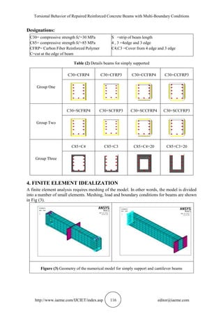
The finite elements representation using ANSYS16.1 program has been applied in this study
to know the validate of the numerical representation of the reinforced concrete beams
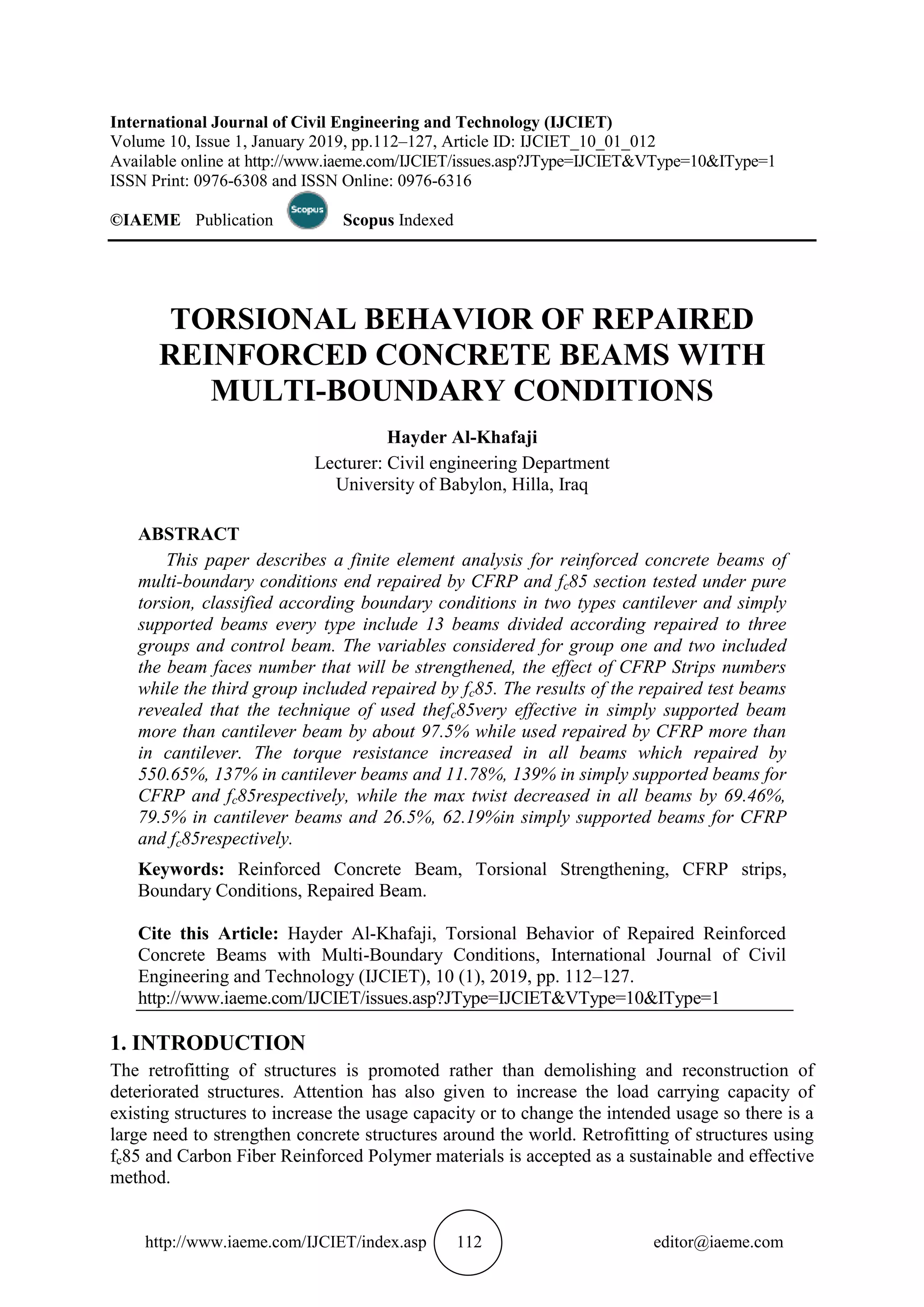
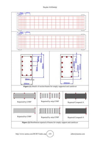
strengthening with Cempatch S and CFRP subjected to pure torsion. Twenty six reinforced
concrete beams of 500*250 mm cross-section and 2550 mm length were tested in this study
Fig (1). Schematic representations of the repairing and strengthening schemes are shown in
Fig (2) and Table (2) shows the cases of beams.](https://image.slidesharecdn.com/ijciet1001012-190222051546/85/Ijciet-10-01_012-3-320.jpg)
![Hayder Al-Khafaji
http://www.iaeme.com/IJCIET/index.asp 117 editor@iaeme.com
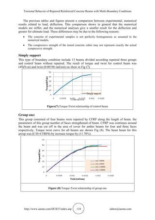
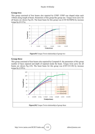
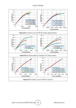
5. RESULTS AND DISCUSSIONS
In this section, the results obtained from ANSYS 16.1 are displayed for 26 beams divided
according boundary condition in two types cantilever and simply support each type include 13
beams. Because there is no experimental program for this research and compare it with the
results of the ANSYS. Therefore, the effectiveness of the program was verified through
another research that contains experimental results [3]. The general behavior of beams of
finite element represented in the torque-twist plots showed good convention with the data of
test from the experimentally tested. The torque-twist curves were show in Fig (4)to(6) and
Table(3).
Designations
A90W4:90 degree complete wrap
A0L4:0 degree, 4 sides
Table (3) Comparison between experimental and numerical ultimate torque and twist
Beam
Ultimate Torque (kN-m) Ultimate Twist (rad/mm)
Experimental Numerical
Percentage
Difference %
Experimental Numerical
Percentage
Difference %
reference 18 19.5 -8.3 110 104 5.45
A90W4 45 48 -6.67 70 63 10
A0L4 29 31.25 -7.76 168 152 9.53
Figure (4) Torque-Twist relationship of reference beam
Figure (5) Torque-Twist relationship of
beam(A90W4)
Figure (6) Torque-Twist relationship of
beam(A0L4)](https://image.slidesharecdn.com/ijciet1001012-190222051546/85/Ijciet-10-01_012-6-320.jpg)
![Hayder Al-Khafaji
http://www.iaeme.com/IJCIET/index.asp 127 editor@iaeme.com
REFERENCES
[1] Meier, U. : "Post-strengthening by continuous fiber sheets in Europe. Proceedings of
Third International Symposium, Non-Metallic (FRP) Reinforcement for Concrete
Structures", Vol. 1, Japan Concrete Institute, Tokyo, pp. 41–56, 1997.
[2] David ,E.,Djelal, C. and Buyle-Bodin , F.: " Repair and Strengthening of Reinforced
Concrete Beams using Composite Materials", second Int. PhD. Symposium in Civil
Engineering, 1998 Budapest, WWW.vbt.bme.hu.
[3] S. Panchacharam and A. Belarbi: "Torsional Behavior of Reinforced Concrete Beams
Strengthened with FRP Composites", First FIB Congress, Osaka, Japan, October 13-
19,2002.
[4] R.Santhakumar R.Dhanaraj and E.Chandrasekaran "Behaviour of retrofitted reinforced
concrete beams under combined bending and torsion".
[5] Bonfiglioli, B., Migo, S., M., Pascale, G., "Dynamic Testing of Reinforced Concrete
Beams Damaged and Repaired with Fiber Reinforced Polymer Sheets", Journal of
materials in civil engineering, ASCE, September 2004.
[6] Ali, D., D., "Experimental and Theoretical Investigation of the Behavior of Reinforced
Concrete Beams Strengthened by Fiber Reinforced Polymer" Ph.D. Thesis, University of
Baghdad, January 2007.
[7] Al-Saidy, A., H., Al-Harthy, A., S., Abdul-Halim, M., Al-Jabri, K., S., Al-shidi, N.,
M.,"Repair Strengthening of Corrosion Damaged Concrete Beams with Fiber Reinforced
Polymers Sheets", University of Patras, Patras, Greece, July 2007.
[8] Abed Al-Amery, S., J., "Behavior of RC Beams Repaired with Steel and CFRP Plates",
M.Sc. Thesis, AI -Mustansiriya University, Iraq, January- 2009.
[9] Nada S. Assi: " The Effect of Carbon Fiber Reinforced Polymer Length on the
Strengthened of Concentrically Loaded Reinforced Concrete Beams : Finite Element
Analysis", Vol. 32, Part (A), No.7, Eng. & Tech. Journal, pp. 1671-1683, 2014.
[10] Kadhim Naief Kadhim and Ghufran A. (The Geotechnical Maps For Gypsum By Using
Gis For Najaf City (Najaf - Iraq) (IJCIET), Volume 7, Issue 44, July-August 2016.
[11] Hassan and Kadhim Naief Kadhim (Development an Equation for Flow over Weirs Using
MNLR and CFD Simulation Approaches). (IJCIET), Volume 9, Issue 3, (Feb 2018)
[12] T. Abdo and R. Mabrouk" Effect of web openings on the structural behavior of RC beams
subjected to pure torsion"](https://image.slidesharecdn.com/ijciet1001012-190222051546/85/Ijciet-10-01_012-16-320.jpg)

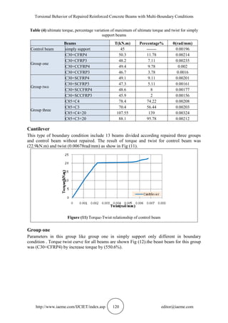
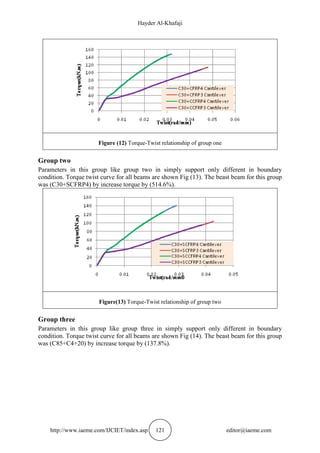
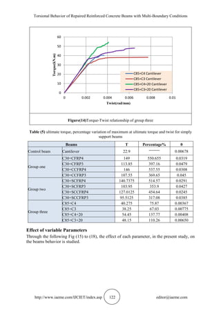
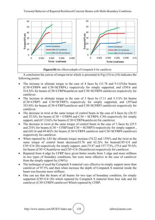
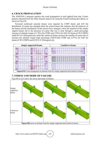
This document presents a study on the torsional behavior of repaired reinforced concrete beams with multi-boundary conditions, utilizing finite element analysis. The research evaluates the effectiveness of two repair techniques—carbon fiber reinforced polymer (CFRP) and high strength concrete (fc85)—in enhancing the torque resistance and reducing twist deformation of beams. Results indicate a significant improvement in performance, particularly with the use of fc85 in simply supported beams, showing remarkable increases in torque capacity and reductions in twist.


