This research focuses on retrofitting reinforced concrete (RC) beams using glass fiber reinforced polymer (GFRP) and carbon fiber reinforced polymer (CFRP) sheets to enhance their load-carrying capacity and reduce deflections and crack widths. The study analyzed the flexural behavior of various grades of RC beams retrofitted with different layers of GFRP sheets through experimental tests and finite element modeling using ANSYS software. Results indicated that the use of CFRP and GFRP considerably improved the structural performance of the retrofitted beams compared to control beams.
![International Journal of Trend in Scientific Research and Development @ www.ijtsrd.com eISSN: 2456-6470
@ IJTSRD | Unique Paper ID – IJTSRD52006 | Volume – 6 | Issue – 6 | September-October 2022 Page 1011
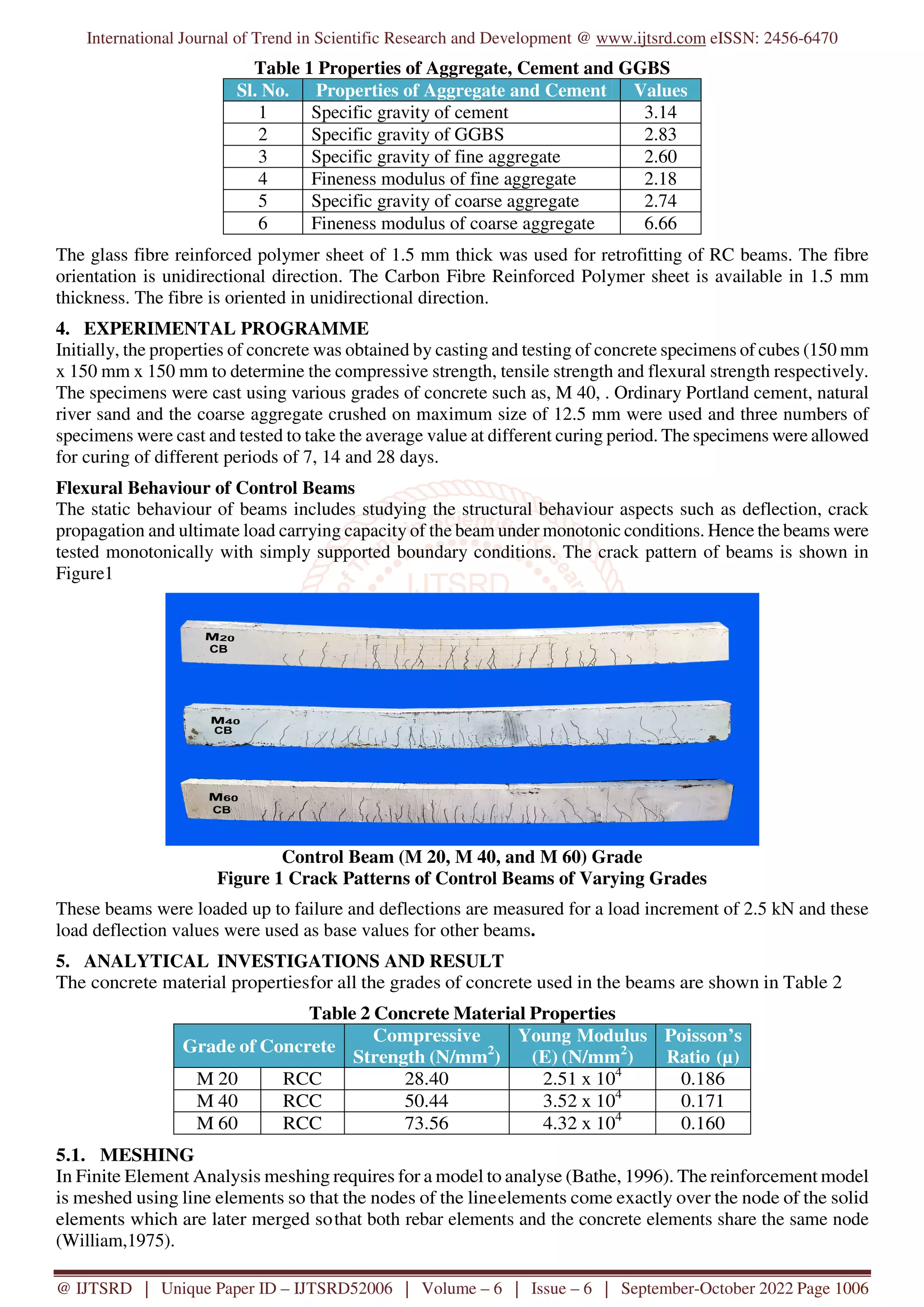
The cracks distribution indicates that the size and
density of crack are lower in the GFRP and CFRP
strengthened beams than in the control beams.
7. REFERENCES
[1] Sharba, Amjad Ali K., Hussain Dhafir
Hussain, and Mohammed Abdulhussain.
"Retrofitting of RC beams using FRP
techniques: a review.” In IOP Conference
Series: Materials Science and Engineering,
vol. 1090, no. 1, p. 012054. IOP Publishing,
2021.
[2] Askar, Mand Kamal, Ali Falyeh Hassan, and
Yaman SS Al-Kamaki. "Flexural and Shear
Strengthening of Reinforced Concrete Beams
Using FRP Composites: A State of The Art.”
Case Studies in Construction Materials
(2022): e01189.
[3] Abbasi, Amirali, Omar Chaallal, and Georges
El-Saikaly. "Shear strengthening of RC
beams with FRP composites: Database of FE
simulations and analysis of studied
parameters.” Modelling and Simulation in
Engineering 2022 (2022).
[4] Panahi, Minoo, Seyed Alireza Zareei, and
Ardavan Izadi. "Flexural strengthening of
reinforced concrete beams through externally
bonded FRP sheets and near surface mounted
FRP bars.” Case Studies in Construction
Materials 15 (2021): e00601.
[5] Rabia, Benferhat, Tahar Hassaine Daouadji,
and Rabahi Abderezak. "Effect of air bubbles
in concrete on the mechanical behavior of
RC beams strengthened in flexion by
externally bonded FRP plates under
uniformly distributed loading.” 1 3, no. 1
(2021): 41.
[6] ACI Committee 440 Report, “Guide for the
design and construction of externally bonded
FRP systems strengthening concrete
structures”, (Revised 24 May 2000).
American Concrete Institute, Farming Hills,
Michigan, 2000, 1-89.
[7] ACI Committee 440. 2 R-02 (2002), Guide
for the design and construction of externally
bonded FRP systems for strengthening
concrete structures.
[8] Aiello. M. A., and Ombres. L., (2004),
Cracking and deformability analysis of
reinforced concrete beams strengthened with
externally bonded carbon fiber reinforced
polymer sheets, Journal of Material in Civil
Engineering, 16(5), 392-399.
[9] Alagusundaramoorthy. P., Harik. I. E., M.
ASCE., and Choo. C. C., (2003), Flexural
behavior of RC beams strengthened with
carbon fiber reinforced polymer sheets of
fabric, Journal of Composites for
Construction, 7(4), 292-301.
[10] Ali, Abdel-Zaher and Ambalavanan, R.,
(1998), Development and behavior of repair
mortars for RC components, The Indian
Concrete Journal, 669-675.
[11] ANSYS, (2003), The general purpose finite
element software, version 8. 0, Swanson
Analysis systems, Inc., International
Houston, TX, USA.
[12] Anwar, A. W., Nimityongskul, P., Pama, R.
P., and Austriaco, L., (1991), Method of
rehabilitation of structural beams elements
using ferrocement, Journal of Ferrocement,
21(3), 229-234.
[13] Daniel, Isaac M., Ori Ishai, Issac M. Daniel,
and Ishai Daniel. Engineering mechanics of
composite materials. Vol. 1994. New York:
Oxford university press, 2006.
[14] Åström, B. Tomas. Manufacturing of polymer
composites. Routledge, 2018.](https://image.slidesharecdn.com/119reinforcementofreinforcedconcretebeamsusingcfrpandgfrp-221108053302-a7f55538/75/Reinforcement-of-Reinforced-Concrete-Beams-using-CFRP-and-GFRP-8-2048.jpg)


![11.[1 10]shear strength study of rc beams retrofitted using vinyl ester bonded](https://cdn.slidesharecdn.com/ss_thumbnails/11-1-10shearstrengthstudyofrcbeamsretrofittedusingvinylesterbonded-120512235418-phpapp02-thumbnail.jpg?width=640&height=640&fit=bounds)


