This document summarizes a research paper that proposes a two-level control system to improve maximum power point tracking (MPPT) in photovoltaic systems. The first level uses ripple correlation control to calculate the duty cycle for maximum power output. The second level uses model reference adaptive control to eliminate transient oscillations in output voltage caused by duty cycle changes. Simulation results showed the system converges rapidly to the maximum power point with minimal output voltage oscillation under changing environmental conditions.
![International Journal of Electrical and Computing Engineering
Vol. 1, Issue. 3, April – 2015 ISSN (Online): 2349-8218
1
MODIFIED MPPT SCHEME FOR IMPROVING SOLAR CELL
POWER OUTPUT FOR MULTI-INPUT INVERTER
HARIHARAN.R1
, HARIHARAN.Ve2
, ASHOK.B3
, SURENDHARAN.P4
1,2,3,4
Electrical and Electronics Engineering, Vel Tech, Chennai, INDIA
Abstract- The performance of a photovoltaic (PV)
module is mostly affected by array configuration,
irradiance, and module temperature. It is important to
understand the relationship between these effects and the
output power of the PV array. This paper proposes an
adaptive control architecture for maximum power point
tracking (MPPT) in photovoltaic systems. MPPT
technologies have been used in photovoltaic systems to
deliver the maximum available power to the load under
changes of the solar insolation and ambient temperature.
To improve the performance of MPPT, this paper develops
a two-level adaptive control architecture that can reduce
complexity in system control and effectively handle the
uncertainties and perturbations in the photovoltaic
systems and the environment. The first level of control is
ripple correlation control (RCC), and the second level is
model reference adaptive control (MRAC). By decoupling
these two control algorithms, the system achieves MPPT
with overall system stability. This paper focuses mostly on
the design of the MRAC algorithm, which compensates
the under damped characteristics of the power conversion
system. The original transfer function of the power
conversion system has time-varying parameters, and its
step response contains oscillatory transients that vanish
slowly. An adaption law of the controller is derived for the
MRAC system to eliminate the under damped modes in
power conversion. It is shown that the proposed control
algorithm enables the system to converge to the maximum
power point in milliseconds.
Index Terms—Maximum power point tracking
(MPPT), model reference adaptive control (MRAC),
photovoltaic system, ripple correlation control (RCC).
I. INTRODUCTION
PHOTOVOLTAIC systems are a critical component
in addressing the national mandates of achieving
energy independence and reducing the potentially
harmful environmental effects caused by increased
carbon emissions. Due to variations in solar
insolation and environmental temperature,
photovoltaic systems do not continually deliver their
theoretical optimal power unless a maximum power
point tracking (MPPT) algorithm is used. MPPT
algorithms are designed in order for the photovoltaic
system to adapt to environmental changes so that
optimal power is delivered. Typically, MPPT
algorithms are integrated into power electronic
converter systems, where the
Fig. 1.Power–voltage characteristics of photovoltaic
systems.
duty cycle of the converter is controlled to deliver
maximum available power to the load [1], [2].
Several MPPT algorithms have been reported in the
literature. The most common of these algorithms is
the perturb and observe (P&O) method [3]–[5]. This
control strategy requires external circuitry to
repeatedly perturb the array voltage and subsequently
measure the resulting change in the output power.
While P&O is inexpensive and relatively simple, the
algorithm is inefficient in the steady state because it
forces the system to oscillate around the maximum
power point (MPP) instead of continually tracking it.
Furthermore, the P&O algorithm fails under rapidly
changing environmental conditions, because it cannot
discern the difference between changes in power due
to environmental effects versus changes in power due
to the inherent perturbation of the algorithm [6]. The
incremental conductance (INC) method uses the fact
that the derivative of the array power with respect to
the array voltage is ideally zero at the
MPPT(seeFig.1), positive to the left of the MPP, and
negative to the right of the MPP. The INC method
has been shown to perform well under rapidly
changing environmental conditions, but at the](https://image.slidesharecdn.com/iisrthariharanravichandran31-36-150705075054-lva1-app6891/75/Iisrt-hariharan-ravichandran-31-36-1-2048.jpg)
![International Journal of Electrical and Computing Engineering
Vol. 1, Issue. 3, April – 2015 ISSN (Online): 2349-8218
32
expense of increased response times due to complex
hardware and software requirements [7]. The
fractional open-circuit voltage (FOCV) method uses
an approximate relationship between VOC, the open-
circuit voltage of the array, and VM, the array voltage
at which maximum power is obtained, to track the
MPP [8]. Like P&O, the FOCV algorithm is
inexpensive and can be implemented in a fairly
straight-forward manner. However, the FOCV
method is not a true MPP tracker since the assumed
relationship between VOC and VM is only an
approximation. Fuzzy logic and neural network-based
algorithms have demonstrated fast convergence and
high performance under varying environmental
conditions, but the implementation of these
algorithms can be undesirably complex [9], [10]. To
this end, a general problem associated with MPPT
algorithms is the transient oscillations in the system’s
output voltage after the duty cycle is rapidly changed
in order to track the MPP [7]. Thus, the ideal MPPT
control algorithm would be simple and inexpensive,
and would demonstrate rapid convergence to the
MPP with minimal oscillation in the output voltage.
Fig. 2. Current–voltage characteristics of
photovoltaic systems under various levels of solar
insolation.
Fig. 3. MPPT controller of a photovoltaic boost
converter system
II.EXISTING SYSTEM
Petrub and Observe method works by disrupting the
system and observing the impact on power output of
PV module. If the operating voltage is disturbed in a
given direction and that the power increases (dP/dV >
0) then it is clear that the disturbance has moved the
operating point toward the MPP. The P&O algorithm
will continue to disturb the voltage in the same
direction. By cons, if the power drops (dP/dV < 0),
then the disturbance has moved the operating point
far from the MPP. The algorithm will reverse the
direction of subsequent disturbance. This algorithm is
summarized in the flowchart (Fig 4).
Fig.4.Flowchart of P&O
III.PROPOSED SYSTEM
This paper develops a two-level MPPT control
algorithm that consists of ripple correlation control
(RCC) [11]–[14] in the first level and model
reference adaptive control (MRAC) [15], [16] in the
second level. As shown in Fig. 4, in the first control
level the array voltage vPV and power pPV serve as the](https://image.slidesharecdn.com/iisrthariharanravichandran31-36-150705075054-lva1-app6891/75/Iisrt-hariharan-ravichandran-31-36-2-2048.jpg)
![International Journal of Electrical and Computing Engineering
Vol. 1, Issue. 3, April – 2015 ISSN (Online): 2349-8218
33
inputs to the RCC unit. The RCC unit then calculates
the duty cycle of the system, d(t), to deliver the
maximum available power to the load in the steady
state. In the second control level, the new duty cycle
calculated from the RCC unit is routed into an
MRAC architecture, where the dynamics of the entire
photovoltaic power conversion system, or the plant,
are improved to eliminate any potential transient
oscillations in the system’s output voltage. Transient
oscillations in the system’s output voltage can result
after the duty cycle has been updated to account for
rapidly changing environmental conditions. To
prevent the plant from displaying such oscillations, a
critically damped system is implemented as the
reference model in Fig. 5. During adaptation, the
error between the plant and reference model is
utilized to tune the parameters in the feedforward and
feedback controllers, Cf and Cb, respectively. Properly
tuning the controller parameters enables the output of
the plant to match the output of the reference model,
at which point the error converges to zero and the
maximum power is obtained. Both the theoretical and
simulation results demonstrate convergence to the
optimal power point with elimination of
underdamped responses that are often observed in
photovoltaic power converter systems.
The proposed two-level controller structure can
reduce the complexity in system control, with RCC
mainly handling the “slow” dynamics and MRAC
handling the “fast” dynamics. The previous literature
has proven the stability of RCC and MRAC,
respectively. Although coupling two stable
subsystems will not necessarily lead to the stability of
the overall system, our proposed two-level structure
can effectively decouple the RCC and MRAC levels
in stability analysis, because the time constants of the
two control algorithms used here are significantly
disparate. This paper focuses mostly on the MRAC
level of the proposed control architecture. In a sequel
paper (in preparation), we will provide a
comprehensive analysis validating the coupling of
MRACwithRCC.
Fig. 5 Proposed MPPT control architecture
IV.SYSTEM DESCRIPTION
Fig. 2 presents the current–voltage (I–V)
characteristics of photovoltaic systems under various
levels of solar insolation. The MPP occurs at the so-
called “knee” of the I–V curve, (VM,IM): when either
VM or IM is achieved, the maximum available power
PM is obtained.
A photovoltaic system can regulate the voltage or
current of the solar panel using a dc–dc converter
interfaced with an MPPT controller to deliver the
maximum allowable power [17], [18]. Fig. 4 shows
the integration of such a system where a boost
converter is utilized to deliver optimal power to the
load. Depending on the application, other power
converter topologies may be used in place of the
boost converter. In the boost converter system shown
in Fig. 4, the MPPT controller senses the voltage and
current of the solar panel and yields the duty cycle d
to the switching transistor S. The duty cycle of the
transistor is related to the array voltage through
vPV = iPVRO(1 − d)2
where vPV and iPV are the array voltage and current,
respectively, and RO is the load resistance. Both the
array voltage and current consist of dc (average)
terms, VPV and IPV, as well as ripple terms, vˆPV
andˆiPV. The goal then is to design a controller that
continually calculates the optimal value of the duty
cycle so that VPV tracks VM (or IPV tracks IM) and thus
delivers the maximum available power.](https://image.slidesharecdn.com/iisrthariharanravichandran31-36-150705075054-lva1-app6891/75/Iisrt-hariharan-ravichandran-31-36-3-2048.jpg)
![International Journal of Electrical and Computing Engineering
Vol. 1, Issue. 3, April – 2015 ISSN (Online): 2349-8218
35
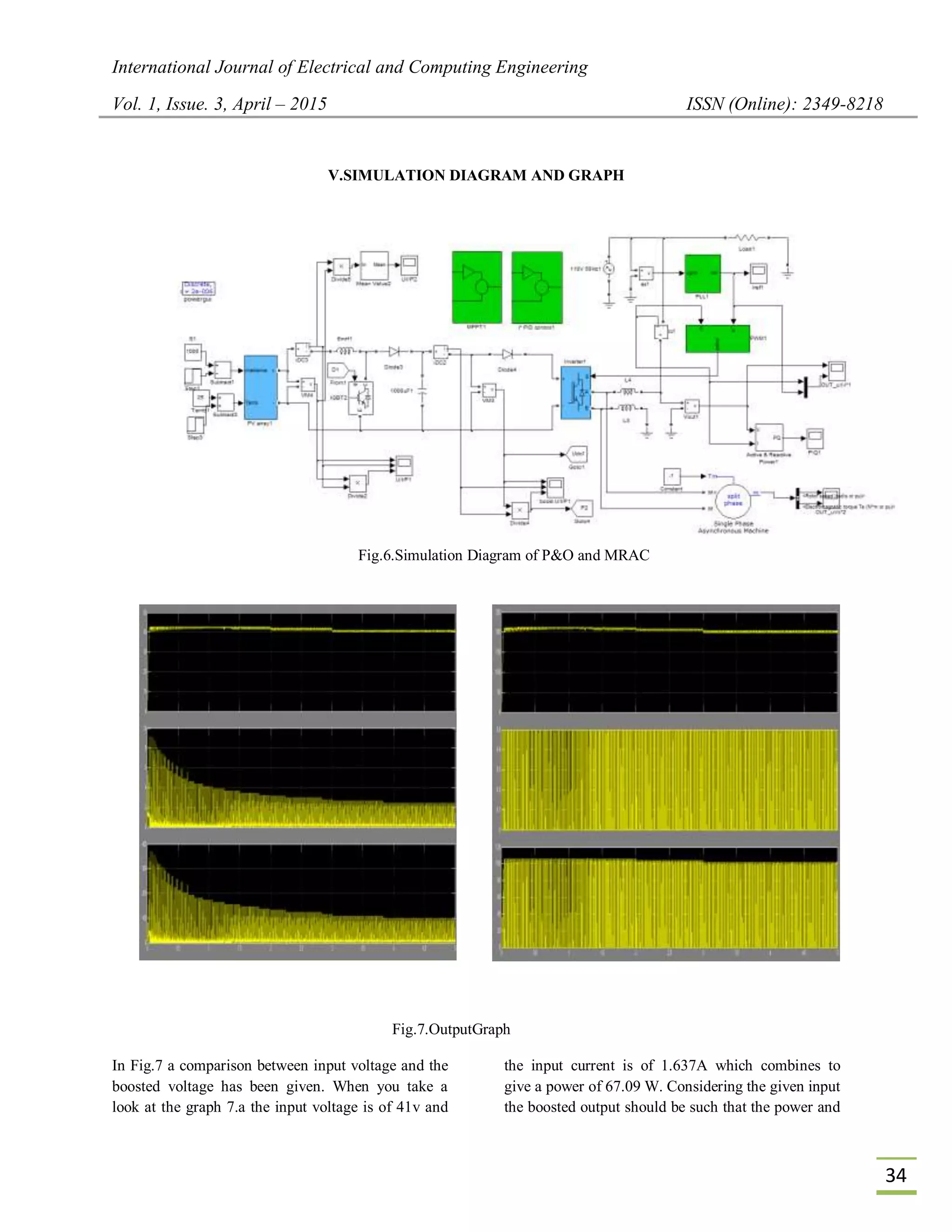
voltage increases with less settling time. The Fig.7.a
gives the voltage, current and power waveforms of
the input given to the boost converter. In the graph
you can see that the current initially rises to a peak
value as the motor starts and slowly reduces as the
load increases. Accordingly, the power also varies
with a peak power rise initially and settling as the
graph progresses.
In Fig 7.b the waveforms of boosted output is being
shown. When you take a look at the waveforms the
voltage gets boosted by three times the input value
and the boosted voltage becomes approximately
203V. This boosted voltage is obtained within a less
settling time of around 0.2 sec. The current remains
constant at 0.5 A because as the voltage gets boosted
up the current reduces. The output power also gets
boosted to 101.5W. The main reason for going to
MRAC method is to reduce the transient oscillations
associated with tracking the MPP and quickly
reaching the MPP compared to the petrub and
observe algorithm.
As one can see from the graph the boosted output
settles very quickly within a time period of 0.2 to 0.5
seconds whereas it takes around 0.7-0.9 sec in petrub
and observe algorithm from the simulation results.
VI. CONCLUSION
In order to improve the efficiency of photovoltaic
systems, MPPT algorithms are used, aiming to
deliver the maximum available power from the solar
array to the load. Critical issues to be considered in
the MPPT algorithms include system complexity,
uncertainty, and dynamical performance. This paper
developed a two-level adaptive control architecture
that can reduce complexity in system control and
effectively handle the uncertainties and perturbations
in the photovoltaic systems and the environment. The
first level of control was RCC, and the second level
was MRAC. This paper focused mostly on the design
of the MRAC algorithm, which compensated the
underdamped characteristics of the power conversion
system. In a sequel paper, we will provide a
comprehensive analysis validating the coupling of
MRAC with RCC.
VII. REFERENCES
[1] S. L.Brunton,C. W. Rowley,S. R.Kulkarni, and
C.Clarkson, “Maximum power point tracking for
photovoltaic optimization using ripple-based
extremum seeking control,” IEEE Trans. Power
Electron., vol. 25, no. 10, pp. 2531–2540, Oct.
2010.
[2] R.
A.Mastromauro,M.Liserre,T.Kerekes,andA.Dell’
Aquila,“Asinglephase voltage-controlled grid-
connected photovoltaic system with power
quality conditioner functionality,” IEEE Trans.
Ind. Electron., vol. 56, no. 11, pp. 4436–4444,
Nov. 2009.
[3] A. K. Abdelsalam, A. M. Massoud, S. Ahmed,
and P. N. Enjeti, “High-performance adaptive
perturb and observe MPPT technique for
photovoltaic-based microgrids,” IEEE Trans.
Power Electron., vol. 26, no. 4, pp. 1010–1021,
Apr. 2011.
[4] M. A. Elgendy, B. Zahawi, and D. J. Atkinson,
“Assessment of perturb and observe MPPT
algorithm implementation techniques for PV
pumping applications,” IEEE Trans. Sustainable
Energy, vol. 3, no. 1, pp. 21–33, Jan. 2012.
[5] G. Petrone, G. Spagnuolo, and M. Vitelli, “A
multivariable perturb-andobserve maximum
power point tracking technique applied to a
singlestage photovoltaic inverter,” IEEE Trans.
Ind. Electron., vol. 58, no. 1, pp. 76–84, Jan.
2011.
[6] S.JainandV.Agarwal,“Anewalgorithmforrapidtra
ckingofapproximate maximum power point in
photovoltaic systems,” IEEE Power Electron.
Lett., vol. 2, no. 1, pp. 16–19, Mar. 2004.
[7] N. Femia, G. Petrone, G. Spagnuolo, and M.
Vitelli, “Optimization of
perturbandobservemaximumpowerpointtracking
method,”IEEETrans. Power Electron., vol. 20,
no. 4, pp. 963–973, Jul. 2005.
[8] M. A. S. Masoum, H. Dehbonei, and E. F.
Fuchs, “Theoretical and experimental analyses of
photovoltaic systems with voltage and current-
based maximum power-point tracking,” IEEE
Trans. Energy Convers., vol. 17, no. 4, pp. 514–
522, Dec. 2002.
T. Esram and P. L. Chapman, “Comparison of
photovoltaic array maximum power point
tracking techniques,” IEEE Trans. Energy
Convers., vol. 22, no. 2, pp. 439–449, Jun. 2007.
[9] M. Veerachary, T. Senjyu, and K. Uezato,
“Neural-network-based maximum-power-point
tracking of coupled-inductor interleaved-](https://image.slidesharecdn.com/iisrthariharanravichandran31-36-150705075054-lva1-app6891/75/Iisrt-hariharan-ravichandran-31-36-5-2048.jpg)
![International Journal of Electrical and Computing Engineering
Vol. 1, Issue. 3, April – 2015 ISSN (Online): 2349-8218
36
boostconverter-supplied PV system using fuzzy
controller,” IEEE Trans. Ind. Electron., vol. 50,
no. 4, pp. 749–758, Aug. 2003.
[10] P. T. Krein, “Ripple correlation control, with
some applications,” in Proc. IEEE Int. Symp.
Circuits Syst., 1999, vol. 5, pp. 283–286.
[11] D. L. Logue and P. T. Krein, “Optimization of
power electronic systems using ripple correlation
control: A dynamic programming approach,” in
Proc. IEEE 32nd Annu. Power Electron. Special.
Conf., 2001, vol. 2, pp. 459–464.
[12] J. W. Kimball and P. T. Krein, “Discrete-time
ripple correlation control for maximum power
point tracking,” IEEE Trans. Power Electron.,
vol. 23, no. 5, pp. 2353–2362, Sep. 2008.](https://image.slidesharecdn.com/iisrthariharanravichandran31-36-150705075054-lva1-app6891/75/Iisrt-hariharan-ravichandran-31-36-6-2048.jpg)