Download to read offline

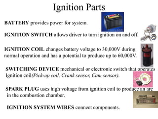
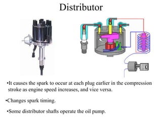
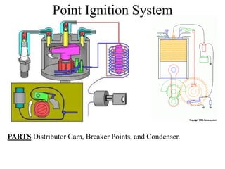
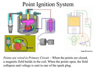
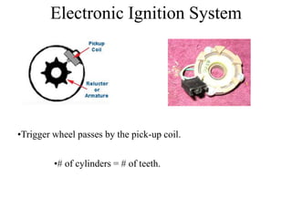
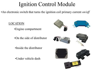
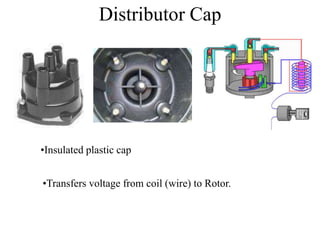
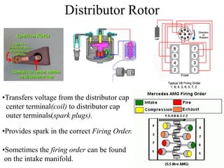
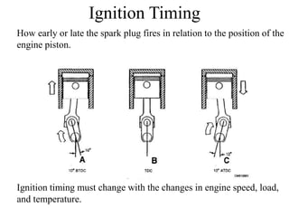
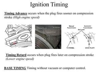
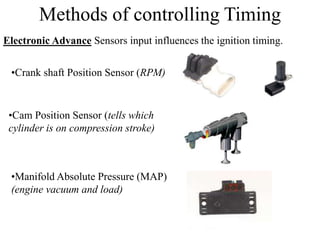
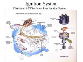

The ignition system provides spark to ignite the air-fuel mixture in spark-ignition engines. It uses an ignition coil to generate high voltage sparks for the spark plugs, which are timed to fire as the pistons near top dead center on the compression stroke. Sensors detect engine speed and load to vary ignition timing for optimal performance and efficiency. The distributor routes high voltage ignition to each cylinder in the correct firing order.


